EPKWMT05TXAcumen, Inc. Wall Mount Programmable Thermostat W
Acumen Technologies Ltd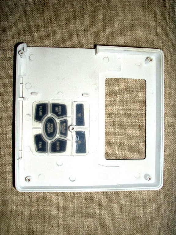
Click to zoom
Application Details
- Equipment Class
- DXX - Part 15 Low Power Communication Device Transmitter
- Date of Grant
- Aug 13, 2003
- Application Purpose
- Original Equipment
- Date of Application
- Aug 13, 2003
- Equipment Note
- Acumen, Inc. Wall Mount Programmable Thermostat W
- Frequency Range
- 350.10000000 - 350.10000000
- Company
- Acumen Technologies Ltd
- Country
- China
Documents & Files
Document Text
Text extracted from the exhibit documents filed with the FCC. Open a document above to read the original.
Block Diagram
Intertek Model #: WMT FCC ID: EPKWMT05TX A2LA Code:121624 1 of 1 Block Diagram
Internal Photos
Intertek Model #: WMT FCC ID: EPKWMT05TX A2LA Code:121624 1 of 5 Equipment Photographs Photograph 1: Overview – Inside Chassis Photograph 2: Inside Cover Photograph 3: PCB – Component Side Photograph 4: PCB – Display Side Intertek Model #: WMT FCC ID: EPKWMT05TX A2LA Code:121624 2 of 5 Photograph: 1 Overview – Inside Chassis WMT Intertek Model #: WMT FCC ID: EPKWMT05TX A2LA Code:121624 3 of 5 Photograph: 2 Inside Cover WMT Intertek Model #: WMT FCC ID: EPKWMT05TX A2LA Code:121624 4 of 5 Photograph: 3 PCB – Component Side WMT Intertek Model #: WMT FCC ID: EPKWMT05TX A2LA Code:121624 5 of 5 Photograph: 4 PCB – Display Side WMT
Test Report
Intertek EMC Report for Acumen, Inc. on the WMT FCC Part 15.231 File: 3038984-37-1-1 Page 2 of 18 TABLE OF CONTENTS 1 Summary of Tests.................................................................................................................3 2 General Description..............................................................................................................4 2.1 Product Description....................................................................................................4 2.2 Related Submittal(s) Grants..........................................................................................4 2.3 Test Methodology.......................................................................................................4 2.4 Test Facility...............................................................................................................5 3 System Test Configuration...................................................................................................6 3.1 Support Equipment.....................................................................................................6 3.2 Cabling......................................................................................................................6 3.3 Block Diagram of Test Setup.......................................................................................6 3.4 Justification................................................................................................................7 3.5 Software Exercise Program.........................................................................................7 3.6 Mode of Operation During Test....................................................................................7 3.7 Modifications Required for Compliance.........................................................................7 3.8 Additions, deviations and exclusions from standards.......................................................7 4 Measurement Results...........................................................................................................8 4.1 Radiated Emission.......................................................................................................8 4.1.1 Procedure.......................................................................................................8 4.1.2 Field Strength Calculation.................................................................................8 4.1.3 Test Result.....................................................................................................9 4.2 AC Line Conducted Emission.......................................................................................10 4.2.1 Measurement Procedure...................................................................................10 4.2.2 Test Result.....................................................................................................11 4.3 Occupied Bandwidth Plot.............................................................................................12 4.4 Transmitter Duty Cycle Calculation and Measurements...................................................13 5 Antenna Requirement..........................................................................................................16 6 List of test equipment...........................................................................................................17 7 Document History.................................................................................................................18 Intertek EMC Report for Acumen, Inc. on the WMT FCC Part 15.231 File: 3038984-37-1-1 Page 4 of 18 2 General Description 2.1 Product Description The test results in this report pertain only to the item(s) tested. The following description of the Wall Mount Programmable Thermostat was supplied by Acumen, Inc.: Overview of the EUT Applicant Acumen, Inc. 101A Executive Drive, Suite 200 Sterling, VA 20166 Trade Name & Model No. Wall Mount Programmable Thermostat / WMT FCC Identifier EPKWMT05TX Use of product Programmable Thermostat Transmitter activation [ x] Manual and automatically deactivate within 5 seconds of being released [ ] Periodic transmissions Frequency Range (MHz) 350.1 Antenna Requirement The EUT uses a permanently connected antenna. Manufacturer name & address Acumen, Inc. 101A Executive Drive, Suite 200 Sterling, VA 20166 EUT type Production EUT received date: March 27, 2003 Operating condition: Good 2.2 Related Submittal(s) Grants This report is for use with an application for certification of a low power transmitter. One transmitter is included in the application. 2.3 Test Methodology Both AC mains line-conducted and radiated emissions measurements were performed according to the procedures in ANSI C63.4 (1992). Radiated tests were performed at an antenna to EUT distance of 3 meters, unless stated otherwise in the "Data Sheet" of this Application. All other measurements were made in accordance with the procedures in part 2 of CFR 47. Intertek EMC Report for Acumen, Inc. on the WMT FCC Part 15.231 File: 3038984-37-1-1 Page 5 of 18 2.4 Test Facility The Duluth 10-meter chamber site is located at 1950 Evergreen Blvd., Suite 100, Duluth, Georgia. The test site is a 10-meter semi-anechoic chamber. The site meets the characteristics of CISPR 16-1: 1993 and ANSI C63.4: 1992. For measurements, a remotely controlled flush-mount metal-top turntable is used to rotate the EUT a full 360 degrees. A remote controlled non-conductive antenna mast is used to scan the antenna height from one to four meters. The A2LA accreditation code for this site is 121624 under certificate number 1455.01. The Industry Canada file number for this site is IC 2077. Intertek EMC Report for Acumen, Inc. on the WMT FCC Part 15.231 File: 3038984-37-1-1 Page 6 of 18 3 System Test Configuration 3.1 Support Equipment No support equipment was needed for this evaluation. 3.2 Cabling No cables were needed fo…
Text truncated - open the document above for the full version.
Test Setup Photos
Intertek Model #: WMT FCC ID: EPKWMT05TX A2LA Code:121624 1 of 3 Equipment Setup Photographs Photograph 1: Radiated Emissions – Front View Photograph 2: Radiated Emissions – Rear View Intertek Model #: WMT FCC ID: EPKWMT05TX A2LA Code:121624 2 of 3 Photograph: 1 Radiated Emissions – Front View WMT Intertek Model #: WMT FCC ID: EPKWMT05TX A2LA Code:121624 3 of 3 Photograph: 2 Radiated Emissions –Rear View WMT
Contact Information
Applicant
KY Sham
Technical Contact
IntertekJeremy Pickens
[email protected]678 775 2400
1950 Evergreen Blvd. · Duluth, Georgia · United States
Non-Technical Contact
IntertekJeremy Pickens
[email protected]678 775 2400
Test Firm
Intertek Testing ServicesDavid Schramm
Technical Specifications
| # | Rule Parts | Frequency Range | Power Output |
|---|---|---|---|
| 1 | 15C | 350.1 MHz - 350.1 MHz | - |
Other Applications from Acumen Technologies Ltd
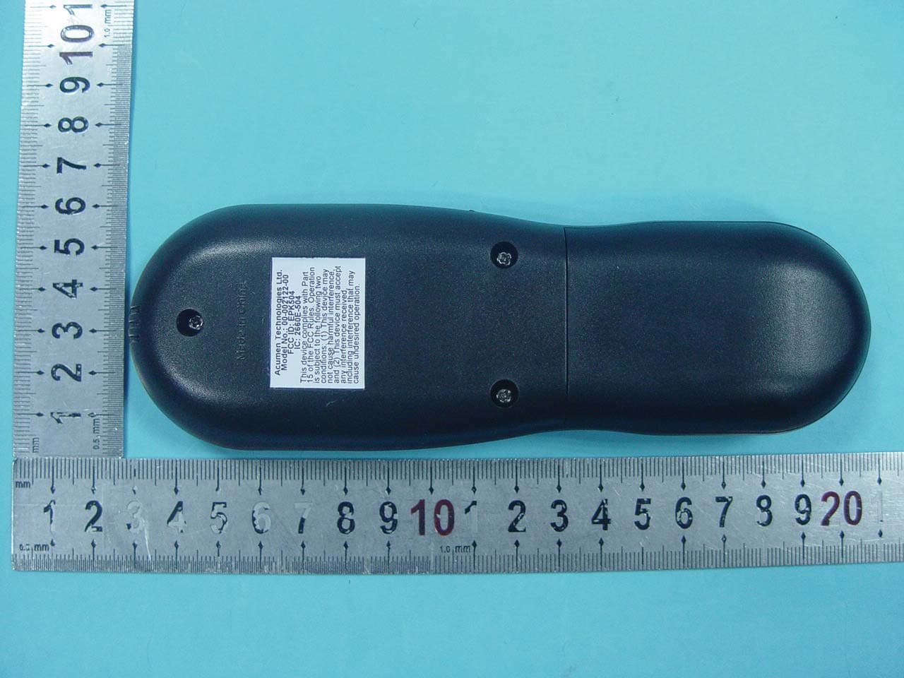
EPK504
Dec 02, 2010Acumen FDC 504 Tx Only
Equipment Class
DSC - Part 15 Security/Remote Control Transmitter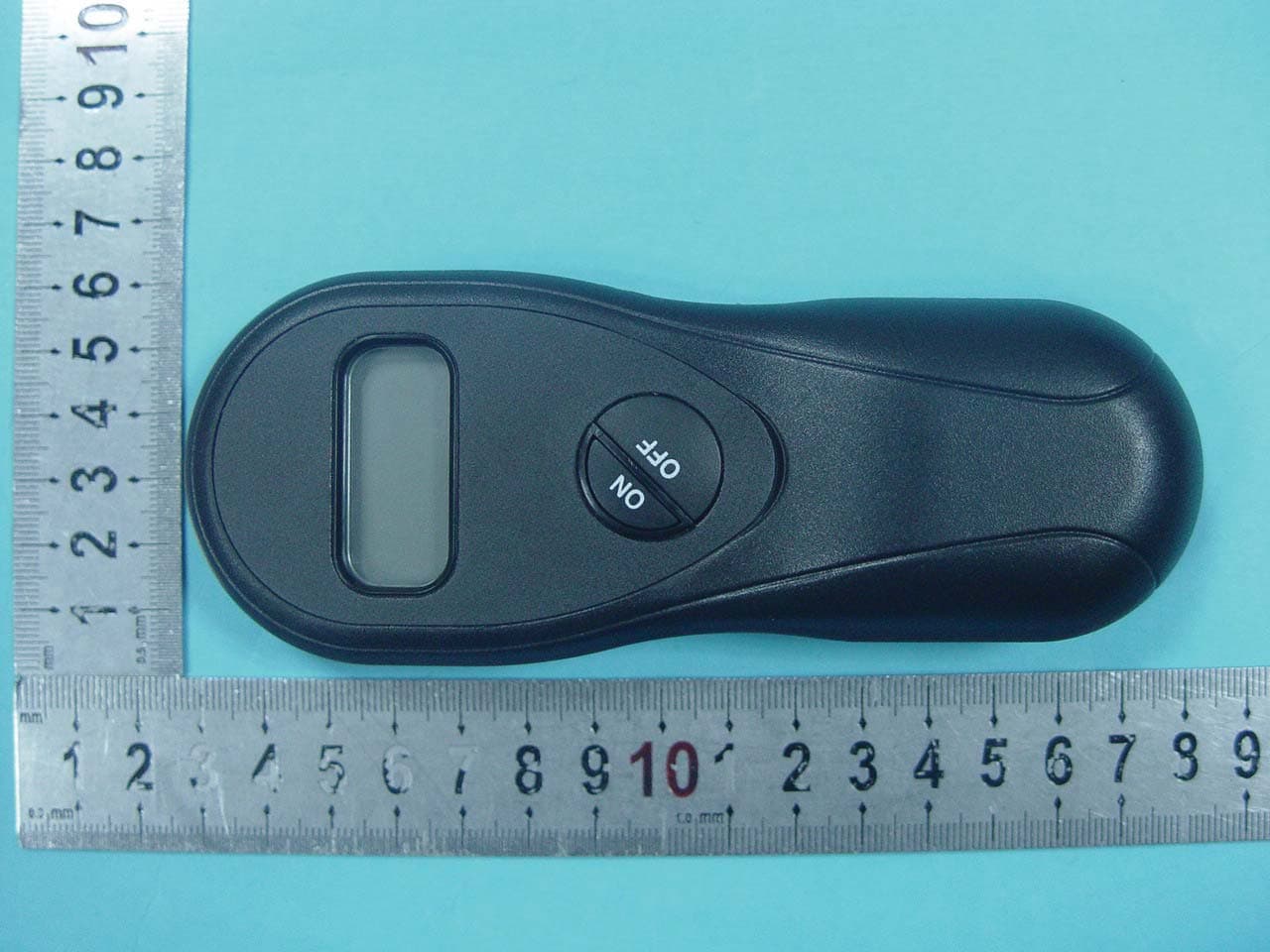
EPK502
Dec 02, 2010Acumen FDC 502 Tx Only
Equipment Class
DSC - Part 15 Security/Remote Control Transmitter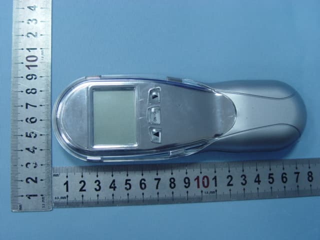
EPKEON0304
Nov 19, 2007EON 03/04
Equipment Class
DSC - Part 15 Security/Remote Control Transmitter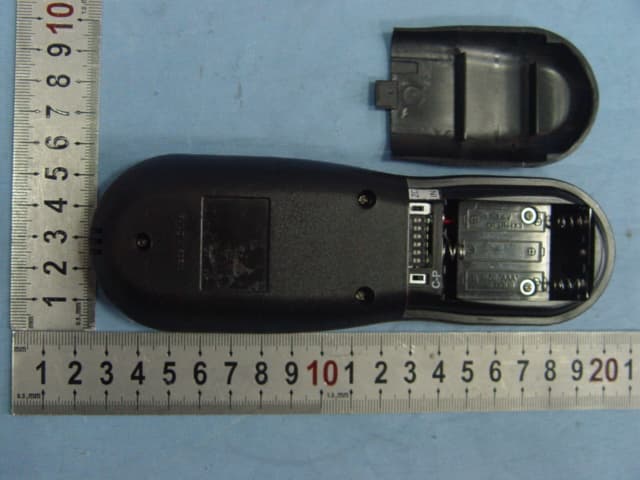
EPK001105A
Oct 23, 2006Johnson Gas RF Model H Version
Equipment Class
DSC - Part 15 Security/Remote Control Transmitter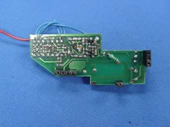
EPK001106A
Sep 26, 2006Fireplace Remote Control
Equipment Class
DSC - Part 15 Security/Remote Control Transmitter