EROCWD1011Wall Type Dimmer
Crestron Electronics IncApplication Details
- Equipment Class
- DTS - Digital Transmission System
- Date of Grant
- Apr 11, 2005
- Application Purpose
- Original Equipment
- Date of Application
- Apr 11, 2005
- Equipment Note
- Wall Type Dimmer
- Frequency Range
- 2405.00000000 - 2475.00000000
- Company
- Crestron Electronics Inc
- Country
- United States
Documents & Files
Document Text
Text extracted from the exhibit documents filed with the FCC. Open a document above to read the original.
Users Manual
CLW-DIM1RF, DIMS1RF, & SLVD1RF(W/A/B) Introduction Specifications Following are specifications for the -DIM1RF, -DIMS1RF, and -SLVD1RF. Features and Functions The CLW-DIM1RF (-DIM1RF) is a stand-alone wall box dimmer that can also act as a wireless Cresnet ® device that reports to a Crestron ® control processor via a wireless gateway such as the Crestron C2N-MNETGW. The CLW -DIM1RF has two preset lighting levels that can be adjusted (refer to note below). The CLW-DIM1RF features an internal antenna for communication with Crestron wireless switches using the 2.4 GHz ISM frequency range. CLW-DIM1RF, CLW-DIMS1RF, & CLS-SLVD1RF Specifications SPECIFICATION DETAILS Power Requirements Line Power, 120 VAC, 60 Hz Operating Frequency 2.4 GHz ISM Default RF ID -DIM1RF: 00 -DIMS1RF: 00 Switch Type Dimmer Load Type Incandescent, Tungsten-Halogen, Magnetic Low Voltage 2-Series Control System Update File 1,2 Version 3.117 or later Load Ratings 3 Incandescent/Tungsten Halogen -DIM1RF: 1000W -DIMS1RF: 1000W -SLVD1RF: N/A Magnetic Low Voltage 4 -DIM1RF: 1000VA/750W -DIMS1RF: 1000VA/750W -SLVD1RF: N/A Operating Temperature and Humidity 32°F to 104°F (0°C to 40°C) 10 to 90% Relative Humidity (Non-Condensing) Dimensions and Weight -DIM1RF and -DIMS1RF: Height: 4.13 in (10.48 cm) Width: 2.38 in (6.03 cm) Depth: 1.88 in (4.77 cm) Weight: 4.9 oz (0.67 kg) -SLVD1RF: Height: 4.13 in (10.48 cm) Width: 1.75 in (4.45 cm) Depth: 1.88 in (4.77 cm) Weight: 3.6 oz (0.50 kg) NOTE: The two preset levels are noted as Preset 1-High and Preset 1- Low. “Preset 1-High” is usually used for turning lights on to full brightness while preset “Preset 1- Low” is usually used for turning the lights off. Although “Preset 1-High” and “Preset 1-Low” are usually used for “On” and “Off” respectively, the light level for each preset can be customized by the user. Refer to “Operating Button and Switch” on page 4 for more information on customizing light levels. The CLW-DIM1RF features a three-position mode selection switch. Refer to “Operating Button and Switch” on page 5 for more information. In the absence of Cresnet communications, the dimmer can still be used to control lighting. The CLW-DIMS1RF (-DIMS1RF) is similar to the - DIM1RF with the added capability of working with a slave unit (CLW-SLVD1RF) in a multi-switch / single circuit application. The CLW-SLVD1RF (-SLVD1RF) is a slave unit that when used in conjunction with the -DIMS1RF acts as an additional dimmer control point in a multi-dimmer / single circuit application. It does not connect to a Cresnet system and cannot be used without a -DIMS1RF. The -SLVD1RF does not have a mode selection switch and is not programmable. It emulates the operation of the -DIMS1RF to which it is connected. 1. The latest software versions can be obtained from the Crestron website. Refer to the NOTE following these footnotes. 2. Crestron 2-Series control systems include the AV2 and PRO2. Consult the latest Crestron Product Catalog for a complete list of 2-Series control systems. 3. Refer to Derating Charts for Multigang Installations on page 3. The -DIM1RF, -DIMS1RF, and -SLVD1RF are available in white, almond, and black. White units are designated by part numbers ending in “W”. Almond units are designated by part numbers ending in “A”. Black units are designated by part numbers ending in “B”. Each dimmer can be covered with a decorative faceplate (not supplied). 4. VA ratings are for input power to the transformer. If you do not know the input power requirement of the transformer, use the bulb’s wattage rating to determine proper rating. NOTE: Crestron software and any files on the website are for Authorized Crestron dealers and Crestron Authorized Independent Programmers (CAIP) only. New users may be required to register to obtain access to certain areas of the site (including the FTP site). Crestron Electronics, Inc. Installation Guide – DOC. 6292 15 Volvo Drive Rockleigh, NJ 07647 02.05 Tel: 888.CRESTRON Fax: 201.767.7576 Specifications subject to www.crestron.com change without notice. CLW-DIM1RF, DIMS1RF, & SLVD1RF(W/A/B) Physical Description Physical view of CLW-SLVD1RF (clockwise from top; Top, Side, and Front) The -DIM1RF and -DIMS1RF contain one large pushbutton, a light emitting diode (LED) with software adjustable brightness*, and a three-position slider-switch, shown after this paragraph. The -SLVD1RF is similar to the -DIM1RF and -DIMS1RF but does not have the slider-switch. Line voltage connections are made at the rear of the dimmer. 1.75 in (4.45 cm) 3.81 in (9.68 cm) 4.13 in (10.48 cm) 3.28 in (8.32 cm) 1.88 in (4.77 cm) 2.70 in (6.86 cm) 1.50 in (3.81 cm) * LED brightness can only be adjusted through Crestron programming software. CLW-DIM1RF/-DIMS1RF (L) and CLW-SLVD1RF (R) shown in white The -DIM1RF, -DIMS1RF, and -SLVD1RF mount in a standard wallbox and are covered using a decorative faceplate (not included). Physical view of CLW-DIM1RF/-DIMS1RF (clockwise from top; Top, Side, and Front) Industry Compliance This unit has been manufactured to comply with UL’s Standards for Safety in Canada and the United States. Formal approval is pending. 1.75 in (4.45 cm) 2.38 in (6.03 cm) 3.28 in (8.32 cm) 3.81 in (9.68 cm) 4.13 in (10.48 cm) 1.88 in (4.77 cm) 2.70 in (6.86 cm) 1.50 in (3.81 cm) Compliance Statement (Part 15.19 ) This device complies with Part 15 of the FCC Rules. Operation is subject to the following two conditions: 1. This device may not cause harmful interference, and 2. This device must accept any interference received, including interference that may cause undesired operation. Warning (Part 15.21 ) Changes or modifications not expressly approved by the party responsible for compliance could void the user’s authority to operate the equipment. RF Exposure (OET Bulletin 65 ) To comply with FCC's RF exposure limits for general population / uncontrolled exposure, the antenna(s) used for this transmitter must be installed to provide a separation distance of at least 20 cm from a…
Text truncated - open the document above for the full version.
Cover Letter(s)
F C C CONFIDENTIALITY Date: February 14, 2005 To: FEDERAL COMMUNICATIONS COMMISSION 7435 Oakland Mills Road Columbia, MD 21046 Subject: Request for Non disclosure for FCC ID: EROCWD1011 To Whom It May Concern: Pursuant to 47 CFR Section 0.459, Crestron Electronics Inc. hereby requests non- disclosure and confidential treatment of the following materials submitted in support of FCC certification application for FCC ID EROCWD1011 a. Schematic Diagrams b. Operational Description c. Block Diagram Above materials contain trade secrets, proprietary and technical information which would customarily be guarded from competitors under 47 CFR section 0.457(d)(2). Disclosure or publication of any portion of this company confidential material to other parties could cause substantial competitive harm and provide unjustified benefits for competitors. Crestron Electronics Inc. understands that pursuant to 47 CFR section 0.457(d)(1)(ii) disclosure of the applicant and all accompanying documentation will not be made before the date of the grant. Sincerely yours, Sudharsan Yogasuntharam Electrical Engineer Crestron Electronics
Cover Letter(s)
F C C A U T H O R I Z A T I O N Date: February 14, 2005 To: FCC Authorization & Evaluation Division 7435 Oakland Mills Road Columbia, MD 21045-0429 From: Sudharsan Yogasuntharam Phone: 201- 750 - 7004x350 Electrical Engineer Fax: 201 - 767 - 5771 Applicant: Crestron Electronics Inc. E-Mail: [email protected] ________________________________________________________________________ Dear Ladies and/or Gentlemen: I appoint Kenneth L. Boston and James Blaha at L.S. Compliance, Inc., to act as an agent in the preparation of applications under Part 15 of the rules and regulations of the Federal Communications Commission. I certify that the exhibitions properly describe the device being submitted under this application and will implement any changes described in the test report. The labels described will be affixed to each item. The following statement is required by the Federal Communications Commission: By checking Yes, the applicant certifies that, in the case of an individual applicant, he or she is not subject to a denial of federal benefits, that included FCC benefits, pursuant to section 5301 of the Anti-Drug Abuse Act of 1988, 21 U.S.C 853(a), or, in the case of a non-individual applicant (e.g. corporation, partnership, or other unincorporated association), no party to the application is subject to a denial of federal benefits, that includes FCC benefits, pursuant to that section. ___X___YES _______NO Dated this 14 h day of February, 2005 By: Sudharsan Yogasuntharam Title: Electrical Engineer Phone: 201 750 7004 x 350
Cover Letter(s)
www.yageo.com 2.45 GHz ISM-band antenna for Bluetooth and WLAN IEEE 802.11b Surface-mount ceramic multilayer antennas Product specification Supersedes data of 27th September 2001 2002 Oct 17 Rev.2 ANTENNA PRODUCTS Phycomp Product specification Surface-mount ceramic multilayer antennas 2.45 GHz ISM-band antenna for Bluetooth and WLAN IEEE 802.11b 2002 Oct 17 Rev.2 2 www.yageo.com (1) Bluetooth is a trademark owned by Telefonieaktiebolaget L M Ericsson, Sweden. FEATURES • Designed for 2.45 GHz ISM-band • Simplifies antenna circuitry • NiSn lead-free terminations • Suitable for wave and reflow soldering • Supplied in tape on reel. APPLICATIONS • Telecommunications • Computing (PCs, printers, PDAs) • Wireless office data communications including WLAN • Consumer electronics (wireless headphones). QUICK REFERENCE DATA DESCRIPTION VALUE Centre frequency (for different central frequency shifts) 2.45, 2.60, 2.70, 2.80 and 2.90 GHz Bandwidth 100 MHz Gain 1.2 dBi max. VSWR 2 max. Polarization Linear Azimuth beamwidth Omni-directional Impedance 50 Ω Power dissipation 1 W Operating temperature −55 to +125 °C Terminations NiSn Resistance to soldering heat 260 °C for 10 s Weight 0.16 g DESCRIPTION This 2.45 GHz ceramic multilayer antenna has been designed to meet the requirements of the Bluetooth TM(1) and IEEE 802.11b wireless communications protocol. It consists of a rectangular block of low-dielectric ceramic material and is fabricated in a water-based non-toxic process. The antenna is capable of providing good connectivity using near 50 Ω microstrip directly onto the PC board. ENVIRONMENTAL CARE The foil making process uses an environment- friendly aqueous-solvent technology that fully complies with today’s green-product design requirements. All terminations are lead-free. Packing materials can be recycled. Phycomp Product specification Surface-mount ceramic multilayer antennas 2.45 GHz ISM-band antenna for Bluetooth and WLAN IEEE 802.11b 2002 Oct 17 Rev.2 3 www.yageo.com MECHANICAL DATA HBK016 S 2 S 1 S 4 S 3 W C G F S 1 G F T L S 4 S 2 S 3 C Fig.1. Dimensional outline. For dimensions see Table 1. Physical dimensions Table 1 Antenna dimensions SYMBOL DETAILS DIMENSIONS (mm) L − 7.35 ±0.25 W − 5.5 ±0.2 T − 1.3 ±0.2 F feed termination 0.9 ±0.25 G optional ground termination (1) 1.25 ±0.35 C − 0.5 ±0.3 S 1 NC solder termination 1.25 ±0.35 S 2 NC solder termination 1.25 ±0.35 S 3 NC solder termination 0.9 ±0.25 S 4 NC solder termination 1.25 ±0.35 Note 1. The antenna has built-in circuitry to the ground termination. Connecting the antenna’s ground point to the system’s RF ground plane is optional. If good matching is achieved, the ground termination is then used as a solder joint (like S 1 , S 2 , S 3 , and S 4 ) to fix the antenna to the substrate only. Device marking CENTRE FREQUENCY (GHz) MARKING CODE 2.45 no marking 2.60 6 2.70 7 2.80 8 2.90 9 Phycomp Product specification Surface-mount ceramic multilayer antennas 2.45 GHz ISM-band antenna for Bluetooth and WLAN IEEE 802.11b 2002 Oct 17 Rev.2 4 www.yageo.com ELECTRICAL CHARACTERISTICS DESCRIPTION VALUE Centre frequency 2.45, 2.60, 2.70, 2.80 and 2.90 GHz Bandwidth 100 MHz Gain 1.2 dBi max. VSWR 2 max. Polarization Linear Azimuth beamwidth Omni-directional Impedance 50 Ω Power dissipation 1 W Operating temperature −55 to +125 °C Terminations NiSn Resistance to soldering heat 260 °C, 10 sec. HBK015 W S 2 C L S 4 S 3 S 1 G F C ANTENNA Dimensions in mm Fig.2 Recommended dimensions of solder lands. For dimensions see Table 2. Physical dimensions Table 2 Recommended solder land pattern SYMBOL COMMENT DIMENSIONS (mm) SYMBOL COMMENT DIMENSIONS (mm) L − 8.30 ±0.10 S 1 NC mounting pad 1.40 ±0.10 W − 5.70 ±0.10 S 2 NC mounting pad 1.40 ±0.10 F feed pad 1.00 ±0.10 S 3 NC mounting pad 1.00 ±0.10 G optional ground pad 1.40 ±0.10 S 4 NC mounting pad 1.40 ±0.10 C − 0.90 ±0.10 − − − FOOTPRINT DIMENSIONS Phycomp Product specification Surface-mount ceramic multilayer antennas 2.45 GHz ISM-band antenna for Bluetooth and WLAN IEEE 802.11b 2002 Oct 17 Rev.2 5 www.yageo.com HBK090 Dimensions in mm 50 Ω transmisson line SMA connector 814 0.8 14 1.2 antenna chip STANDARD TEST BOARD FOR RADIATION PATTERN AND SWR MEASUREMENTS Fig.4 Typical SWR and characteristic impedance measurements. Fig.3 Typical FR4 test board. 2.03.0 f (GHz) SWR 1.0 2.0 3.0 5.0 7.0 6.0 8.0 9.0 10.0 4.0 2.22.42.62.8 RYA002 123 RYA0003 10 25 50 100 250 10 25 50 Ω Ω Ω 100 250 ∞ 0 1025100250 + j − j 2 GHz 3 GHz 2 3 1 Marker data: 1: SWR = 1.28; f = 2.400 GHz 2: SWR = 1.34; f = 2.450 GHz 3: SWR = 1.34; f = 2.500 GHz. Marker data: 1: 50.75 Ω/12.36 Ω; f = 2.400 GHz 2: 44.98 Ω/12.83 Ω; f = 2.450 GHz 3: 43.99 Ω/12.27 Ω; f = 2.500 GHz. Phycomp Product specification Surface-mount ceramic multilayer antennas 2.45 GHz ISM-band antenna for Bluetooth and WLAN IEEE 802.11b 2002 Oct 17 Rev.2 6 www.yageo.com RYA005 180° −90°90° 0° −40−30−20−100 dBi RYA004 180° −90° 90° 0° −40−30−20−100 dBi Fig.5 Typical radiation patterns. APPLICATION EXAMPLE HBK014 8 8 82 GROUND PLANE (on back side) BLUETOOTH OR OTHER RF MODULE CLEARANCE (no ground plane) CLEARANCE (no ground plane) ANTENNA CHIP Ground Feedpoint 50 Ω transmisson line (can be a straight connection) Fig.6 Suggested layout. Dimensions in mm. The ground termination can be optionally connected to RF ground. E-plane H-plane (omni-directional) Phycomp Product specification Surface-mount ceramic multilayer antennas 2.45 GHz ISM-band antenna for Bluetooth and WLAN IEEE 802.11b 2002 Oct 17 Rev.2 7 www.yageo.com ORDERING INFORMATION Components may be ordered by using either a simple 15-digit clear text code or Phycomp’s unique 12NC. Ordering example for a Type 290 antenna, 1000 pieces supplied in blister tape on 180 mm reel. Clear text code E XAMPLE: AN2900000707051K DESCRIPTION CODE ORDERING EXAMPLE Product AN = antenna type AN Centre frequency 2450 = 2.45 GHz 2800 = 2.80 GHz 2600 = 2.60 GHz 2900 = 2.90 GHz 2700 = 2.70 GHz 2900 Bandwidth 00 = 100 MHz 00 Material 07 = K7 07 Size …
Text truncated - open the document above for the full version.
External Photos
Crestron Electronics, Inc. Wall Box Dimmer 2.405 – 2.480 GHz FCC ID: EROCWD1011 Photo One – External Wall Box Dimmer to Control Room Lighting Crestron Electronics, Inc. Wall Box Dimmer 2.405 – 2.480 GHz FCC ID: EROCWD1011 Photo Two – External Wall Box Dimmer Manual Control Switch Crestron Electronics, Inc. Wall Box Dimmer 2.405 – 2.480 GHz FCC ID: EROCWD1011 Photo Three – External Wall Box Dimmer Electrical Wiring Crestron Electronics, Inc. Wall Box Dimmer 2.405 – 2.480 GHz FCC ID: EROCWD1011 Photo Four – External FCC ID Label
Internal Photos
Crestron Electronics, Inc. Wall Box Dimmer 2.405 – 2.480 GHz FCC ID: EROCWD1011 Photo One – Internal Front Panel Removed – RF PCB Exposed Crestron Electronics, Inc. Wall Box Dimmer 2.405 – 2.480 GHz FCC ID: EROCWD1011 Photo Two – Internal RF PCB Removed from Dimmer Box Crestron Electronics, Inc. Wall Box Dimmer 2.405 – 2.480 GHz FCC ID: EROCWD1011 Photo Three – Internal RF PCB Close-Up – Component Side Crestron Electronics, Inc. Wall Box Dimmer 2.405 – 2.480 GHz FCC ID: EROCWD1011 Photo Four – Internal RF Antenna Close Up Crestron Electronics, Inc. Wall Box Dimmer 2.405 – 2.480 GHz FCC ID: EROCWD1011 Photo Five – Internal RF PCB Flip Side with Insulating Material
RF Exposure Info
Prediction of MPE limit at a given distance Equation from page 18 of OET Bulletin 65, Edition 97-01 where:S = power density P = power input to the antenna G = power gain of the antenna in the direction of interest relative to an isotropic radiator R = distance to the center of radiation of the antenna Maximum peak output power at the antenna terminal:12.44(dBm) Maximum peak output power at the antenna terminal:17.53880502(mW) Antenna gain(typical):1.2(dBi) Maximum antenna gain:1.318256739(numeric) Prediction distance:20(cm) Prediction frequency:2450(MHz) MPE limit for uncontrolled exposure at prediction frequency:1(mW/cm^2) Power densit y at prediction frequency:0.004600(mW/cm^2) 2 4R PG S π =
Test Report
L.S. Compliance, Inc. W66 N220 Commerce Court Cedarburg, WI 53012 262-375-4400 Fax: 262-375-4248 COMPLIANCE TESTING OF: CLW-DIM1RF Stand Alone Wall Box Dimmer RF Module PREPARED FOR: Crestron Electronics Attn.: Mr. Paul Connell 15 Volvo Drive Rockleigh, NJ 07647 TEST REPORT NUMBER: 304556 TEST DATE(S): February, March and April, 2005 All results of this report relate only to the items that were tested. This report is not to be reproduced, except in full, without written approval of L. S. Compliance, Inc. L.S. Compliance, Inc. Page 2 of 34 Test Report Number: 304556 Prepared For: Crestron Electronics Table of Contents Section Description Page Index 2 1 L. S. Compliance in Review 3 2 A2LA Certificate of Accreditation 4 3 A2LA Scope of Accreditation 5 4 Validation Letter-U.S. Competent Body for EMC Directive 89/336/EEC 6 5 Signature Page 7 6 Product and General Information 8 7 Introduction 8 8 Product Description 8 9 Test Requirements 9 10 Summary of Test Report 9 11 Radiated Emissions Test 10-18 12 Conducted Emissions Test, AC Power Line 19-23 13 Conducted Emissions Test, Power Output 24-25 14 Conducted Emissions Test, Spurious Emissions 26-27 15 Conducted Emissions Test, Occupied Bandwidth 28-30 16 Conducted Emissions Test, Spectral Density 31-33 Appendix A Test Equipment List 34 L.S. Compliance, Inc. Page 3 of 34 Test Report Number: 304556 Prepared For: Crestron Electronics 1. L. S. Compliance In Review L.S. Compliance - Accreditations and Listing’s As an EMC Testing Laboratory, our Accreditation and Assessments are recognized through the following: A2LA – American Association for Laboratory Accreditation Accreditation based on ISO/IEC 17025 : 1999 with Electrical (EMC) Scope of Accreditation A2LA Certificate Number: 1255.01 Federal Communications Commission (FCC) – USA Listing of 3 Meter Semi-Anechoic Chamber based on Title 47 CFR – Part 2.948 FCC Registration Number: 90756 Listing of 3 and 10 meter OATS based on Title 47CFR – Part 2.948 FCC Registration Number: 90757 Industry Canada On file, 3 Meter Semi-Anechoic Chamber based on RSS-212 – Issue 1 File Number: IC 3088-A On file, 3 and 10 Meter OATS based on RSS-212 – Issue 1 File Number: IC 3088 U. S. Conformity Assessment Body (CAB) Validation Validated by the European Commission as a U. S. Competent Body operating under the U. S. /EU, Mutual Recognition Agreement (MRA) operating under the European Union Electromagnetic Compatibility –Council Directive 89/336/EEC, Article 10.2. Date of Validation: January 16, 2001 Validated by the European Commission as a U.S. Notified Body operating under the U.S./EU, Mutual Recognition Agreement (MRA) operating under the European Union Telecommunication Equipment – Council Directive 99/5/EC, Annex V. Date of Validation: November 20, 2002 Notified Body Identification Number: 1243 L.S. Compliance, Inc. Page 4 of 34 Test Report Number: 304556 Prepared For: Crestron Electronics 2. A2LA Certificate of Accreditation L.S. Compliance, Inc. Page 5 of 34 Test Report Number: 304556 Prepared For: Crestron Electronics 3. A2LA Scope of Accreditation L.S. Compliance, Inc. Page 6 of 34 Test Report Number: 304556 Prepared For: Crestron Electronics 4. Validation Letter – U.S. Competent Body for EMC Directive 89/336/EEC L.S. Compliance, Inc. Page 7 of 34 Test Report Number: 304556 Prepared For: Crestron Electronics 5. Signature Page Prepared By: April 8 th , 2005 Teresa A. White, Document Coordinator Date Tested and Approved By: April 8 th , 2005 Kenneth L. Boston, EMC Lab Manager Date PE #31926 Licensed Professional Engineer Registered in the State of Wisconsin, United States L.S. Compliance, Inc. Page 8 of 34 Test Report Number: 304556 Prepared For: Crestron Electronics 6. Product and General Information Manufacturer: Crestron Electronics Date(s) of Test: February, March and April of 2005 Test Engineer(s): Tom Smith Abtin Spantman √ Ken Boston Model #: CLW-DIM1RF Serial #: X101357 Voltage: 115 VAC Operation Mode: Continuous data modulation transmit 7. Introduction During February, March and April of 2005, a series of Conducted and Radiated Emission tests were performed on one sample of the Crestron Stand Alone wall box dimmer RF module, Model Number CLW-DIM1RF, Serial Number X101357, here forth referred to as the “Equipment Under Test” or “EUT”. These tests were performed using the procedures outlined in ANSI C63.4-2003 for intentional radiators, and in accordance with the limits set forth in FCC Part 15.247 (Industry Canada RSS-210) for a low power transmitter. These tests were performed by Kenneth L. Boston, EMC Lab Manager of L.S. Compliance, Inc. Direct conducted RF measurements for this product were transposed from the Crestron PCB Test Report # 304557 for two reasons. First, the RF section of both the Crestron dimmer and the PCB are identical, and second, a direct connection to the output of the dimmer cannot be accomplished due to the power supply configuration on the A.C. circuit. All Radiated and Conducted Emission tests were performed upon the EUT to measure the emissions in the frequency bands described in Title 47 CFR, FCC Part 15, including 15.35, 15.209, 15.247 and Industry Canada RSS-210 to determine whether these emissions are below the limits expressed within the standards. These tests were performed in accordance with the procedures described in the American National Standard for methods of measurement of Radio- Noise Emissions from Low-Voltage Electrical and Electronic Equipment in the Range of 9 kHz to 40 GHz (ANSI C63.4-2003). Another document used as a reference for the EMI Receiver specification was the Comite International Special Des Perturbations Radioelelectriques (CISPR) Number 16-1, 2003. All tests were performed at L.S. Compliance, Inc., in Cedarburg, Wisconsin, unless otherwise noted. 8. Product Description The CLW-DIM1RF is a stand alone wall box dimmer, used in standard 110 VAC residential or commercial wiring applications with load ratings up to 1000 Watts. The CLW-DIM1RF is designe…
Text truncated - open the document above for the full version.
Contact Information
Applicant
Chirag Patel(Lead Compliance Engineer)
Test Firm
L. S. Compliance, Inc.James Blaha
262-375-4400Fax: 262-375-4248
Technical Specifications
| # | Rule Parts | Frequency Range | Power Output |
|---|---|---|---|
| 1 | 15C | 2.40 GHz - 2.48 GHz | 17.60 mW |
Other Applications from Crestron Electronics Inc
EROTSW1580
Jan 29, 202615 inch Touch Screen wall mount
Equipment Class
6XD - 15E 6 GHz Low Power Indoor Client
EROM202108007
Sep 19, 2023Crestron Video Bar with WIFI and Bluetooth
Equipment Class
NII - Unlicensed National Information Infrastructure TX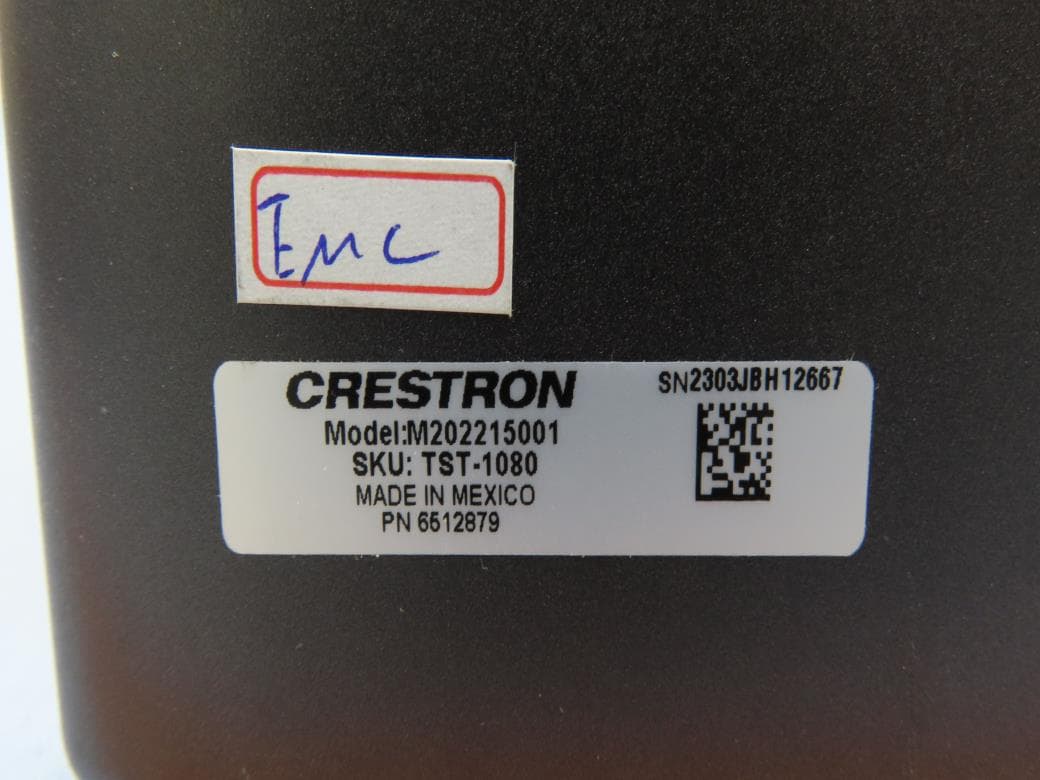
EROM202215001
Jul 05, 202310.1 in. Wireless Touch Screen
Equipment Class
DSS - Part 15 Spread Spectrum Transmitter
EROAM-TX3-200
Jan 13, 2023WIRELESS MEDIA TRANSMITTER
Equipment Class
NII - Unlicensed National Information Infrastructure TX
EROAM-TX3
Jun 06, 2021Wireless Media Transmitter
Equipment Class
DTS - Digital Transmission System