EROCWD66712.4GHz RF Wireless Transceiver
Crestron Electronics Inc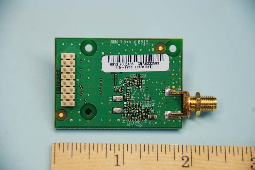
Click to zoom
Application Details
- Equipment Class
- DTS - Digital Transmission System
- Date of Grant
- Apr 28, 2009
- Application Purpose
- Original Equipment
- Date of Application
- Apr 28, 2009
- Equipment Note
- 2.4GHz RF Wireless Transceiver
- Frequency Range
- 2405.00000000 - 2480.00000000
- Company
- Crestron Electronics Inc
- Country
- United States
Documents & Files
Document Text
Text extracted from the exhibit documents filed with the FCC. Open a document above to read the original.
Users Manual
Crestron CWD6671 Two-Way RF Transceiver Module Operations Guide This document was prepared and written by the Technical Documentation department at: Crestron Electronics, Inc. 15 Volvo Drive Rockleigh, NJ 07647 1-888-CRESTRON All brand names, product names and trademarks are the property of their respective owners. ©2009 Crestron Electronics, Inc. Crestron CWD6671 Two-Way RF Transceiver Module Contents Two-Way RF Transceiver Module: CWD6671..............................................1 Introduction...............................................................................................................................1 Functions and Features................................................................................................1 Specifications..............................................................................................................2 Physical Description....................................................................................................2 Industry Compliance...................................................................................................4 Setup..........................................................................................................................................7 Hardware Hookup.......................................................................................................7 End Product Labeling..................................................................................................8 Documentation............................................................................................................8 Operations Guide - DOC. 6834 Contents • i Crestron CWD6671 Two-Way RF Transceiver Module Two-Way RF Transceiver Module: CWD6671 Introduction Functions and Features The CWD6671 (hereafter referred to as “module”) is a two-way radio frequency (RF) module that utilizes the 2.4 GHz frequency band to communicate with other devices. The module operates according to the IEEE 802.15.4 specification and can be configured to minimize the possibility of interference with other devices. The module receives RF signals from one or more Crestron devices and can transmit these signals over the air or over a cable run for further processing (depending on the application). Functional Summary • Two-way RF transceiver − 2.4 GHz frequency band, IEEE 802.15.4 specification − Range from 3 feet to 50 ft. − Operates on one of sixteen available channels to establish optimal si gnal quality The transceiver uses a 3.8 milliwatt signal that can travel up to approximately 50 feet indoors. The range is dependent on the construction of the building, obstructions, and RF interference from other devices. The location of the module and the orientation of its antenna are also important factors in determining RF performance. Operations Guide - DOC. 6834 Two-Way RF Transceiver Module: CWD6671 • 1 Two-Way RF Transceiver Module Crestron CWD6671 Specifications The table below is a summary of specifications for the CWD6671. Specifications of the CWD6671 SPECIFICATION DETAILS Power Requirements 0.22 Watts (3.3VDC @ 0.67A) Operating Frequency 2400 MHz to 2483.5 MHz (802.15.4 compliant) Operating Ranges¹ Minimum Distance Maximum Distance Indoors (without repeater device) 3 ft 50 ft Available Channels 16 (numbered 11 through 26 per 802.15.4) RF Output Power 3.8 mW Serial Communications SPI, 3.3V Nominal Antenna Connector SMA Reverse Polarity Female Connector with ¼-36 UNS2B Screw Dimensions Width: 1.35 in (3.43 cm) Height: 2.4 in (6.10 cm) Depth: 0.75 in (1.91 cm) 1. The location of the module and the orientation of the antenna are important factors in the RF performance. With the unit located outside of any metal enclosures, the antenna is adjusted to achieve the best range. The range is dependent on its placement and the building in which it is used. The construction of the building, obstructions, and RF interference from other devices are factors determining the effective range of the unit. To prevent unit-to-unit RF interference, multiple modules operating at the same frequencies should not be installed within 3-5 feet of each other. Physical Description The module, shown below, consists of various components attached to a printed circuit board. A SMA reverse polarity female antenna port is located at edge of the circuit board for attaching a dipole antenna while a 16-pin header is for the application-specific installation. Physical View of CWD6671 2 • Two-Way RF Transceiver Module: CWD6671 Operations Guide - DOC. 6834 Crestron CWD6671 Two-Way RF Transceiver Module CWD6671 Detail Views 1.90 in (4.83 cm) 1.35 in (3.43 cm) PIN 2 PIN 1 PIN 16 PIN 15 Ports The module contains a 16-pin header, a 10-pin debug header, and one antenna port. Refer to the diagrams and descriptions that follow. Power/I-O The 16 pin header provides power to the module as well as serial communications between the module and wired devices. Refer to the following table for pin assignments of the module interface connector. PIN 16 PIN 15 PIN 2 PIN 1 468101214 13 11 9 7 53 Power/I-O Pinout Signals Pin # Signal Pin # Signal 1 +5V (NU) 9 SSEL_INT 2 GND 10 GND 3 +5V (NU) 11 SCLK 4 WAKE 12 GND 5 +3.3V 13 MISO 6 Link Activity 14 MOSI 7 3.3V 15 GND 8 HOST_INT 16 RF_RESET_N Operations Guide - DOC. 6834 Two-Way RF Transceiver Module: CWD6671 • 3 Two-Way RF Transceiver Module Crestron CWD6671 Antenna This SMA reverse polarity female antenna port is located at edge of the circuit board for attaching the included dipole antenna. APPROVED ANTENNAS: The CWD6671 antenna interface has a unique coupling designed to ensure that no antenna other than the one supplied shall be used with the device. Replacement antennas may be purchased from Crestron according to the following description: Part Number: 2001016 Description: ANTENNA, 2400.00MHZ, DIPOLE, SMA, REVERSE POLARITY, FEMALE Industry Compliance Labeling Requirements If the FCC ID on the CWD6671 is not visible when the module is …
Text truncated - open the document above for the full version.
Cover Letter(s)
Crestron Electronics, Inc. 15 Volvo Drive Rockleigh, NJ 07647 Tel: 800.237.2041/ 201.767.3400 Fax: 201.767.7576 www.crestron.com April 18, 2009 Compliance Certification Services Certification Division 47173 Benicia Street Fremont, CA 94538, USA Subject: FCC Certification Application FCC ID: EROCWD6671 To whom it may concern: I, the undersigned, hereby authorize Ms. Claire Hoque/Application Examiner of Compliance Engineering Services, Inc., d.b.a. Compliance Certification Services and hereafter referred to as CCS, to act on our behalf in all manners relating to application for equipment authorization, including signing of all documents relating to these matters. Any and all acts carried out by Ms. Claire Hoque of CCS on our behalf shall have the same effect as acts of our own. I, the undersigned, hereby certify that we are not subject to a denial of federal benefits, that includes FCC benefits, pursuant to Section 5301 of the Anti-Drug Abuse Act of 1988, 21 U.S.C. 853(a). In authorizing CCS as our agent, we still recognize that we are responsible to: a) comply with the relevant provisions of the certification program; b) make all necessary arrangements for the conduct of the evaluation, including provision for examining documentation and access to all areas, records (including internal audit reports) and personnel for the purposes of evaluation (e.g. testing, inspection, assessment, surveillance, reassessment) and resolution of complaints; c) make claims regarding certification only in respect of the scope for which certification has been granted; d) do not use our product certification in such a manner as to bring the Certification Division into disrepute and not make any statement regarding our product certification which the Certification Division may consider misleading or unauthorized; e) upon suspension or cancellation of certification, discontinue use of all advertising matter that contains any reference thereto and return any certification documents as required by the Certification Division; f) use certification only to indicate the products are certified as being in conformity with specified standards; g) endeavor to ensure that no certificate or report nor any part thereof is used in a misleading manner; h) ensure that any reference to our product certification in communication media such as documents, brochures or advertising, complies with the requirements of the Certification Division; i) keep a record of all complaints made known to the us relating to the product’s compliance with requirements of the relevant standard and to make these records available to the Certification Division when requested; j) take appropriate action with respect to such complaints and any deficiencies found in products or services that affect compliance with the requirements for certification; k) document the actions taken. This authorization is valid for the above-referenced application. Sincerely Yours, Crestron Electronics Inc. Grace Lin Sr. Compliance Engineer Email: [email protected] Telephone: 201-750-7004 extension 11464
Cover Letter(s)
Crestron Electronics, Inc. 15 Volvo Drive Rockleigh, NJ 07647 Tel: 800.237.2041/ 201.767.3400 Fax: 201.767.7576 www.crestron.com April 18, 2009 Federal Communications Commission 7435 Oakland Mills Road Columbia MD 21046 Subject: Request for Confidentiality FCC ID: EROCWD6671 To Whom It May Concern: Pursuant to the provisions of Sections 0.457 and 0.459 of the Commission’s rules (47 CFR §§ 0.457, 0.459), we are requesting the Commission to withhold the following attachments as confidential document from public disclosure indefinitely. Schematic Diagram Block Diagram Theory of Operation Above mentioned document contains detailed system and equipment description are considered as proprietary information in operation of the equipment. The public disclosure of above documents might be harmful to our company and would give competitor an unfair advantage in the market. It is our understanding that all measurement test reports, FCC ID label format and correspondent during certification review process cannot be granted as confidential documents and those information will be available for public review once the grant of equipment authorization is issued. Best Regards Crestron Electronics Inc. Grace Lin Grace Lin Sr. Compliance Engineer Email: [email protected] Telephone: 201-750-7004 extension 11464
External Photos
FCC ID: EROCWD6671 IC: 5683C-CWD6671 External Photos Page 1 of 2 External Photos FCC ID: EROCWD6671 IC: 5683C-CWD6671 External Photos Page 2 of 2
ID Label/Location Info
REVNAMEDESCRIPTIONDATE BRAORIGINAL ISSUE PER EWO155304-09-09 BRBTEXT REVISIONS04-23-09 APPROVED REVISIONS SIZEPRINT NUMBERREV A271785A SCALE:1:1SHEET:1 OF 1FILE:271785-B 6503173PMC2 FINISHED GOODS SORT NAME USED ON UNLESS OTHERWISE SPECIFIED: ALL DIMENSIONS ARE IN INCHES TOLERANCES ARE: FRACTIONS ±1/64 ANGLES ±1/2° DECIMALS .XX±.010 .XXX±.005 NAMEDATE DESIGN BYJH DRAWN BYBR 03-20-09 04-09-09 CHECKED APPROVED THIS DRAWING IS THE EXCLUSIVE PROPERTY OF CRESTRON ELECTRONICS, INC. DISCLOSURE OR REPRODUCTION IN WHOLE OR PART, WITHOUT PRIOR WRITTEN PERMISSION, IS PROHIBITED EXCEPT FOR THE MANUFACTURE OF ARTICLES FOR CRESTRON. LABEL, FCC ID DEBURR & BREAK ALL SHARP EDGES ALL PARTS & PROCESSES MUST BE RoHS COMPLIANT (201) 750-7004 22 LINK DRIVE, ROCKLEIGH, N.J. 07647 FAX (201) 767-5772 NOTES: 1. MATERIAL: UL/CSA APPROVED MATTE FINISHED WHITE POLYESTER, .002” THK WITH PERMANENT ACRYLIC ADHESIVE. 2. PRINT: TEXT AND GRAPHICS - BLACK. 3. USE ARTWORK 24305-B.FMT, IN ONE OF IT’S ORIGINAL, AVAILABLE FORMATS FOR ACTUAL PRODUCTION OF THIS ARTWORK. FCC ID: EROCWD6671 MODEL: CWD6671 IC:5683C-CWD6671 SEE MANUAL 1.00 0.50 R0.06 Preliminary
Test Report
Crestron Electronics, Inc. 15 Volvo Drive Rockleigh, NJ 07647 Tel: 800.237.2041/ 201.767.3400 Fax: 201.767.7576 www.crestron.com DUTY CYCLE CORRECTION FACTOR FOR RADIATED SPURIOUS EMISSIONS April 17, 2009 Re. FCC ID: EROCW06671 IC: 5683C-CWD6671 This product uses an 802.15.4 compliant stack located in Ember integrated circuit EM260-RTR. As specified in “Tips for FCC certification on the EM250 or EM260” (http://portal.ember.com/node/959) which directly applies to the EM260-RTR, and as supported by the Ember data summarized below, the worst case amount of time in the TX Mode in any 100ms window is 27%. A 27% Duty Cycle correction factor is therefore applied to the measured radiated spurious emissions results (effectively a -11dB reduction); 20 * LOG (0.27) = 11.373 dB. Summary: Transmit Power Duty Cycle Version 1.2 Date of Release 6/28/2007 Network TX Duty Cycle (On /total) 25.45% Calculated Network Performance Alternative calculation Max radio throughput 250000 bps Measured throughput single hop 66816 bps Max test network results 44544 (packet payload) Network TX Duty Cycle (On /total) 26.73% Measured Network Performance Use for FCC Calculations 27% In TX Mode 27ms worst case in any 100ms window. Steven Feldman Steven Feldman Chief Engineer Crestron Electronics, Inc
Test Setup Photos
FCC ID: EROCWD6671 IC: 5683C-CWD6671 Test Setup Photos Page 1 of 3 Test Setup Photos Conducted Emission Configuration Photographs Worst-case conducted emission, front view FCC ID: EROCWD6671 IC: 5683C-CWD6671 Test Setup Photos Page 2 of 3 Test Setup Photos Conducted Emission Configuration Photographs Worst-case conducted emission, Side view FCC ID: EROCWD6671 IC: 5683C-CWD6671 Test Setup Photos Page 3 of 3 Test Setup Photos Radiated Emission Configuration Photographs Worst-case radiated emission, front view Worst-case radiated emission, rear view
Contact Information
Applicant
Chirag Patel(Lead Compliance Engineer)
Test Firm
Crestron Electronics, Inc.Mairaj Hussain
[email protected]201-750-7004
Technical Specifications
| # | Rule Parts | Frequency Range | Power Output |
|---|---|---|---|
| 1 | 15C | 2.40 GHz - 2.48 GHz | 3.84 mW |
Other Applications from Crestron Electronics Inc
EROTSW1580
Jan 29, 202615 inch Touch Screen wall mount
Equipment Class
6XD - 15E 6 GHz Low Power Indoor Client
EROM202108007
Sep 19, 2023Crestron Video Bar with WIFI and Bluetooth
Equipment Class
NII - Unlicensed National Information Infrastructure TX
EROM202215001
Jul 05, 202310.1 in. Wireless Touch Screen
Equipment Class
DSS - Part 15 Spread Spectrum Transmitter
EROAM-TX3-200
Jan 13, 2023WIRELESS MEDIA TRANSMITTER
Equipment Class
NII - Unlicensed National Information Infrastructure TX
EROAM-TX3
Jun 06, 2021Wireless Media Transmitter
Equipment Class
DTS - Digital Transmission System