EROCWD6782Two-Way RF Transceiver Module
Crestron Electronics Inc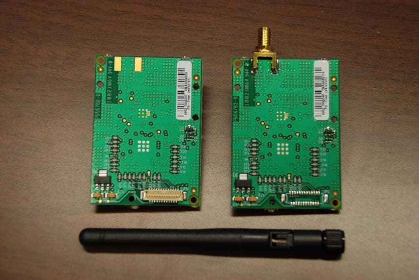
Click to zoom
Application Details
- Equipment Class
- DTS - Digital Transmission System
- Date of Grant
- Jun 10, 2010
- Application Purpose
- Original Equipment
- Date of Application
- May 12, 2010
- Equipment Note
- Two-Way RF Transceiver Module
- Frequency Range
- 2405.00000000 - 2480.00000000
- Company
- Crestron Electronics Inc
- Country
- United States
Documents & Files
Document Text
Text extracted from the exhibit documents filed with the FCC. Open a document above to read the original.
Users Manual
Crestron CWD6782 Two-Way RF Transceiver Module Operations Guide This document was prepared and written by the Technical Documentation department at: Crestron Electronics, Inc. 15 Volvo Drive Rockleigh, NJ 07647 1-888-CRESTRON Regulatory Compliance Federal Communications Commission (FCC) Compliance Statement This device complies with part 15 of the FCC Rules. Operation is subject to the following conditions: (1) This device may not cause harmful interference and (2) this device must accept any interference received, including interference that may cause undesired operation. CAUTION: Changes or modifications not expressly approved by the manufacturer responsible for compliance could void the user’s authority to operate the equipment. NOTE: This equipment has been tested and found to comply with the limits for a Class B device, pursuant to part 15 of the FCC Rules. These limits are designed to provide reasonable protection against harmful interference in a residential installation. This equipment generates, uses and can radiate radio frequency energy and if not installed and used in accordance with the instructions, may cause harmful interference to radio communications. However, there is no guarantee that interference will not occur in a particular installation. If this equipment does cause harmful interference to radio or television reception, which can be determined by turning the equipment off and on, the user is encouraged to try to correct the interference by one or more if the following measures: • Reorient or relocate the receiving antenna • Increase the separation between the equipment and receiver • Connect the equipment into an outlet on a circuit different from that to which the receiver is connected • Consult the dealer or an experienced radio/TV technician for help Industry Canada (IC) Compliance Statement Operation is subject ot the following two conditions: 1. This device may not cause interference, and 2. This device must accept any interference, including interference that may cause undesired operation of the device. To satisfy RF exposure requirements, this device and its antenna must operate with a separation distance of at least 20 centimeters from all persons and must not be colocated or operating in conjunction with any other antenna or transmitter. All brand names, product names and trademarks are the property of their respective owners. ©2010 Crestron Electronics, Inc. Crestron CWD6782 Two-Way RF Transceiver Module Operations Guide - DOC. 7069A Contents • i Contents Two-Way RF Transceiver Module: CWD6782 ..............................................1 Functions and Features .............................................................................................................. 1 Specifications............................................................................................................................. 2 Physical Description – CWD6782 with a SMD Antenna .......................................................... 3 Physical Description – CWD6782 with a Dipole Antenna ........................................................ 5 Setup .......................................................................................................................................... 7 Labeling ..................................................................................................................................... 7 Documentation........................................................................................................................... 8 Crestron CWD6782 Two-Way RF Transceiver Module Operations Guide - DOC. 7069A Two-Way RF Transceiver Module: CWD6782 • 1 • 2.4 GHz frequency band, IEEE 802.15.4 specification • Range from 3 feet to 550 ft. • Operates on one of sixteen available channels to establish optimal signal quality Two-Way RF Transceiver Module: CWD6782 Functions and Features The CWD6782 (hereafter referred to as “module”), with a dipole antenna or an integrated SMD antenna, is a two-way radio frequency (RF) module that utilizes the 2.4 GHz frequency band to communicate with other devices. The module operates according to the IEEE 802.15.4 specification and can be configured to minimize the possibility of interference with other devices. The module receives RF signals from one or more Crestron devices and can transmit these signals over the air for further processing (depending on the application). Functional Summary Two-Way RF Transceiver Module Crestron CWD6782 2 • Two-Way RF Transceiver Module: CWD6782 Operations Guide - DOC. 7069A Specifications The table below is a summary of specifications for the CWD6782. Specifications of the CWD6782 SPECIFICATION DETAILS Power Requirements 1.3 Watts (5VDC @ 0.26A) Operating Frequency 2400 MHz to 2483.5 MHz (802.15.4 compliant) Operating Ranges* Minimum Distance Maximum Distance Indoors (without repeater device) 3 ft 550 ft Available Channels 16 (numbered 11 through 26 per 802.15.4) Antenna Gain: 2.0±0.5 dBi max. Type: Sleeve Dipole Antenna Frequency: 2.4GHz to 2.5 GHz Connector Type: SMA Plug Reverse Polarity Connector with ¼-36 UNS2B Screw Antenna Max. Gain: 1.8 dBi Average Gain: -1.9 dBi Type: SMD Frequency: 2.4GHz to 2.5 GHz Dimensions Width: 1.80 in (4.572 cm) Height: 2.50 in (6.35 cm) Depth: 0.45 in (1.143 cm) * The location and orientation of the module are important factors in the RF performance. With the unit located outside of any metal enclosures, the antenna is adjusted to achieve the best range. The range is dependent on its placement and the building in which it is used. The construction of the building, obstructions, and RF interference from other devices are factors determining the effective range of the unit. To prevent unit-to-unit RF interference, multiple modules operating at the same frequencies should not be installed within 3-5 feet of each other. Crestron CWD6782 Two-Way RF Transceiver Module Operations Guide - DOC. 7069A Two-Way RF Transceiver Module: CWD6782 • 3 Phy…
Text truncated - open the document above for the full version.
External Photos
FCC ID: EROCWD6782 IC: 5683C-CWD6782 External Photos Page 1 of 1 External Photos
ID Label/Location Info
REVISIONS NAME REV DESCRIPTION DATE APPROVED JH A ORIGINAL ISSUE PER EWO1509 10/26/09 22 LINK DRIVE, ROCKLEIGH, N.J. 07647 (201) 750-7004 FAX (201) 767-5772 NAME DATE DRAWN BY CHECKED FINISHED GDS DESIGNED BY SIZE PRINT NUMBER REV LABEL, CUSTOM, FCC ID, CWD 6782 POLYESTER, APPX: .60 X .30 X .002 B 272315 UNLESS OTHERWISE SPECIFIED:ALL DIMENSIONS ARE IN INCHESTOLERANCES ARE:FRACTIONS 1/64 ANGLES ½ DECIMALS .XX .01 .XXX .005 ±± ° ±± THIS DRAWING IS THE EXCLUSIVE PROPERTY OF CRESTRON ELECTRONICS, INC. DISCLOSURE OR REPRODUCTION IN WHOLE OR IN PART, WITHOUT PRIOR WRITTEN PERMISSION, IS PROHIBITED EXCEPT FOR THE MANUFACTURE OF ARTICLES FOR CRESTRON. USED ON SORT NAME 1:1 APPROVED WF 2/9/10 DEBURR & BREAK ALL SHARP EDGES JH 10/26/09 JH 10/26/09 6503621 CLW-EXPEX-GD-W-T SCALE: 272315-A.CDR FILE: SHEET 1 OF 1 A ALL PARTS & PROCESSES MUST BE COMPLIANT RoHS NOTES:1. MATERIAL: WHITE POLYESTER, .002” THK WITHPERMANENT ADHESIVE BACKING.2. PRINT: TEXT AND GRAPHICS - BLACK.3. USE ARTWORK 24863, IN ONE OF IT’SORIGINAL, AVAILABLE FORMATS (THE 272315DRAWING IS A REPRESENTATION OF THEARTWORK, SEE THE ACTUAL ARTWORK DRAWINGFOR THE CORRECT INFORMATION)4. TOLERANCE +/- .010 EXCEPT WHERE NOTEDOTHERWISE. B TW PER ECN 4/12/10 IC: 5683C-CWD6782 MODEL: CWD6782 FCC ID: EROCWD6782 0.300 0.600 R.030
ID Label/Location Info
FCC ID: EROCWD6782 IC: 5683C-CWD6782 ID Label Location Page 1 of 1 ID Label Location
Internal Photos
FCC ID: EROCWD6782 IC: 5683C-CWD6782 Internal Photo Page 1 of 1 Internal Photos
RF Exposure Info
FCC ID: EROCWD6782 IC: 5683C-CWD6782 Page 1 of 1 Maximum Permissive Exposure Performance Criterion: The human RF exposure limit is 1 mW/cm 2 . Evaluation Results: Complies Details: The maximum permissible exposure (MPE) is predicted by using Equation (3) of Section 2 of FCC OET Bulletin 65, Edition 97-01: S = PG/4πR 2 where: S = power density (in appropriate units, e.g. mW/cm 2 ) P = power input to the antenna (in appropriate units, e.g., mW) G = power gain of the antenna in the direction of interest relative to an isotropic radiator R = distance to the center of radiation of the antenna (appropriate units, e.g., cm) P = 119.124 mW, G = 1.585 (2 dBi), R = 20 cm S = 0.0376 mW/cm 2 = 0.376 W/m 2 MPE limit for uncontrolled exposure at prediction frequency: 1 mW/cm 2 Maximum allowable antenna gain: 16.3 dBi Margin of Compliance at 20 cm = 14.3 dB
Test Report
FCC ID: EROCWD6782 IC: 5683C-CWD6782 Page 1 of 33 Test Report FCC Part 15, Subpart C, Section 15.247 Industry Canada RSS-210, Issue 7 Report Number: CWD6782-Cert Model: CWD6782 FCC ID: EROCWD6782 IC: 5683C-CWD6782 Date: May 13, 2010 Prepared by: Grace Lin Date: May 13, 2010 Grace Lin, Sr. Compliance Engineer Reviewed by: Wayne Owens Date: May 13, 2010 Wayne Owens, Director of Program Management FCC ID: EROCWD6782 IC: 5683C-CWD6782 Page 2 of 33 Table of Contents 1. GENERAL DESCRIPTION ................................................................................................ 3 1.1 P RODUCT DESCRIPTION................................................................................................... 3 1.2 TEST METHODOLOGY...................................................................................................... 3 1.3 TEST FACILITY................................................................................................................. 3 1.4 TEST EQUIPMENT............................................................................................................. 4 1.5 E VALUATION SUMMARY.................................................................................................. 4 2. SYSTEM TEST CONFIGURATION ................................................................................. 5 2.1 J USTIFICATION................................................................................................................. 5 2.2 BLOCK DIAGRAM............................................................................................................. 5 2.3 EUT EXERCISE SOFTWARE AND MODE(S) OF OPERATION.............................................. 5 2.4 C ABLES............................................................................................................................ 5 2.5 S PECIAL ACCESSORIES..................................................................................................... 6 2.6 SUPPORT EQUIPMENT....................................................................................................... 6 2.7 EQUIPMENT MODIFICATIONS........................................................................................... 6 3. EVALUATION .....................................................................................................................7 3.1 ANTENNA REQUIREMENTS............................................................................................... 7 3.2 6 DB BANDWIDTH........................................................................................................... 8 3.3 99% BANDWIDTH.......................................................................................................... 11 3.4 POWER OUTPUT............................................................................................................. 13 3.5 BAND EDGE................................................................................................................... 16 3.6 CONDUCTED SPURIOUS EMISSIONS................................................................................ 18 3.7 P OWER SPECTRAL DENSITY........................................................................................... 22 3.8 RADIATED SPURIOUS EMISSIONS................................................................................... 25 3.9 RECEIVER RADIATED EMISSIONS................................................................................... 29 3.10 RECEIVER AC POWER LINE CONDUCTED EMISSIONS.................................................... 32 FCC ID: EROCWD6782 IC: 5683C-CWD6782 Page 3 of 33 1. General Description 1.1 Product Description The equipment under test (EUT) is a Crestron 2.4GHz two-way RF transceiver module, model: CWD6782. 1.2 Test Methodology Measurements were performed according to the following procedures and standards: 1) ANSI C63.4: 2003 2) FCC Procedure, “Measurement of Digital Transmission Systems Operating under Section 15.247”, March 23, 2005 3) Industry Canada RSS-Gen Issue 2 4) Industry Canada RSS-210 Issue 7 5) Industry Canada ICES-003 Issue 4 All measurements were performed in a 3-meter semi-anechoic chamber and the control room. 1.3 Test Facility The 3-meter semi-anechoic chamber used to collect conducted and radiated emission data is located at 22 Link Drive, Rockleigh, New Jersey. This test facility has been placed on file with the FCC, Registration Number: 412871, and Industry Canada, Site Number: 5683C-1. FCC ID: EROCWD6782 IC: 5683C-CWD6782 Page 4 of 33 1.4 Test Equipment Description Model Serial No. Frequency Range Calibration Date R&S EMI Receiver ESU40 100076 20 Hz – 40 GHz Dec. 22, 2009 Teseq Bilog Antenna CBL 6112D 25231 30 MHz – 2 GHz Jan. 28, 2010 ETS-Lindgren Double Ridge Horn Antenna 3117 00047560 1 GHz – 18 GHz Jan. 27, 2010 R&S Preamplifier TS-PR18 100044 30 MHz – 18 GHz Feb. 9, 2010 ETS-Lindgren Standard Gain Horn Antenna 3160-09 00078911 18 GHz – 26.5 GHz May 10, 2010* R&S Preamplifier TS-PR26 100030 18 GHz – 26.5 GHz Feb. 23, 2010 Solar Electronics LISN 9252-50-R-24-N 068546 10 kHz – 50 MHz Feb. 3, 2010 * Visual inspection 1.5 Evaluation Summary Rule Section FCC IC Description/Parameters Results §15.203 N/A Antenna Requirement Complies §15.247(a)(2) §A8.2(a) of RSS-210 6 dB Bandwidth, 500 kHz Complies N/A §4.6.1 of RSS-Gen 99% Occupied Bandwidth (for reporting purpose) §15.247(b)(3) §A8.4(4) of RSS-210 Power Output, conducted, 1 Watt (30dBm) Complies §15.247(d) §2.1, §A8.5 of RSS- 210 Band Edge Complies §15.247(d) §A8.5 of RSS-210 Conducted Spurious Emissions, 20 dBc Complies §15.247(e) §A8.2(b) of RSS-210 Power Spectral Density (PSD), 8 dBm in any 3 kHz band. Complies §15.205, §15.209, §15.247(d) §2.2, §2.7, §A8.5 of RSS-210 Radiated Spurious Emissions Complies §15.101(b) §6 of RSS-Gen Receiver Radiated Emission Complies §15.107 §7.2.2 of RSS-Gen Receiver AC Power Line Conducted Emissions Complies Note: The channels selected for test were 11, 18, and 26. FCC ID: EROCWD6782 IC: 5683C-CWD6…
Text truncated - open the document above for the full version.
Test Setup Photos
FCC ID: EROCWD6782 IC: 5683C-CWD6782 Test Setup Photos Page 1 of 2 Test Setup Photos Conducted Emission Configuration Photographs Worst-case conducted emission, front view Worst-case conducted emission, Side View FCC ID: EROCWD6782 IC: 5683C-CWD6782 Test Setup Photos Page 2 of 2 Test Setup Photos Radiated Emission Configuration Photographs Worst-case radiated emission, front view Worst-case radiated emission, rear view
Contact Information
Applicant
Chirag Patel(Lead Compliance Engineer)
Technical Contact
Crestron Electronics Inc.Grace Lin
[email protected]201-750-7004
22 Link Drive · Rockleigh, New Jersey · United States
Non-Technical Contact
Crestron Electronics Inc.Grace Lin
[email protected]201-750-7004
Test Firm
Crestron Electronics, Inc.Mairaj Hussain
[email protected]201-750-7004
Technical Specifications
| # | Rule Parts | Frequency Range | Power Output |
|---|---|---|---|
| 1 | 15C | 2.40 GHz - 2.48 GHz | 119.12 mW |
Other Applications from Crestron Electronics Inc
EROTSW1580
Jan 29, 202615 inch Touch Screen wall mount
Equipment Class
6XD - 15E 6 GHz Low Power Indoor Client
EROM202108007
Sep 19, 2023Crestron Video Bar with WIFI and Bluetooth
Equipment Class
NII - Unlicensed National Information Infrastructure TX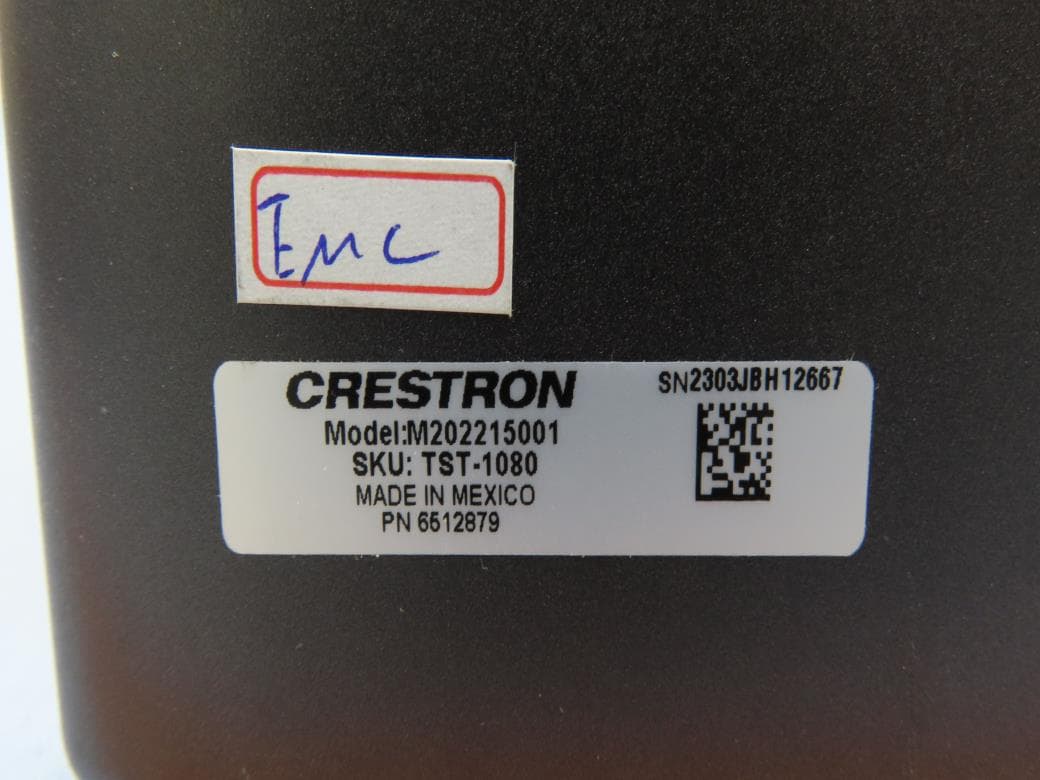
EROM202215001
Jul 05, 202310.1 in. Wireless Touch Screen
Equipment Class
DSS - Part 15 Spread Spectrum Transmitter
EROAM-TX3-200
Jan 13, 2023WIRELESS MEDIA TRANSMITTER
Equipment Class
NII - Unlicensed National Information Infrastructure TX
EROAM-TX3
Jun 06, 2021Wireless Media Transmitter
Equipment Class
DTS - Digital Transmission System