EROCWD7219Two-Way RF Transceiver Module
Crestron Electronics Inc
Click to zoom
Application Details
- Equipment Class
- DTS - Digital Transmission System
- Date of Grant
- Feb 14, 2013
- Application Purpose
- Original Equipment
- Date of Application
- Feb 14, 2013
- Equipment Note
- Two-Way RF Transceiver Module
- Frequency Range
- 2405.00000000 - 2480.00000000
- Company
- Crestron Electronics Inc
- Country
- United States
Documents & Files
Document Text
Text extracted from the exhibit documents filed with the FCC. Open a document above to read the original.
Users Manual
Crestron CWD7219 Two-Way RF Transceiver Module Operations Guide This document was written by the Technical Publications department at Crestron. ©2013 Crestron Electronics, Inc. Regulatory Compliance Federal Communications Commission (FCC) Compliance Statement CAUTION: Changes or modifications not expressly approved by the manufacturer responsible for compliance could void the user’s authority to operate the equipment. NOTE: This equipment has been tested and found to comply with the limits for a Class B digital device, pursuant to part 15 of the FCC Rules. These limits are designed to provide reasonable protection against harmful interference in a residential installation. This equipment generates, uses and can radiate radio frequency energy and, if not installed and used in accordance with the instructions, may cause harmful interference to radio communications. However, there is no guarantee that interference will not occur in a particular installation. If this equipment does cause harmful interference to radio or television reception, which can be determined by turning the equipment off and on, the user is encouraged to try to correct the interference by one or more of the following measures: Reorient or relocate the receiving antenna Increase the separation between the equipment and receiver Connect the equipment into an outlet on a circuit different from that to which the receiver is connected Consult the dealer or an experienced radio/TV technician for help Industry Canada (IC) Compliance Statement This device complies with Industry Canada license-exempt RSS standard(s). Operation is subject to the following two conditions: (1) this device may not cause interference and (2) this device must accept any interference, including interference that may cause undesired operation of the device. Under Industry Canada regulations, this radio transmitter may only operate using an antenna of a type and maximum (or lesser) gain approved for the transmitter by Industry Canada. To reduce potential radio interference to other users, the antenna type and its gain should be so chosen that the equivalent isotropically radiated power (e.i.r.p.) is not more than that necessary for successful communication. This radio transmitter, IC: 5683C-CWD7219, has been approved by Industry Canada to operate with the antenna types listed below with the maximum permissible gain and required antenna impedance for each antenna type indicated. Antenna types not included in this list, having a gain greater than the maximum gain indicated for that type, are strictly prohibited for use with this device. Antenna Type: Dipole, Maximum permissible antenna gain: 2.5 dBi, Impedance: 50 Ohms Industrie Canada (IC) Déclaration de conformité Le présent appareil est conforme aux CNR d'Industrie Canada applicables aux appareils radio exempts de licence. L'exploitation est autorisée aux deux conditions suivantes : (1) l'appareil ne doit pas produire de brouillage, et (2) l'utilisateur de l'appareil doit accepter tout brouillage radioélectrique subi, même si le brouillage est susceptible d'en compromettre le fonctionnement. Conformément à la réglementation d'Industrie Canada, le présent émetteur radio peut fonctionner avec une antenne d'un type et d'un gain maximal (ou inférieur) approuvé pour l'émetteur par Industrie Canada. Dans le but de réduire les risques de brouillage radioélectrique à l'intention des autres utilisateurs, il faut choisir le type d'antenne et son gain de sorte que la puissance isotrope rayonnée équivalente (p.i.r.e.) ne dépasse pas l'intensité nécessaire à l'établissement d'une communication satisfaisante. Le présent émetteur radio , IC: 5683C-CWD7219, a été approuvé par Industrie Canada pour fonctionner avec les types d'antenne énumérés ci-dessous et ayant un gain admissible maximal et l'impédance requise pour chaque type d'antenne. Les types d'antenne non inclus dans cette liste, ou dont le gain est supérieur au gain maximal indiqué, sont strictement interdits pour l'exploitation de l'émetteur. Type d'antenne: Dipole, Gain admissible maximal: 2.5 dBi, Impédance: 50 Ohms To satisfy RF exposure requirements, this device and its antenna must operate with a separation distance of at least 20 centimeters from all persons and must not be collocated or operating in conjunction with any other antenna or transmitter. Crestron CWD7219 Two-Way RF Transceiver Module Operations Guide - DOC. 7510A Contents i Contents Two-Way RF Transceiver Module: CWD7219 .............................................. 1 Functions and Features .............................................................................................................. 1 Specifications ............................................................................................................................. 2 Physical Description .................................................................................................................. 3 Ports ............................................................................................................................. 3 Power/I-O .................................................................................................................... 4 Labeling Requirements .............................................................................................................. 4 Documentation ........................................................................................................................... 4 Crestron CWD7219 Two-Way RF Transceiver Module Operations Guide - DOC. 7510A Two-Way RF Transceiver Module: CWD7219 1 2.4 GHz frequency band, IEEE 802.15.4 specification Range from 3 feet to 550 ft. Operates on one of sixteen available channels to establish optimal signal quality Two-Way RF Transceiver Module: CWD7219 Functions and Features The CWD7219 (hereafter referred to as “module”) with a dipole antenna, is a two-way radio frequency (RF) module that utilizes the 2.4…
Text truncated - open the document above for the full version.
Cover Letter(s)
Crestron Electronics, Inc. 22 Link Drive Rockleigh, NJ 07647 Tel: 800.237.2041/ 201.767.3400 Fax: 201.767.7576 www.crestron.com February 12, 2013 Federal Communications Commission 7435 Oakland Mills Road Columbia MD 21046 Subject: Request for Confidentiality FCC ID: EROCWD7219 To Whom It May Concern: Pursuant to the provisions of Sections 0.457 and 0.459 of the Commission’s rules (47 CFR §§ 0.457, 0.459), we are requesting the Commission to permanently withhold the following attachments as confidential document from public disclosure. Schematic Diagram Block Diagram Theory of Operation Above mentioned document contains detailed system and equipment description are considered as proprietary information in operation of the equipment. The public disclosure of above documents might be harmful to our company and would give competitor an unfair advantage in the market. It is our understanding that all measurement test reports, FCC ID label format and correspondent during certification review process cannot be granted as confidential documents and those information will be available for public review once the grant of equipment authorization is issued. Best Regards Crestron Electronics Inc. Grace Lin Sr. Compliance Engineer Email: [email protected] Telephone: 201-750-7004 extension 11464
Cover Letter(s)
Crestron Electronics, Inc. 22 Link Drive Rockleigh, NJ 07647 Tel: 800.237.2041/ 201.767.3400 Fax: 201.767.7576 www.crestron.com Transmitter Modular Approval Attestation Feb. 13, 2013 Subject: FCC ID: EROCWD7219, IC: 5683C-CWD7219 To Whom It May Concern: The following attestation addresses the requirements to support modular approval as required by the FCC and IC. Rule Sections Description FCC Part 15 IC RSS-Gen §15.212 (a) §7.1.1 (a) This module is a single modular transmitter consists of a completely self- contained RF transmitter device that is typically incorporated into another product, host, or device. §15.212 (a)(1)(i) §7.1.1 (b) The module has integral RF shielding to isolate it from surrounding equipment and the large environment in general. §15.212 (a)(1)(ii) §7.1.1 (c) All inputs are processed as data by the radio control element. The outside user has no direct control of transmit modulation. §15.212 (a)(1)(iii) §7.1.1 (d) The radio front end contains a linear regulator to regulate device operation over voltage variations and to limit the output power under high voltage conditions. §15.212 (a)(1)(iv) §7.1.1(e) This module is validated with a dipole antenna. The RP-SMA antenna connector is unique in the sense of complying with FCC §15.203, §15.204(b), and §15.204(c). §15.212 (a)(1)(v) §7.1.1 The module was tested in a stand-alone configuration. It complies with the AC line conducted requirements found in FCC §15.207 and IC RSS-Gen Table 2 requirements. §15.212 (a)(1)(vi) §5.2 An ID label is affixed to each unit at the time of manufacture. Information is also clearly presented in the user guide about labeling requirements for the final assembly. §15.212 (a)(1)(vii) §7.1.1 This module is compliant with FCC §15.247 and IC RSS-Gen/RSS-210 rules. Installation and other requirements are presented in the user guide to allow the unit to be correctly installed. §15.212 (a)(1)(viii) §5.5 This module is compliant with the RF exposure requirements of FCC Parts §15.247, §15.1091, §15.1093, and IC RSS-Gen §5.5. Please feel free to contact us with any additional questions or information. Best Regards Crestron Electronics Inc. Grace Lin Sr. Compliance Engineer Email: [email protected], Telephone: 201-750-7004 extension 11464
External Photos
FCC ID: EROCWD7219 IC: 5683C-CWD7219 External Photos Page 1 of 1 External Photos
ID Label/Location Info
FCC ID: EROCWD7219 IC: 5683C-CWD7219 ID Label Location Page 1 of 1 ID Label Location
ID Label/Location Info
REVISIONS NAMEREVDESCRIPTIONDATEAPPROVED RHAORIGINALISSUEPEREWO192211/16/12 22LINKDRIVE,ROCKLEIGH,N.J.07647 (201)750-7004FAX(201)767-5772 NAMEDATE DRAWNBY CHECKED FINISHEDGDS DESIGNEDBY SIZE PRINTNUMBER REV LABEL,CUSTOM,FCCID,CWD7219 POLYESTER,APX:.60X.30X.002 A274558 UNLESSOTHERWISESPECIFIED: ALLDIMENSIONSAREININCHES TOLERANCESARE: FRACTIONS1/64ANGLES½ DECIMALS.XX.01.XXX.005 ±±° ±± THISDRAWINGISTHEEXCLUSIVEPROPERTYOFCRESTRONELECTRONICS,INC.DISCLOSUREORREPRODUCTIONINWHOLE ORINPART,WITHOUTPRIORWRITTENPERMISSION,ISPROHIBITEDEXCEPTFORTHEMANUFACTUREOFARTICLESFORCRESTRON. USEDON SORTNAME 1:1 APPROVED DEBURR&BREAKALLSHARPEDGES RH11/16/12 RH 11/16/12 6506222 DIN-AP3EX 6506221DIN-AP3MEX SCALE:274558-A.CDRFILE:SHEET1OF1 A ALLPARTS&PROCESSESMUSTBE COMPLIANTRoHS IC:5683C-CWD7219 FCCID:EROCWD7219 MODEL:CWD7219 NOTES: 1.MATERIAL:WHITEPOLYESTER,.002”THKWITH PERMANENTADHESIVEBACKING. 2.PRINT:TEXTANDGRAPHICS-BLACK. 3.USEARTWORK26980-A,INONEOFITS ORIGINAL,AVAILABLEFORMATS(THE274558 DRAWINGISAREPRESENTATIONOFTHE ARTWORK,SEETHEACTUALARTWORKDRAWING FORTHECORRECTINFORMATION) 4.TOLERANCE+/-.010EXCEPTWHERENOTED OTHERWISE. 0.600 R.030
Internal Photos
FCC ID: EROCWD7219 IC: 5683C-CWD7219 Internal Photo Page 1 of 1 Internal Photo
RF Exposure Info
FCC ID: EROCWD7219 IC: 5683C-CWD7219 Page 1 of 1 Maximum Permissive Exposure Performance Criterion: The human RF exposure limit is 1 mW/cm 2 . Evaluation Results: Complies Details: The maximum permissible exposure (MPE) is predicted by using Equation (3) of Section 2 of FCC OET Bulletin 65, Edition 97-01: S = PG/4πR 2 where: S = power density (in appropriate units, e.g. mW/cm 2 ) P = power input to the antenna (in appropriate units, e.g., mW) G = power gain of the antenna in the direction of interest relative to an isotropic radiator R = distance to the center of radiation of the antenna (appropriate units, e.g., cm) P = 146.22 mW, G = 1.7783 (2.5 dBi), R = 20 cm S = 0.0517 mW/cm 2 = 0.517 W/m 2 MPE limit for uncontrolled exposure at prediction frequency: 1 mW/cm 2 Maximum allowable antenna gain: 15.36 dBi Margin of Compliance at 20 cm = 12.86 dB
Test Report
FCC ID: EROCWD7219 IC: 5683C-CWD7219 Page 1 of 32 Test Report FCC Part 15, Subpart C, Section 15.247 Industry Canada RSS-210, Issue 8 Report Number: CWD7219-Cert Model: CWD7219 FCC ID: EROCWD7219 IC: 5683C-CWD7219 Date: February 8, 2013 Prepared by: Grace Lin Date: Feb. 8, 2013 Grace Lin, Sr. Compliance Engineer Reviewed by: Wayne Owens Date: Feb. 8, 2013 Wayne Owens, Director of Program Management FCC ID: EROCWD7219 IC: 5683C-CWD7219 Page 2 of 32 Table of Contents 1. GENERAL DESCRIPTION ................................................................................................ 3 1.1 PRODUCT DESCRIPTION ................................................................................................... 3 1.2 TEST METHODOLOGY ...................................................................................................... 3 1.3 TEST FACILITY ................................................................................................................. 3 1.4 TEST EQUIPMENT ............................................................................................................. 4 1.5 EVALUATION SUMMARY .................................................................................................. 4 2. SYSTEM TEST CONFIGURATION ................................................................................. 5 2.1 JUSTIFICATION ................................................................................................................. 5 2.2 BLOCK DIAGRAM ............................................................................................................. 5 2.3 EUT EXERCISE SOFTWARE AND MODE(S) OF OPERATION ............................................... 5 2.4 CABLES ............................................................................................................................ 5 2.5 SPECIAL ACCESSORIES ..................................................................................................... 6 2.6 SUPPORT EQUIPMENT ....................................................................................................... 6 2.7 EQUIPMENT MODIFICATIONS ........................................................................................... 6 3. EVALUATION ..................................................................................................................... 7 3.1 ANTENNA REQUIREMENTS ............................................................................................... 7 3.2 6 DB BANDWIDTH ............................................................................................................ 8 3.3 99% BANDWIDTH .......................................................................................................... 11 3.4 POWER OUTPUT ............................................................................................................. 13 3.5 BAND EDGE ................................................................................................................... 16 3.6 CONDUCTED SPURIOUS EMISSIONS ................................................................................ 18 3.7 POWER SPECTRAL DENSITY ........................................................................................... 22 3.8 RADIATED SPURIOUS EMISSIONS ................................................................................... 25 3.9 RECEIVER RADIATED EMISSIONS ................................................................................... 28 3.10 RECEIVER AC POWER LINE CONDUCTED EMISSIONS .................................................... 31 FCC ID: EROCWD7219 IC: 5683C-CWD7219 Page 3 of 32 1. General Description 1.1 Product Description The equipment under test (EUT) is a Crestron 2.4GHz two-way RF transceiver module, model: CWD7219. 1.2 Test Methodology Measurements were performed according to the following procedures and standards: 1) ANSI C63.4: 2009 2) FCC Publication, “Guidance for Performing Compliance Measurements on Digital Transmission Systems (DTS) Operating under §15.247”, October 4, 2012 3) Industry Canada RSS-Gen Issue 3 4) Industry Canada RSS-210 Issue 8 5) Industry Canada ICES-003 Issue 5 All measurements were performed in a 3-meter semi-anechoic chamber and the control room. 1.3 Test Facility The 3-meter semi-anechoic chamber used to collect conducted and radiated emission data is located at 22 Link Drive, Rockleigh, New Jersey. This test facility has been placed on file with the FCC, Registration Number: 412871, and Industry Canada, Site Number: 5683C-1. FCC ID: EROCWD7219 IC: 5683C-CWD7219 Page 4 of 32 1.4 Test Equipment Description Model Serial No. Frequency Range Calibration Date R&S EMI Receiver ESU40 100076 20 Hz – 40 GHz Dec. 13, 2012 Teseq Bilog Antenna CBL 6112D 25231 30 MHz – 2 GHz Dec. 11, 2012 ETS-Lindgren Double Ridge Horn Antenna 3117 00047560 1 GHz – 18 GHz Feb. 23, 2013 R&S Preamplifier TS-PR18 100044 30 MHz – 18 GHz Dec. 11, 2012 ETS-Lindgren Standard Gain Horn Antenna 3160-09 00078911 18 GHz – 26.5 GHz Feb. 5, 2013* R&S Preamplifier TS-PR26 100030 18 GHz – 26.5 GHz Dec. 11, 2012 Solar Electronics LISN 9252-50-R-24-N 068545 10 kHz – 50 MHz Mar. 5, 2012 *Mechanical inspection 1.5 Evaluation Summary Rule Section Description/Parameters Results FCC IC §15.203 N/A Antenna Requirement Complies §15.247(a)(2) §A8.2(a) of RSS-210 6 dB Bandwidth, 500 kHz Complies N/A §4.6.1 of RSS-Gen 99% Occupied Bandwidth (for reporting purpose) §15.247(b)(3) §A8.4(4) of RSS-210 Power Output, conducted, 1 Watt (30dBm) Complies §15.247(d) §2.1, §A8.5 of RSS- 210 Band Edge Complies §15.247(d) §A8.5 of RSS-210 Conducted Spurious Emissions, 20 dBc Complies §15.247(e) §A8.2(b) of RSS-210 Power Spectral Density (PSD), 8 dBm in any 3 kHz band. Complies §15.205, §15.209, §15.247(d) §2.2, §2.7, §A8.5 of RSS-210 Radiated Spurious Emissions Complies §15.101(b) §6 of RSS-Gen Receiver Radiated Emission Complies §15.107 §7.2.2 of RSS-Gen Receiver AC Power Line Conducted Emissions Complies Note: The channels selecte…
Text truncated - open the document above for the full version.
Test Setup Photos
FCC ID: EROCWD7219 IC: 5683C-CWD7219 Test Setup Photos Page 1 of 2 Test Setup Photos Conducted Emission Configuration Photographs Worst-case conducted emission, front view Worst-case conducted emission, side view FCC ID: EROCWD7219 IC: 5683C-CWD7219 Test Setup Photos Page 2 of 2 Test Setup Photos Radiated Emission Configuration Photographs Worst-case radiated emission, front view Worst-case radiated emission, rear view
Contact Information
Applicant
Chirag Patel(Lead Compliance Engineer)
Test Firm
Crestron Electronics, Inc.Mairaj Hussain
[email protected]201-750-7004
Technical Specifications
| # | Rule Parts | Frequency Range | Power Output |
|---|---|---|---|
| 1 | 15C | 2.40 GHz - 2.48 GHz | 146.22 mW |
Other Applications from Crestron Electronics Inc
EROTSW1580
Jan 29, 202615 inch Touch Screen wall mount
Equipment Class
6XD - 15E 6 GHz Low Power Indoor Client
EROM202108007
Sep 19, 2023Crestron Video Bar with WIFI and Bluetooth
Equipment Class
NII - Unlicensed National Information Infrastructure TX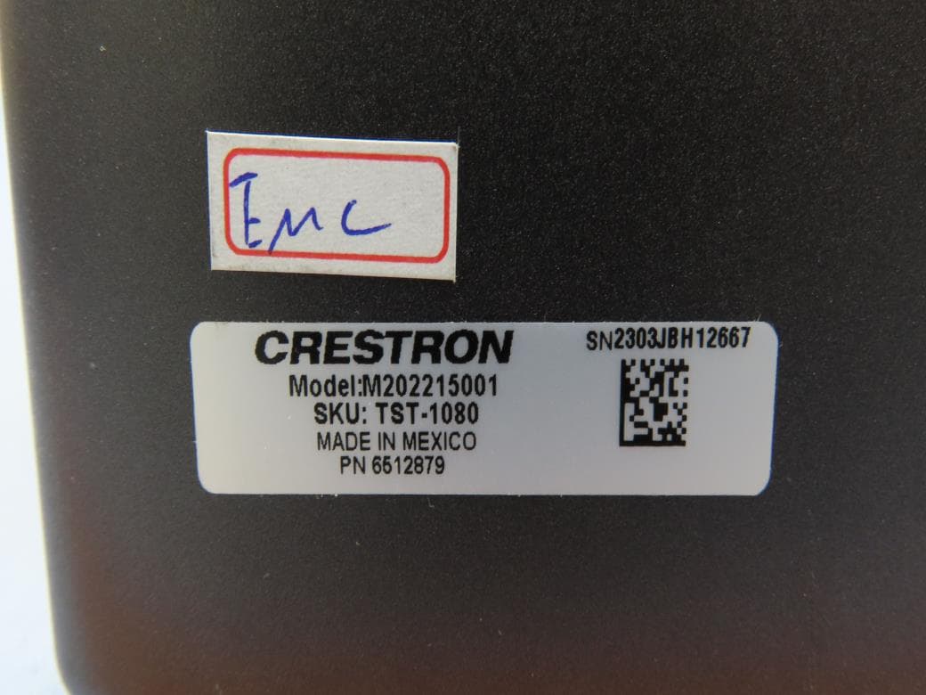
EROM202215001
Jul 05, 202310.1 in. Wireless Touch Screen
Equipment Class
DSS - Part 15 Spread Spectrum Transmitter
EROAM-TX3-200
Jan 13, 2023WIRELESS MEDIA TRANSMITTER
Equipment Class
NII - Unlicensed National Information Infrastructure TX
EROAM-TX3
Jun 06, 2021Wireless Media Transmitter
Equipment Class
DTS - Digital Transmission System