EROHTT-B2EXBattery-Powered InfiNET EX 2-Button Wireless Keypad
Crestron Electronics Inc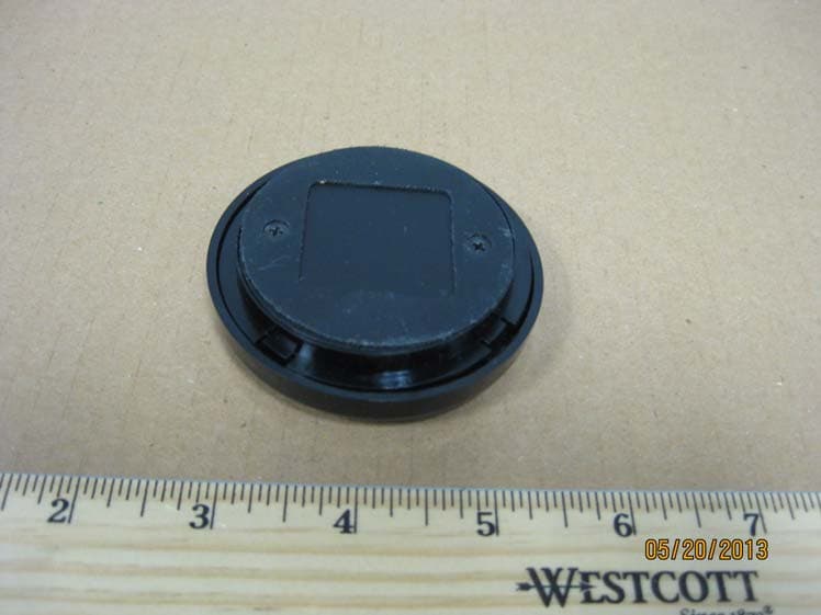
Click to zoom
Application Details
- Equipment Class
- DTS - Digital Transmission System
- Date of Grant
- Jun 04, 2013
- Application Purpose
- Original Equipment
- Date of Application
- Jun 04, 2013
- Equipment Note
- Battery-Powered InfiNET EX 2-Button Wireless Keypad
- Frequency Range
- 2405.00000000 - 2480.00000000
- Company
- Crestron Electronics Inc
- Country
- United States
Documents & Files
Document Text
Text extracted from the exhibit documents filed with the FCC. Open a document above to read the original.
Users Manual
HTT-B2EX-BATT Regulatory Compliance Federal Communications Commission (FCC) Compliance Statement This device complies with part 15 of the FCC Rules. Operation is subject to the following conditions: (1) This device may not cause harmful interference and (2) this device must accept any interference received, including interference that may cause undesired operation. CAUTION: Changes or modifications not expressly approved by the manufacturer responsible for compliance could void the user’s authority to operate the equipment. NOTE: This equipment has been tested and found to comply with the limits for a Class B digital device, pursuant to part 15 of the FCC Rules. These limits are designed to provide reasonable protection against harmful interference in a residential installation. This equipment generates, uses and can radiate radio frequency energy and, if not installed and used in accordance with the instructions, may cause harmful interference to radio communications. However, there is no guarantee that interference will not occur in a particular installation. If this equipment does cause harmful interference to radio or television reception, which can be determined by turning the equipment off and on, the user is encouraged to try to correct the interference by one or more of the following measures: Reorient or relocate the receiving antenna Increase the separation between the equipment and receiver Connect the equipment into an outlet on a circuit different from that to which the receiver is connected Consult the dealer or an experienced radio/TV technician for help Industry Canada (IC) Compliance Statement This device complies with Industry Canada licence-exempt RSS standard(s). Operation is subject to the following two conditions: (1) this device may not cause interference, and (2) this device must accept any interference, including interference that may cause undesired operation of the device. Under Industry Canada regulations, this radio transmitter may only operate using an antenna of a type and maximum (or lesser) gain approved for the transmitter by Industry Canada. To reduce potential radio interference to other users, the antenna type and its gain should be so chosen that the equivalent isotropically radiated power (e.i.r.p.) is not more than that necessary for successful communication. Industrie Canada (IC) Déclaration de conformité Le présent appareil est conforme aux CNR d'Industrie Canada applicables aux appareils radio exempts de licence. L'exploitation est autorisée aux deux conditions suivantes : (1) l'appareil ne doit pas produire de brouillage, et (2) l'utilisateur de l'appareil doit accepter tout brouillage radioélectrique subi, même si le brouillage est susceptible d'en compromettre le fonctionnement. Conformément à la réglementation d'Industrie Canada, le présent émetteur radio peut fonctionner avec une antenne d'un type et d'un gain maximal (ou inférieur) approuvé pour l'émetteur par Industrie Canada. Dans le but de réduire les risques de brouillage radioélectrique à l'intention des autres utilisateurs, il faut choisir le type d'antenne et son gain de sorte que la puissance isotrope rayonnée équivalente (p.i.r.e.) ne dépasse pas l'intensité nécessaire à l'établissement d'une communication satisfaisante. Crestron Electronics, Inc. 15 Volvo Drive, Rockleigh, NJ 07647 Tel: 888.CRESTRON Fax: 201.767.7576 www.crestron.com DOC. 7451 (2036668) 05.13 Specifications subject to change without notice. Return and Warranty Policies Merchandise Returns / Repair Service 1. No merchandise may be returned for credit, exchange or service without prior authorization from Crestron. To obtain warranty service for Crestron products, contact an authorized Crestron dealer. Only authorized Crestron dealers may contact the factory and request an RMA (Return Merchandise Authorization) number. Enclose a note specifying the nature of the problem, name and phone number of contact person, RMA number and return address. 2. Products may be returned for credit, exchange or service with a Crestron Return Merchandise Authorization (RMA) number. Authorized returns must be shipped freight prepaid to Crestron, 6 Volvo Drive, Rockleigh, N.J. or its authorized subsidiaries, with RMA number clearly marked on the outside of all cartons. Shipments arriving freight collect or without an RMA number shall be subject to refusal. Crestron reserves the right in its sole and absolute discretion to charge a 15% restocking fee plus shipping costs on any products returned with an RMA. 3. Return freight charges following repair of items under warranty shall be paid by Crestron, shipping by standard ground carrier. In the event repairs are found to be non-warranty, return freight costs shall be paid by the purchaser. Crestron Limited Warranty Crestron Electronics, Inc. warrants its products to be free from manufacturing defects in materials and workmanship under normal use for a period of three (3) years from the date of purchase from Crestron, with the following exceptions: disk drives and any other moving or rotating mechanical parts, pan/tilt heads and power supplies are covered for a period of one (1) year; touch screen display and overlay components are covered for 90 days; batteries and incandescent lamps are not covered. This warranty extends to products purchased directly from Crestron or an authorized Crestron dealer. Purchasers should inquire of the dealer regarding the nature and extent of the dealer's warranty, if any. Crestron shall not be liable to honor the terms of this warranty if the product has been used in any application other than that for which it was intended or if it has been subjected to misuse, accidental damage, modification or improper installation procedures. Furthermore, this warranty does not cover any product that has had the serial number altered, defaced or removed. This warranty shall be the sole and exclusive remedy to the original purchaser. In no event shall Crestron be liable fo…
Text truncated - open the document above for the full version.
Users Manual
1 quickstart guide HTT-B2EX-BATT www.crestron.com 888.273.7876201.767.3400 Specifications subject to change without notice. HTT-B2EX-BATT For Regulatory Compliance information, refer to the latest version of Doc. 7451. QUICKSTART DOC. 7450 (2036667) 05.13 Battery-Powered infiNET EX 2-Button Wireless Keypad 1 The HTT-B2EX-BATT is a battery-powered, 2-button, wireless keypad designed to control a wide range of applications supported by a Crestron ® control system. Compact and simplistic in design, the HTT-B2EX-BATT is an ideal tabletop keypad for use as a hotel bedside controller, a conference room presenter selector or a simple living room lighting/shade controller. The HTT-B2EX-BATT is powered by lithium coin cell batteries that boast high performance and a long battery life. Outfitted with Crestron infiNET EX ® technology, the HTT-B2EX-BATT can be wirelessly connected to a Crestron control system. The HTT-B2EX-BATT is available with an optional tether that allows the device to be secured at its mounting location. infiNET EX Communication Built on steadfast infiNET™ technology, infiNET EX is the new standard in 2-way wireless connectivity that can handle installations in even the most urban settings. The redundant nature of its mesh networking technology means that a command will never be missed, resulting in faultless operation—something that is of the utmost importance when it comes to home automation. The HTT-B2EX-BATT harnesses this cutting edge wireless connectivity which affords it a level of robustness and dependability above other solutions. Description Installation of the HTT-B2EX-BATT is limited to powering the device, placing it on a flat surface and securing it to the line cord of a lamp (optional). Power Device The HTT-B2EX-BATT is shipped with the batteries pre-installed. To power the device pull and remove the plastic tab on the side of the device. Once the plastic tab is removed the device is powered and ready to be operated. Properly discard the plastic tab. Place Device Place the HTT-B2EX-BATT on the table surface where it is to be used. Secure Device (Optional) A security tether is available on the HTT-B2EX-BATT-B-T W/TETHER and HTT-B2EX-BATT-W-T W/TETHER. The tether is secured inside the cover of the keypad and attaches to a lamp cord. Use the following steps to secure the loose end of the tether to a lamp cord. 1. Wrap the loose end of the tether around the lamp cord. The loop should be loose enough to allow the tether to slide along the lamp cord but not loose enough to slide it over the plug. 2. Use the supplied metal crimp and a pair of pliers to secure the tether to the lamp cord. 3. Neatly trim the excess wire from the tether using a pair of wire cutters. 2 Installation 4 Firmware It is recommended to use Crestron Toolbox™ to set the RF ID of the device while the device is awake. Wake the device by pressing the large or small button on the HTT-B2EX-BATT. The RF ID of the unit, set using Crestron Toolbox, must match the RF ID specified in the Crestron Studio™ or SIMPL Windows program. 3 RF ID The device connects to the Crestron network via the infiNET EX communications protocol. Use the procedures outlined below to join or leave an infiNET EX network and to verify communications between the device and the control system. Joining an infiNET EX Network Before a device can be used in a lighting system, it must first join an infiNET EX network by being acquired by an infiNET EX gateway. NOTE: A device can be acquired by only one gateway. 1. Put the infiNET EX gateway into Acquire mode from the unit itself or from Crestron Toolbox, as described in the latest version of its manual, which is available from the Crestron Web site (www.crestron.com/manuals). NOTE: In an environment where multiple gateways are installed, only one gateway should be in Acquire mode at any time. (Continued on the following page) 5 Wireless Communication Lamp Cord Tether Metal Crimp 13/16 in (21 mm) Ø2 23/32 in (69 mm) Small Button Small Button LED Large Button Large Button LED To upgrade the firmware on the HTT-B2EX-BATT use Crestron Toolbox (v. 2.37.01 or later). Upload firmware with the infiNET EX Firmware Upload tool by clicking Tools | infiNET EX Firmware Upload in Crestron Toolbox. NOTE: This infiNET EX Firmware Upload tool eliminates the need for the user to manually wake every sensor that is being updated. NOTE: When using the infiNET EX Firmware Upload tool, the device does not update immediately. It updates upon waking up and communicating with the gateway. The infiNET EX Firmware Upload tool has four columns: product ID, Firmware image, model name, and version number. Assign the selected firmware image from the bottom box to the corresponding ID/model name. After pressing the load firmware file button, the gateway holds the file and waits for the device to wake up on its own. Once the device wakes up it checks for differences in the firmware file, if different than the one currently on the device the firmware is loaded onto the sensor. 2 quickstart guide HTT-B2EX-BATT www.crestron.com 888.273.7876201.767.3400 Specifications subject to change without notice. HTT-B2EX-BATT For Regulatory Compliance information, refer to the latest version of Doc. 7451. QUICKSTART DOC. 7450 (2036667) 05.13 Battery-Powered infiNET EX 2-Button Wireless Keypad WARNING: Refer to the following warnings before changing the batteries. • Do not ingest batteries, chemical burn hazard. • This product contains coin cell batteries. If a coin cell battery is swallowed, it can cause severe internal burns in just 2 hours and can lead to death. • Keep new and used batteries away from children. If the battery compartment does not close securely, stop using the product and keep it away from children. • If you think batteries have been swallowed or placed inside any part of the body, seek immediate medical attention. CAUTION: The battery used in this device may present a risk of fire or chemical burn if mistreated. Do not…
Text truncated - open the document above for the full version.
Cover Letter(s)
Crestron Electronics, Inc. 22 Link Drive Rockleigh, NJ 07647 Tel: 800.237.2041/ 201.767.3400 Fax: 201.767.7576 www.crestron.com May 31, 2013 Federal Communications Commission 7435 Oakland Mills Road Columbia MD 21046 Subject: Request for Confidentiality FCC ID: EROHTT-B2EX To Whom It May Concern: Pursuant to the provisions of Sections 0.457 and 0.459 of the Commission’s rules (47 CFR §§ 0.457, 0.459), we are requesting the Commission to permanently withhold the following attachments as confidential document from public disclosure. Schematic Diagram Block Diagram Theory of Operation Above mentioned document contains detailed system and equipment description are considered as proprietary information in operation of the equipment. The public disclosure of above documents might be harmful to our company and would give competitor an unfair advantage in the market. It is our understanding that all measurement test reports, FCC ID label format and correspondent during certification review process cannot be granted as confidential documents and those information will be available for public review once the grant of equipment authorization is issued. Best Regards Crestron Electronics Inc. Grace Lin Sr. Compliance Engineer Email: [email protected] Telephone: 201-750-7004 extension 11464
External Photos
FCC ID: EROHTT-B2EX IC: 5683C-HTTB2EX External Photos Page 1 of 1 External Photos
ID Label/Location Info
FCC ID: EROHTT-B2EX IC: 5683C-HTTB2EX ID Label Location Page 1 of 1 ID Label Location
Internal Photos
FCC ID: EROHTT-B2EX IC: 5683C-HTTB2EX Internal Photo Page 1 of 3 Internal Photos FCC ID: EROHTT-B2EX IC: 5683C-HTTB2EX Internal Photo Page 2 of 3 Internal Photo FCC ID: EROHTT-B2EX IC: 5683C-HTTB2EX Internal Photo Page 3 of 3 Internal Photo
RF Exposure Info
FCC ID: EROHTT-B2EX IC: 5683C-HTTB2EX Page 1 of 1 Maximum Permissive Exposure Performance Criterion: The human RF exposure limit is 1 mW/cm 2 . Evaluation Results: Complies Details: The maximum permissible exposure (MPE) is predicted by using Equation (3) of Section 2 of FCC OET Bulletin 65, Edition 97-01: S = PG/4πR 2 where: S = power density (in appropriate units, e.g. mW/cm 2 ) P = power input to the antenna (in appropriate units, e.g., mW) G = power gain of the antenna in the direction of interest relative to an isotropic radiator R = distance to the center of radiation of the antenna (appropriate units, e.g., cm) P = 5.2481 mW, G = 1.5488 (1.9 dBi), R = 20 cm S = 0.0016 mW/cm 2 = 0.016 W/m 2 MPE limit for uncontrolled exposure at prediction frequency: 1 mW/cm 2 Maximum allowable antenna gain: 29.8 dBi Margin of Compliance at 20 cm = 27.9 dB
Test Report
FCC ID: EROHTT-B2EX IC: 5683C-HTTB2EX Page 1 of 26 Test Report FCC Part 15, Subpart C, Section 15.247 Industry Canada RSS-210, Issue 8 Report Number: HTT-B2EX-BATT-Cert Model: HTT-B2EX-BATT FCC ID: EROHTT-B2EX IC: 5683C-HTTB2EX Date: June 4, 2013 Prepared by: Grace Lin Date: June 4, 2013 Grace Lin, Sr. Compliance Engineer Reviewed by: Wayne Owens Date: June 4, 2013 Wayne Owens, Director of Program Management FCC ID: EROHTT-B2EX IC: 5683C-HTTB2EX Page 2 of 26 Table of Contents 1. GENERAL DESCRIPTION ................................................................................................ 3 1.1 PRODUCT DESCRIPTION ................................................................................................... 3 1.2 TEST METHODOLOGY ...................................................................................................... 3 1.3 TEST FACILITY ................................................................................................................. 3 1.4 TEST EQUIPMENT ............................................................................................................. 4 1.5 EVALUATION SUMMARY .................................................................................................. 4 2. SYSTEM TEST CONFIGURATION ................................................................................. 5 2.1 JUSTIFICATION ................................................................................................................. 5 2.2 BLOCK DIAGRAM ............................................................................................................. 5 2.3 EUT EXERCISE SOFTWARE AND MODE(S) OF OPERATION ............................................... 5 2.4 CABLES ............................................................................................................................ 5 2.5 SPECIAL ACCESSORIES ..................................................................................................... 6 2.6 SUPPORT EQUIPMENT ....................................................................................................... 6 2.7 EQUIPMENT MODIFICATIONS ........................................................................................... 6 3. EVALUATION ..................................................................................................................... 7 3.1 ANTENNA REQUIREMENTS ............................................................................................... 7 3.2 DTS BANDWIDTH ............................................................................................................ 8 3.3 99% BANDWIDTH .......................................................................................................... 11 3.4 POWER OUTPUT ............................................................................................................. 13 3.5 BAND EDGE ................................................................................................................... 16 3.6 CONDUCTED SPURIOUS EMISSIONS ................................................................................ 18 3.7 POWER SPECTRAL DENSITY ........................................................................................... 22 3.8 RADIATED SPURIOUS EMISSIONS ................................................................................... 25 FCC ID: EROHTT-B2EX IC: 5683C-HTTB2EX Page 3 of 26 1. General Description 1.1 Product Description The equipment under test (EUT) is a Crestron Battery-Powered infiNET EX 2-Button Wireless Keypad operating at 2.4 GHz frequency band, model: HTT-B2EX-BATT, serial number: CNA 8113463. 1.2 Test Methodology Measurements were performed according to the following procedures and standards: 1) ANSI C63.4-2003 2) FCC Publication, “Guidance for Performing Compliance Measurements on Digital Transmission Systems (DTS) Operating under §15.247”, April 9, 2013 3) Industry Canada RSS-Gen Issue 3 4) Industry Canada RSS-210 Issue 8 All measurements were performed in a 3-meter semi-anechoic chamber and the control room. 1.3 Test Facility The 3-meter semi-anechoic chamber used to collect conducted and radiated emission data is located at 22 Link Drive, Rockleigh, New Jersey. This test facility has been placed on file with the FCC, Registration Number: 412871, and Industry Canada, Site Number: 5683C-1. FCC ID: EROHTT-B2EX IC: 5683C-HTTB2EX Page 4 of 26 1.4 Test Equipment Description Model Serial No. Frequency Range Calibration Date R&S EMI Receiver ESU40 100076 20 Hz – 40 GHz Dec. 13, 2012 Teseq Bilog Antenna CBL 6112D 25231 30 MHz – 2 GHz Dec. 11, 2012 ETS-Lindgren Double Ridge Horn Antenna 3117 00047560 1 GHz – 18 GHz Feb. 23, 2013 R&S Preamplifier TS-PR18 100044 30 MHz – 18 GHz Dec. 11, 2012 ETS-Lindgren Standard Gain Horn Antenna 3160-09 00078911 18 GHz – 26.5 GHz Feb. 5, 2013* R&S Preamplifier TS-PR26 100030 18 GHz – 26.5 GHz Dec. 11, 2012 *Mechanical inspection 1.5 Evaluation Summary Rule Section Description/Parameters Results FCC IC §15.203 N/A Antenna Requirement Complies §15.247(a)(2) §A8.2(a) of RSS-210 DTS Bandwidth, 500 kHz Complies N/A §4.6.1 of RSS-Gen 99% Occupied Bandwidth (for reporting purpose) §15.247(b)(3) §A8.4(4) of RSS-210 Power Output, conducted, 1 Watt (30dBm) Complies §15.247(d) §2.1, §A8.5 of RSS- 210 Band Edge Complies §15.247(d) §A8.5 of RSS-210 Conducted Spurious Emissions, 20 dBc Complies §15.247(e) §A8.2(b) of RSS-210 Power Spectral Density (PSD), 8 dBm in any 3 kHz band. Complies §15.205, §15.209, §15.247(d) §2.2, §A8.5 of RSS- 210 Radiated Spurious Emissions Complies §15.207 §7.2.4 of RSS-Gen Transmitter AC Power Line Conducted Emissions Complies Note: The channels selected for test were 11, 18, and 26. FCC ID: EROHTT-B2EX IC: 5683C-HTTB2EX Page 5 of 26 2. System Test Configuration 2.1 Justification In order for a DC power supply to supply power to the EUT and to access the test port, plastic enclosure was removed during measurement. A computer supplied test commands to…
Text truncated - open the document above for the full version.
Test Setup Photos
FCC ID: EROHTT-B2EX IC: 5683C-HTTB2EX Test Setup Photos Page 1 of 1 Test Setup Photos Radiated Emission Configuration Photographs Worst-case Front view Worst-case Rear view
Contact Information
Applicant
Chirag Patel(Lead Compliance Engineer)
Test Firm
Crestron Electronics, Inc.Mairaj Hussain
[email protected]201-750-7004
Technical Specifications
| # | Rule Parts | Frequency Range | Power Output |
|---|---|---|---|
| 1 | 15C | 2.40 GHz - 2.48 GHz | 5.25 mW |
Other Applications from Crestron Electronics Inc
EROTSW1580
Jan 29, 202615 inch Touch Screen wall mount
Equipment Class
6XD - 15E 6 GHz Low Power Indoor Client
EROM202108007
Sep 19, 2023Crestron Video Bar with WIFI and Bluetooth
Equipment Class
NII - Unlicensed National Information Infrastructure TX
EROM202215001
Jul 05, 202310.1 in. Wireless Touch Screen
Equipment Class
DSS - Part 15 Spread Spectrum Transmitter
EROAM-TX3-200
Jan 13, 2023WIRELESS MEDIA TRANSMITTER
Equipment Class
NII - Unlicensed National Information Infrastructure TX
EROAM-TX3
Jun 06, 2021Wireless Media Transmitter
Equipment Class
DTS - Digital Transmission System