EROQMTDC163Digital Shade Motor
Crestron Electronics Inc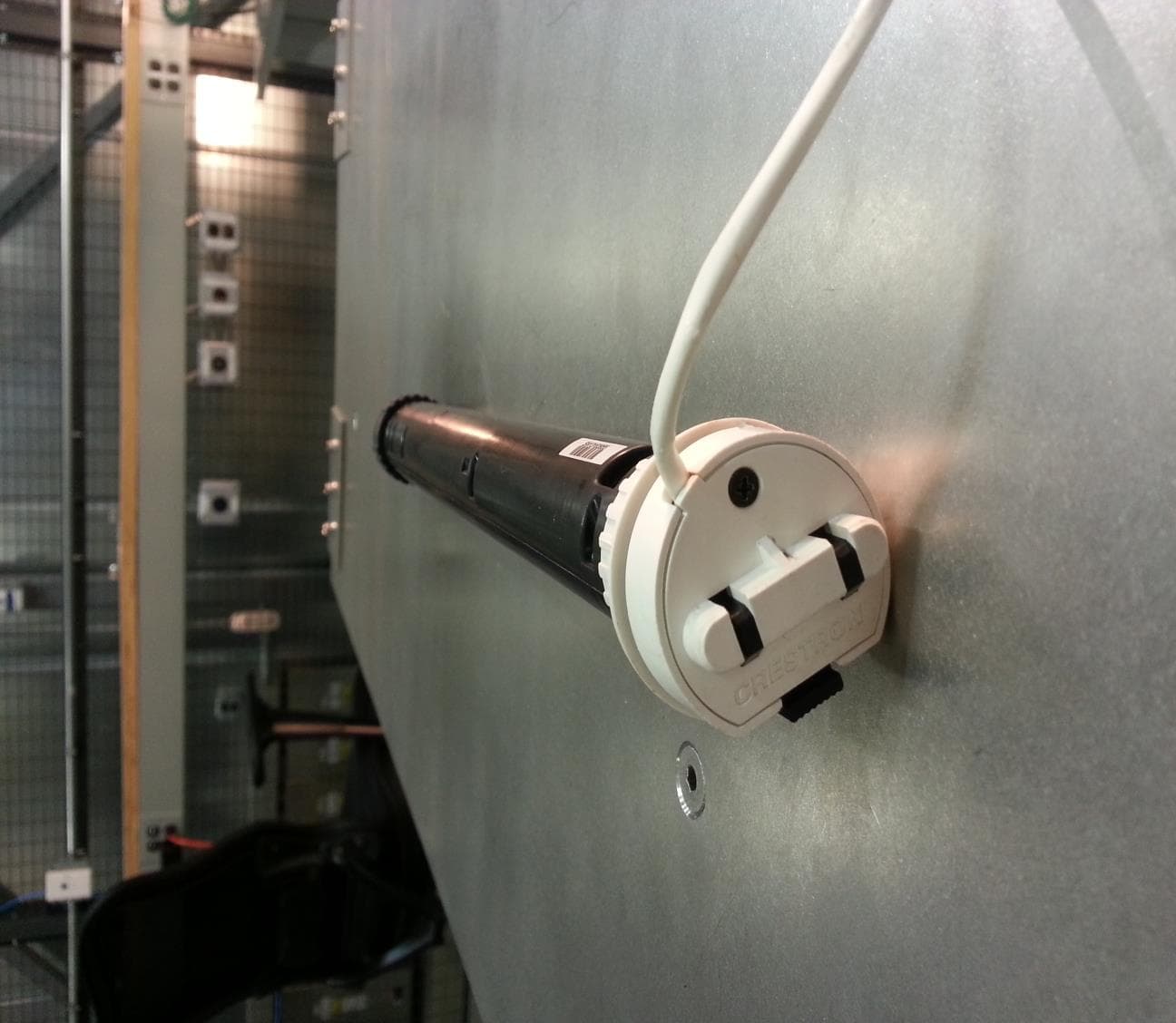
Click to zoom
Application Details
- Equipment Class
- DTS - Digital Transmission System
- Date of Grant
- Aug 03, 2015
- Application Purpose
- Original Equipment
- Date of Application
- Aug 03, 2015
- Equipment Note
- Digital Shade Motor
- Frequency Range
- 2405.00000000 - 2480.00000000
- Company
- Crestron Electronics Inc
- Country
- United States
Documents & Files
Document Text
Text extracted from the exhibit documents filed with the FCC. Open a document above to read the original.
Users Manual
CSM-QMTDC Digital QMT ® Shade Motor Programming Guide Controls and Indicators The Crestron CSM-QMTDC shade motors have labeled UP, SET, and DN push buttons that are used to program the shade. The motors have a multicolor LED that lights red, amber, green, blue, or white to provide con rmation, operating mode, and error state feedback. The UP button is located closest to the LED, the SET button is the second button from the LED, and the DN (down) button is the third button from the LED. Refer to the illustration below for details. Crestron CSM-QMTDC Motor Multicolor LED and Push Button Orientation Test the Shade Before the shade is operated, the motor must be tested to ensure that the motor direction is correct and that the shade travels correctly while raising and lowering. WARNING: Care has been taken to ensure that your shade is properly balanced. Prior to initial operation, please con rm that your brackets have been adjusted so that the shade hangs level and plumb. Upon startup, run the shade all the way down and check for plumb. Observe the shade closely as it rolls up. If the shade begins to telescope, stop immediately and take the appropriate action to ensure the shade tracks properly. To prevent damage to the fabric from telescoping, you should not leave the shade unattended during the rst few cycles of operation. Failure to follow these instructions may result in damage to the edge of the fabric, which is not covered by the warranty. Test Motor Direction Press the DN (down) button to lower the shade. If the shade begins to travel up, the motor direction must be reversed. To reverse the shade direction, press and hold the SET button for 10 seconds. The red LED lights for 3 seconds. NOTE: Reversing the direction of the motor resets any limits that have been previously set. After setting either the upper or lower limit, the motor automatically enters Limit Setup mode for the opposite limit. Follow the procedure in "Set Shade Limits" to reassign limits. Test Shade Travel Using the DN and UP buttons, ensure that the shade travels to the anticipated lower limit and then back to the expected upper limit. The shade should not come in contact with any building materials. The shade should travel the full length of the window opening and stop before reaching the top or bottom of the window opening. If the shade does not travel as expected, refer to "Set Up the Shade" below. Set Up the Shade Test Shade Limits Shade limits are set from the factory, but it may be necessary to reset them depending on the installation conditions. Test the lower limits by lowering the shade until it reaches its lower limit. Test the upper limits by raising the shade until it reaches its upper limit. Refer to “Set Shade Limits” if the limits need to change. Set Shade Limits When the shade limits are not set, the red LED blinks three times, pauses for 1 second, blinks once, pauses for 5 seconds, and then repeats this code until the limits are set. NOTE: After 8 seconds of inactivity, Limit Setup mode is exited. Set the lower limit for the shade. 1. Press and hold SET for 4 seconds to enter Limit Setup mode. The LED alternates between amber and green. 2. Press and release the DN button to begin lower limit setup. The green LED blinks. 3. Use the UP and DN buttons to set the shade to its desired position. 4. Press and hold SET for 4 seconds. The LED turns solid red to con rm that the lower limit was successfully set. NOTE: If the upper limit is not set when the lower limit is saved, the motor automatically enters upper limit mode upon saving the lower limit. This typically occurs when the motor direction has been reversed and both limits are erased. Set the upper limit for the shade. 1. Press and hold SET for 4 seconds to enter Limit Setup mode. The LED alternates between amber and green. 2. Press and release the UP button to begin upper limit setup. The amber LED blinks. 3. Use the UP and DN buttons to set the shade to its desired position. 4. Press and hold SET for 4 seconds. The LED turns solid red to confirm that the upper limit was successfully set. NOTE: If the lower limit is not set when the upper limit is saved, the motor switches to allow setting the lower limit after saving the upper limit. This typically occurs when the motor direction has been reversed and both limits are erased. Joining an in NET EX Network (in NET EX Interfaces Only) The device connects to the Crestron network via the in NET EX ® communications protocol. Use the procedures outlined below to join or leave an in NET EX network and to verify communications between the device and the control system. Joining an in NET EX Network Before a device can be used in a shading system, it must rst join an in NET EX network by being acquired by an in NET EX gateway. NOTE: A device can be acquired by only one gateway. 1. Put the in NET EX gateway into Acquire mode from the unit itself or from Crestron Toolbox™, as described in its manual at www.crestron.com/manuals. NOTE: In an environment where multiple gateways are installed, only one gateway should be in the Acquire mode at any time. 2. Place the device into Acquire mode. a. Tap the SET button three times, then press and hold it down (tap-tap-tap-press+hold) until the white LED starts to blink (this can take up to 10 seconds). b. When the white LED blinks, release the button to start the acquire process. • The interface is acquired when the LED stops blinking. • If the acquire process fails, the LED blinks rapidly until a button is pressed. 3. Once all devices have been acquired, take the gateway out of Acquire mode. Refer to the gateways’ operations guide for more information To leave an in NET EX network, put the device into Acquire mode, as described in “Joining an in NET EX Network” above, when no gateway is in Acquire mode. Verifying Communications Status To check the communications status of the device, tap the SET button three times and then press and hold it down (tap-tap-tap-press+hold) f…
Text truncated - open the document above for the full version.
External Photos
FCC ID: EROQMTDC163 IC: 5683C-QMTDC163 External photo: FCC ID: EROQMTDC163 IC: 5683C-QMTDC163 FCC ID: EROQMTDC163 IC: 5683C-QMTDC163
ID Label/Location Info
NOTES: ( 1. MATERIAL: UL/CSA APPROVED GLOSS COATED SILVER POLYESTER, .002” THK WITH PERMANENT ACRYLIC ADHESIVE. 2. PRINT: TEXT AND GRAPHICS - BLACK. 3. USE COMPUTER FILE 200830-C.FMT FOR THE ACTUAL PRODUCTION OF THE LABEL. .375 1.625 R.06 SN 000000 4519610 FCCID : EROQMTD C163 IC: 5683C-QMTD C163 CSM-QMTD C-163-1-EX
ID Label/Location Info
FCC ID: EROQMTDC163 IC: 5683C- QMTDC163 FCC and IC certification numbers
Internal Photos
FCC ID: EROQMTDC163 IC: 5683C-QMTDC163 Internal photo: FCC ID: EROQMTDC163 IC: 5683C-QMTDC163
RF Exposure Info
Maximum Permissive Exposure Performance Criterion: The human RF exposure limit is 1 mW/cm 2 . Evaluation Results: Complies Details: The maximum permissible exposure (MPE) is predicted by using Equation (3) of Section 2 of FCC OET Bulletin 65, Edition 97-01: S = PG/4πR 2 where: S = power density (in appropriate units, e.g. mW/cm 2 ) P = power input to the antenna (in appropriate units, e.g., mW) G = power gain of the antenna in the direction of interest relative to an isotropic radiator R = distance to the center of radiation of the antenna (appropriate units, e.g., cm) P = 13.36 mW, G = 1.566 (1.95 dBi), R = 20 cm S = 0.00416 mW/cm 2 = 0.0416 W/m 2 Meets MPE limit for uncontrolled exposure at prediction frequency: 1 mW/cm 2 FCC ID: EROQMTDC163 IC: 5683C- QMTDC163 Page 1 of 1
Test Report
FDD ID: EROQMTDC163 IC: 5683C-QMTDC163 FCC Registration #412871 Industry Canada Site #5683C-1 VCCI#3551 Page 2 of 35 Table of Contents 1. REFERENCE STANDARDS ............................................................................................3 1.1 TEST FACILITY ........................................................................................................................ 3 2. SYSTEM TEST CONFIGURATION ...............................................................................4 2.1 PRODUCT DESCRIPTION .......................................................................................................... 4 2.2 BLOCK DIAGRAM .................................................................................................................... 4 2.3 EUT SETUP JUSTIFICATION ..................................................................................................... 5 2.4 EUT EXERCISE SOFTWARE AND MODE(S) OF OPERATION ....................................................... 5 2.5 CABLES .................................................................................................................................. 5 2.6 SPECIAL ACCESSORIES ............................................................................................................ 5 2.7 SUPPORT EQUIPMENT .............................................................................................................. 6 2.8 EQUIPMENT MODIFICATION .................................................................................................... 6 2.9 TEST EQUIPMENT .................................................................................................................... 7 3. TEST RESULTS ...............................................................................................................8 3.1 COMPLIANCE STATEMENT ...................................................................................................... 8 3.2 ANTENNA REQUIREMENTS ...................................................................................................... 9 3.3 6 DB BANDWIDTH ................................................................................................................. 10 3.4 99% BANDWIDTH ................................................................................................................. 13 3.5 POWER OUTPUT .................................................................................................................... 15 3.6 BAND EDGE CONDUCTED...................................................................................................... 18 3.7 CONDUCTED SPURIOUS EMISSIONS ....................................................................................... 20 3.8 POWER SPECTRAL DENSITY .................................................................................................. 22 3.9 RADIATED SPURIOUS EMISSIONS .......................................................................................... 25 3.10 TRANSMITTER AC POWER LINE CONDUCTED EMISSIONS ...................................................... 30 3.11 DUTY CYCLE CORRECTION FACTOR (DCCF) ........................................................................ 33 This document shall not be reproduced, except in full, without written approval from Crestron Electronics, Inc. Revision History Revision Description Date 00 Initial release 07/14/2015 FDD ID: EROQMTDC163 IC: 5683C-QMTDC163 FCC Registration #412871 Industry Canada Site #5683C-1 VCCI#3551 Page 3 of 35 1. Reference Standards Measurements were performed according to the following procedures and standards: 1) ANSI C63.4: 2014 2) FCC Publication, “Guidance for Performing Compliance Measurements on Digital Transmission Systems (DTS) Operating under §15.247”, June 5, 2014 3) Industry Canada RSS-Gen Issue 4 4) Industry Canada RSS-210 Issue 8 5) Industry Canada ICES-003 Issue 5 All measurements were performed in a 3-meter semi-anechoic chamber and the control room. 1.1 Test Facility The 3-meter semi-anechoic chamber used to collect conducted and radiated emission data is located at 22 Link Drive, Rockleigh, New Jersey. This test facility has been placed on file with the FCC, Registration Number: 412871, and Industry Canada, Site Number: 5683C- 1. FDD ID: EROQMTDC163 IC: 5683C-QMTDC163 FCC Registration #412871 Industry Canada Site #5683C-1 VCCI#3551 Page 4 of 35 2. System Test Configuration 2.1 Product Description The equipment under test (EUT) is a Digital QMT® Shade Motor for QMT3 Series, infiNET EX®, model: CSM-QMTDC-163-1-EX, manufactured by Crestron Electronics, Inc. Model Number: CSM-QMTDC-163-1-EX 2.2 Block Diagram CSM-QMTDC-163-1-EX (EUT) CSA-PWS10S-HUB MC3PW-2420 RU 120VAC Network Under Floor Outside Chamber FDD ID: EROQMTDC163 IC: 5683C-QMTDC163 FCC Registration #412871 Industry Canada Site #5683C-1 VCCI#3551 Page 5 of 35 2.3 EUT Setup Justification The system was configured for testing in a representative user configuration with nominal interface data activity and typical loading. 2.4 EUT Exercise Software and Mode(s) of Operation The EUT was configured to transmit continuously. Channel 11 (2405 MHz) Ch ann el 18 (2440 MHz) Channel 26 (2480 MHz) 2.5 Cables Qty Description Length (m) From - To Shielded/ Unshielded 1 Ethernet Cable 4 MC3 – Network Unshielded 1 Cresnet 2 EUT – CSA-PWS10S-HUB Shielded 1 MXHQ87PA3000 0.3 EUT – Rohde & Schwartz Spectrum Analyzer Shielded 2.6 Special Accessories There are no special accessories for compliance of this EUT. FDD ID: EROQMTDC163 IC: 5683C-QMTDC163 FCC Registration #412871 Industry Canada Site #5683C-1 VCCI#3551 Page 6 of 35 2.7 Support equipment No Description Manufacturer Model No Serial No 1 Control System Crestron MC3 11499887 2 ITE Power Supply Crestron PW-2420 RU ROHS340986148/11 3 10 Channel Shade Power Supply Cresnet Hub Crestron CSA-PWS10S- HUB X123059 2.8 Equipment Modification There were no modifications installed during compliance measurements. FDD ID: EROQMTDC163 IC: 5683…
Text truncated - open the document above for the full version.
Test Setup Photos
Radiated EMI Radiated EMI AC Mains CE on AC-DC Power Supply Antenna Port Measurements
Contact Information
Applicant
Chirag Patel(Lead Compliance Engineer)
Test Firm
Crestron Electronics, Inc.Mairaj Hussain
[email protected]201-750-7004
Technical Specifications
| # | Rule Parts | Frequency Range | Power Output |
|---|---|---|---|
| 1 | 15C | 2.40 GHz - 2.48 GHz | 13.36 mW |
Other Applications from Crestron Electronics Inc
EROTSW1580
Jan 29, 202615 inch Touch Screen wall mount
Equipment Class
6XD - 15E 6 GHz Low Power Indoor Client
EROM202108007
Sep 19, 2023Crestron Video Bar with WIFI and Bluetooth
Equipment Class
NII - Unlicensed National Information Infrastructure TX
EROM202215001
Jul 05, 202310.1 in. Wireless Touch Screen
Equipment Class
DSS - Part 15 Spread Spectrum Transmitter
EROAM-TX3-200
Jan 13, 2023WIRELESS MEDIA TRANSMITTER
Equipment Class
NII - Unlicensed National Information Infrastructure TX
EROAM-TX3
Jun 06, 2021Wireless Media Transmitter
Equipment Class
DTS - Digital Transmission System