EROSTX-1550CSMARTOUCH RF TOUCHPANEL
Crestron Electronics Inc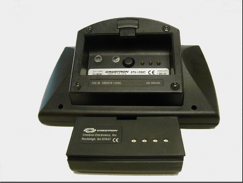
Click to zoom
Application Details
- Equipment Class
- DSR - Part 15 Remote Control/Security Device Transceiver
- Date of Grant
- Mar 10, 2002
- Application Purpose
- Original Equipment
- Date of Application
- Oct 23, 2001
- Equipment Note
- SMARTOUCH RF TOUCHPANEL
- Frequency Range
- 417.80000000 - 418.20000000
- Company
- Crestron Electronics Inc
- Country
- United States
Documents & Files
Document Text
Text extracted from the exhibit documents filed with the FCC. Open a document above to read the original.
Users Manual
This document was prepared and written by the Technical Documentation department at: Crestron Electronics, Inc. 15 Volvo Drive Rockleigh, NJ 07647 1-888-CRESTRON Crestron STX-1550C 2-Way RF Compact Color Touchpanel Operations Guide - DOC. 5812A Contents •• i Contents 2-Way RF Compact Color Touchpanel: STX-1550C 1 Description...........................................................................................................................1 Functional Description............................................................................................1 Physical Description...............................................................................................2 Software.................................................................................................................2 Leading Specifications.........................................................................................................3 General Use and Safety........................................................................................................5 Recommended Touchpanel Cleaning......................................................................5 Applying Power......................................................................................................5 Identity Codes........................................................................................................5 Configuring the Touchpanel.................................................................................................6 Touchscreen Calibration Menu...............................................................................6 Diagnostics Menu...................................................................................................7 Setup Menu............................................................................................................7 Uploading and Upgrading.....................................................................................................9 Hookup and Preparation..........................................................................................9 Uploading a VT Pro-e Project...............................................................................13 Firmware Upgrade................................................................................................14 Programming with SIMPL™ Windows®............................................................................16 Configure STX-1550C Program............................................................................16 Example Program.................................................................................................17 Reserved Join Numbers........................................................................................20 Problem Solving.................................................................................................................21 Troubleshooting....................................................................................................21 Further Inquiries...................................................................................................23 Future Updates.....................................................................................................23 Future Firmware Upgrades....................................................................................23 Appendix...........................................................................................................................24 Overview..............................................................................................................24 VT Pro-e Project...................................................................................................24 SIMPL Program...................................................................................................25 Conclusion: How the Example Works...................................................................26 Return and Warranty Policies.............................................................................................27 Merchandise Returns / Repair Service...................................................................27 Crestron Limited Warranty...................................................................................27 Crestron STX-1550C 2-Way RF Compact Color Touchpanel Operations Guide - DOC. 5812A 2-Way RF Compact Color Touchpanel: STX-1550C •• 1 2-Way RF Compact Color Touchpanel: STX-1550C Description Functional Description The STX-1550C is a 2-way radio frequency (RF) compact color SmarTouch ™ touchpanel that provides a user interface to a Crestron remote control system (herein referred to as the Cresnet system). The touchpanel is a handheld, long range, RF, 2-way wireless transceiver that communicates through a RF gateway/transceiver, STRFGWX (sold separately) to the Cresnet system. The 2-way communications provide the control of the Cresnet devices and provide dynamic onscreen feedback for real-time confirmation of commands. Up to 15 touchpanels can communicate with one STRFGWX. The RF signals can travel from a minimum of three feet up to a maximum of 50 - 75 feet. Additional range can be obtained by using multiple STRFGWX units distributed throughout any particular area or installation. The location and the antenna position of the STRFGWX are important factors in the RF performance. The range of the touchpanel is also dependent on its placement and the construction of the building in which it is used. The STX-1550C touchpanel offers: • 256 color display • Pop-up sub panels to reduce memory requirements, providing optimal speed and performance • Multiple button, slider control, and icon configurations • Up to 999 functions and 96 screens • Imported photographs, drawings, and icons • Support for downloadable fonts - proportional and non-proportional • Foreign language text Included with the STX-1550C is a Crestron High Performance Rechargeable Battery Pack (ST-BTP) a…
Text truncated - open the document above for the full version.
Operational Description
STX-1550C The STX-1550C remote control is a Crestron radio-frequency (RF) 2-way wireless touchpanel that is designed for numerous applications ranging from the boardroom to complete home automation. Electronic devices or subsystems can be controlled from anywhere via the wireless user interface. Users are no longer tethered by a wired control panel or limited to infrared line-of sight control, as with most ordinary wireless controllers. The STX-1550C RF, 2-way wireless transceiver will communicates through a RF gateway/transceiver, STRFGWX to the Cresnet system. The 2-way communications provide the control of the Cresnet devices and provide dynamic onscreen feedback for real-time confirmation of commands.
Parts List/Tune Up Info
C:\WINDOWS\Desktop\PA05730-1.out9/18/01 12:45PM Page: 1 CRESTRON ELECTRONICS, INC. Memo: Please forward printout to clifford Indented Bill of Material Report (Report Parameters) ------------------------------------------------------------------------------------------------------- System-Date: Tue Sep 18 11:14:56 2001 Database Name: /u/titanuat/dg008crtn/g008crtn User Id: clifford Terminal Id: yp45 Function name: indented.bom Parameter list = Parameter Output: to /usr/clifford/PA05730-1.out Report Output: to /usr/clifford/PA05730-1.out Item Group List: * Revision Type: REG Item Number: PA05730-1 To: PA05730-1 Buyer/Planner List: * Effective Date: 09/18/2001 Parent Item Quantity: 1 CRESTRON ELECTRONICS, INC. Indented Bill of Material Report ------------------------------------------------------------------------------------------------------- Item Number: PA05730-1 PCB ASSY, SMARTOUCH, 2 WAY RF Quantity: 1 UO Batch-size: 1 Effective: 01/25/01 Expiration: 12/31/49 Revision ID: K - ECN 2098/TCR1810 Drawing ID: P Buyer/Planner: Item Group: Drawing ID-2: S ------------------------------------------------------------------------------------------------------- Qty/ By- Level Bom-seq Component Description Ext-Qty UOM Ph Pro 1.................. 5 PB05730-1 PCB, SMARTOUCH, 2 WAY RF 1 EA N N 1.................. 15 CFRDC470-5 CAP, CER, 47PF, 3KV, 5%, RDL, 1 EA N N 0.25"LS, 0.330"DX0.187"H C55 1.................. 20 CFRDL270-1 CAP, ELECT, 27UF, 35V, 20%, 3 EA N N RDL, 2MMLS, 5X11MM, LOW IMPD Memo: SECURE TO PCB USING AH C34,C39,C56 1.................. 25 CFRDL331-2 CAP, ELECT, 330UF, 10V, 20%, 1 EA N N RDL,3.5MMLS, 8X11.5MM,LOW IMPD C50 1.................. 30 CFRDL560-2 CAP, ELECT, 56UF, 50V, 20%, 2 EA N N RDL,2.5MMLS, 6.3X15MM,LOW IMPD C:\WINDOWS\Desktop\PA05730-1.out9/18/01 12:45PM Page: 2 C52,C83 1.................. 35 CFSMC050-1 CAP, CER, 5PF, 50V, 0805, COG, 1 EA N N 5%, SM C1 1.................. 40 CFSMC070-1 CAP, CER, 7PF, 50V, 0805, COG, 2 EA N N 5%, SM C44,C45 1.................. 45 CFSMC100-1 CAP, CER, 10PF, 50V, 0805, 3 EA N N COG, 5%, SM C2,C3,C4 1.................. 50 CFSMC101-3 CAP, CER, 100PF, 50V, 0805, 3 EA N N COG, 5%, SM C67,C90,C93 1.................. 51 CFSMC102-2 CAP, CER, 1000PF, 50V, 0805, 1 EA N N X7R, 5%, SM C64 1.................. 60 CFSMC103-3 CAP, CER, 0.01UF, 50V, 0805, 8 EA N N X7R, 5%, SM C5,C9-C12,C63,C72,C81 1.................. 65 CFSMC104-4 CAP, CER, 0.1UF, 50V, 0805, 39 EA N N X7R, 5%, SM C6,C13-C33,C35,C36,C40,C46-C49,C53,C54,C57,C69,C76,C80, 1.................. 70 CFSMC105-1 CAP, CER, 1.0UF, 16V, 0805, 1 EA N N Y5V, +80/-20%, SM C73 1.................. 71 CFSMC150-1 CAP, CER, 15PF, 50V, 0805, 3 EA N N COG, 5%, SM C37,C88,C89 1.................. 75 CFSMC220-1 CAP, CER, 22PF, 50V, 0805, 2 EA N N COG, 5%, SM C70,C71 1.................. 76 CFSMC222-2 CAP, CER, 2200PF, 50V, 0805, 1 EA N N X7R, 10%, SM C82 1.................. 80 CFSMC223-3 CAP, CER, 22000PF, 50V, 0805, 1 EA N N X7R, 10%, SM C65 1.................. 85 CFSMC334-1 CAP, CER, 0.33UF, 50V, 1206, 1 EA N N Z5U, 20%, SM C38 1.................. 86 CFSMC471-1 CAP, CER, 470PF, 50V, 0805, 5 EA N N COG, 5%, SM C91,C92,C94,C95,C96 1.................. 87 CFSMC472-1 CAP, CER, 4700PF, 50V, 0805, 1 EA N N X7R, 5%, SM C66 C:\WINDOWS\Desktop\PA05730-1.out9/18/01 12:45PM Page: 3 1.................. 90 CFSMC5R1-3 CAP, CER, 5.1PF, 50V, 0805, 1 EA N N COG, 0.025PF, SM C78 1.................. 95 CFSMC473-1 CAP, CER, 47000PF, 50V, 1206, 1 EA N N X7R, 10%, SM C7 1.................. 100 CFSMC475-2 CAP, CER, 4.7UF, 16V, 1206, 1 EA N N Y5V, +80% -20%, SM C74 1.................. 105 CFSMF104-1 CAP, FILM, 0.1UF, 50V, 1913, 3 EA N N 5%, SM C60,C61,C62 1.................. 110 CFSMT105-3 CAP, TANT, 1UF, 20V, 3216, 2 EA N N 10%, SM C8,C58 1.................. 115 CFSMT105-7 CAP, TANT, 1UF, 35V, 3528, 3 EA N N 10%, SM C51,C75,C79 1.................. 120 CFSMT106-3 CAP, TANT, 10UF, 10V, 3528, 1 EA N N 10%, SM C68 1.................. 125 CFSMT156-2 CAP, TANT, 15UF, 10V, 6032, 1 EA N N 10%, SM C77 1.................. 130 CFSMT225-1 CAP, TANT, 2.2UF, 10V, 3216, 4 EA N N 20%, SM C41,C42,C43,C59 1.................. 140 DISMG-4002-1 DIODE, SM, 4002, GENERAL, 100V 1 EA N N DL-41 D11 1.................. 145 DISMS-SS14-1 DIODE, SCHOTTKY PRV=40V, Io= 4 EA N N 1A,Ifsm=30A,Vfm=500mV,DO-214AC D3,D5,D13,D15 1.................. 150 DISMS-SS24-1 DIODE, SM, SS24, SCHOTTKY, 2A, 2 EA N N DO-214AA D2,D4 1.................. 155 DISMT-SMBJ8CA-1 DIODE, SM, TRANS SUP, 8.0VWM, 2 EA N N 600W, 5%, BI-DIRECT, DO-214AA CR1,CR2 1.................. 160 DISMW-1N914-1 DIODE, SM, 1N914, SWITCHING, 11 EA N N SOT-23 D1,D6-D10,D12,D14,D16,D17,D18 1.................. 165 DISMZ-5236-1 DIODE, SM, 5236, ZENER, 7.5V, 3 EA N N SOT-23 Z2,Z3,Z4 C:\WINDOWS\Desktop\PA05730-1.out9/18/01 12:45PM Page: 4 1.................. 170 DISMZ-5242-1 DIODE, SM, 5242, ZENER, 12V, 1 EA N N SOT-23 Z1 1.................. 175 DKMS-TR3002-1 XCVR, HYBRID, 418.00MHZ, 3V, 1 EA N N 0.43"LX0.38"WX0.08"H, SM-20L U18 1.................. 180 FBSM-3 F BEAD, 600R MIN IMPD, 2LX 5 EA N N 1.25W MM L1,L8-L11 1.................. 185 FUTHAR10-1 FUSE, 100MA, RESET, 0.29"WX 2 EA N N 0.5"H, 0.2"LS, TH, 7.5 OHMS R52,R53 1.................. 189 ICSMA-ITT002AB-1 IC, ANALOG, SPDT RF SWITCH, 1 EA N N SOIC-8, SM U24 1.................. 190 ICSMC-LT1107CS8-1 IC, CONVERTER, DC/DC, ADJUST, 1 EA N N MICROPOWER, SO-8, SM U11 1.................. 195 ICSMC-LTC1096CS8-1 IC, CONVERTER, A/D, 1INPUT, 1 EA N N 8 BIT, SO 8, SM U6 1.................. 200 ICSMC-MAX522CSA-1 IC, CONVERTER, 8-BIT, DAC, 1 EA N N DUAL VOLT OUTPUT, SO-8, SM U10 1.................. 205 ICSMD-74AC11SC-1 IC, DIGITAL, TRIPLE 3-INPUT 1 EA N N AND GATE, 14 PIN SOIC, SM U8 1.................. 210 ICSMD-74AC14SC-1 IC, DIGITAL, HEX INVERTER, 1 EA N N SCHMITT TRIGGER, SOIC 14, SM U7 1.................. 215 ICSMD-74ACT00SC-1 IC, DIGITAL, QUAD 2-INPUT NAND 1 EA N N GATE, 14 PIN SOIC, SM U26 1.................. 220 ICSMD-74ACT175SC-1 IC, DIGITAL, QUAD D FLIP-FLOP 1 EA N N SO-16, S…
Text truncated - open the document above for the full version.
Test Report
01-0547 Pg 1 TABLE OF CONTENTS SubjectParagraphPage No. Abstract1.02 References2.03 Administrative Information3.04 Test Program Outline4.05 General Test Information5.06 NumberNumber Enclosuresof Pages of Photos (1)Test Equipment List2- (2)Radiated Emission, Intentional Radiator,71 30 MHz to 10 GHz (3)Occupied Bandwidth21 (4)Conducted Emission, 450 kHz to 30 MHz3- (5)A2LA Scope of Accreditation2- 01-0547 Pg 2 1.0 ABSTRACT This report details the results of the FCC Code of Federal Regulations, 47 CFR, Part 15, Sub-Part B and Sub-Part C testing performed on one Smartouch RF Touchpanel, Model No. STX-1550C, Serial No. C562407, manufactured by Crestron Electronics, Inc. operated with one Power Pack with AC Adapter, Model No. 481215003CT, manufactured by Leader Electronics, Inc. The Smartouch RF Touchpanel and the Power Pack with AC Adapter were found to be in compliance with the radiated portions of the FCC Code of Federal Regulations, 47 CFR, Part 15, Sub-Part B for Class B equipment. The Smartouch RF Touchpanel and the Power Pack with AC Adapter were found to be in compliance with the radiated portions of the FCC Code of Federal Regulations, 47 CFR, Part 15, Sub-Part C. The Smartouch RF Touchpanel and the Power Pack with AC Adapter were found to be in compliance with the conducted portions of the FCC Code of Federal Regulations, 47 CFR, Part 15, Sub-Part B, specification limits Class B. The Smartouch RF Touchpanel and the Power Pack with AC Adapter were found to be in compliance with the conducted portions of the FCC Code of Federal Regulations, 47 CFR, Part 15, Sub-Part C. Detailed test results can be observed in Enclosures 2, 3, and 4 of this report. The test results recorded in this report relate only to those items tested. This report shall not be reproduced, except in full, without the written approval of Dayton T. Brown, Inc. 01-0547 Pg 3 2.0 REFERENCES (a)Customer Purchase Order No.:42840 (b)Dayton T. Brown, Inc. Job No.:402394-01-000 (c)Test Specifications:Code of Federal Regulations, 47 CFR, Part 15, Sub-Part C Code of Federal Regulations, 47 CFR, Part 15, Sub-Part B, Class B (d)Test Procedure:American National Standard for Methods of Measurement of Radio-Noise Emissions from Low-Voltage Electrical and Electronic Equipment in the Range of 9 kHz to 40 GHz, ANSI C63.4-1992, dated 17 July 1992 01-0547 Pg 4 3.0 ADMINISTRATIVE INFORMATION Customer:Crestron Electronics, Inc. 15 Volvo Drive Rockleigh, NJ 07647 Test Items:Smartouch RF Touchpanel, Model No. STX-1550C, Serial No. C562407, manufactured by Crestron Electronics, Inc.; and Power Pack with AC Adapter, Model No. 481215003CT, manufactured by Leader Electronics, Inc. Quantity Received:One of Each Test Start Date:16 August 2001 Test Completion Date:17 August 2001 Disposition of Test Items:The test samples were returned to Crestron Electronics, Inc. on 17 August 2001. 01-0547 Pg 5 4.0 TEST PROGRAM OUTLINE Description of Test MethodResults Radiated Emission, Intentional Radiator,Met the specification 30 MHz to 10 GHzrequirements. Occupied BandwidthMet the specification requirements. Conducted Emission, 450 kHz to 30 MHzMet the specification requirements. 01-0547 Pg 6 5.0 GENERAL TEST INFORMATION Setup For the radiated emission test, in the frequency range of 30 to 1000 MHz, the test sample was set up in a climate controlled open field site that measures 44 feet long by 24 feet wide by 24 feet high. For the radiated emission test, in the frequency range of 1 to 10 GHz, the test sample was set up in an anechoic chamber that measures 20 feet wide by 20 feet long by 12 feet high. For the conducted emission test, the test sample was set up within a shielded enclosure which is 20 feet wide by 20 feet long by 12 feet high. All lines carrying power into the shielded enclosure passed through RF suppression filters suitably bonded to the enclosure and capable of 100-dB attenuation over a spectrum of 14 kHz to 10,000 MHz. Unit Operation: Operational Mode Tested - Transmit Mode - The Smartouch RF Touchpanel was transmitting at 417.998 MHz. 01-0547 Enclosure 1 Test Equipment List Test equipment utilized for the program reported herein was within its assigned interval of calibration.Details are on file at Dayton T. Brown, Inc. and will be made available upon request. EQUIPMENT SERIAL CALIBRATION TEST ITEM MANUFACTURER DTB NO. CHARACTERISTIC MODEL NO. DUE DATE CE 20-Foot RG-214 Pasternack 7-9 DC - 1.0 GHz RG214/U 9 7/2/2002 BNC Cable ±1.0 dB RE Cable Dayton T. Brown, Inc. 7-17 DC – 1 GHz 30 Ft - 1/27/2002 ±6 dB RE SMA Cable Insulated Wire, Inc. 7-26 1 – 22 GHz 2505 26 2/24/2002 RE Cable Insulated Wire, Inc. 7-30 900 MHz – 6.5 GHz - 30 3/3/2002 RE BiLog Antenna Chase-York 27-1 30 - 2000 MHz CBL 6112 2055 2/10/2002 RE/OCB Double Ridge Electro-Mechanics Co. 27-41 200 - 2000 MHz 3106 2036 2/24/2002 Waveguide Antenna RE Double Ridge Electro-Mechanics Co. 27-55 1.0 - 18 GHz 3115 2072 12/8/2002 Waveguide Antenna RE Interference Analyzer Electro-Metrics 65-203 9 kHz - 1.0 GHz EMC-30 44137 11/25/2001 Mk IV CE Interference Analyzer Electro-Metrics 65-206 9 kHz - 1.0 GHz EMC-30 44162 10/7/2001 Mk IV RE Preamplifier Hewlett-Packard 71-11 1 - 26.5 GHz 8449B 3008A- 9/29/2002 30 dB Gain 00284 CE Line Impedance Solar Electronics 73-92 10 kHz - 30 MHz 9252-50-R- 951302 10/14/2001 Stabilization Network 50 μ h, 24 Amps 24-BNC Dual LISN CE Screen Room Ace Engineering - 20 ft x 20 ft - Screen - and Machine Company 10 ft High Room 1 01-0547 Enc 1 Pg 1 Test equipment utilized for the program reported herein was within its assigned interval of calibration.Details are on file at Dayton T. Brown, Inc. and will be made available upon request. EQUIPMENT SERIAL CALIBRATION TEST ITEM MANUFACTURER DTB NO. CHARACTERISTIC MODEL NO. DUE DATE RE Anechoic Facility Rayproof - 20 ft x 20 ft - Solid - 12 ft High Room 1 RE FCC Facility Dayton T. Brown, Inc. - 44 ft x 24 ft - FCC - 24 ft High Site RE/OCB Spectrum Analyzer Hewlett-Packard 376636A 9 kHz - 26.5 GHz 8563E 3635A- 1/12/2002 05798…
Text truncated - open the document above for the full version.
Contact Information
Applicant
Chirag Patel(Lead Compliance Engineer)
Test Firm
Dayton T. Brown, Inc.Thomas Arcati
Technical Specifications
| # | Rule Parts | Frequency Range | Power Output |
|---|---|---|---|
| 1 | 15C | 417.8 MHz - 418.2 MHz | - |
Other Applications from Crestron Electronics Inc
EROTSW1580
Jan 29, 202615 inch Touch Screen wall mount
Equipment Class
6XD - 15E 6 GHz Low Power Indoor Client
EROM202108007
Sep 19, 2023Crestron Video Bar with WIFI and Bluetooth
Equipment Class
NII - Unlicensed National Information Infrastructure TX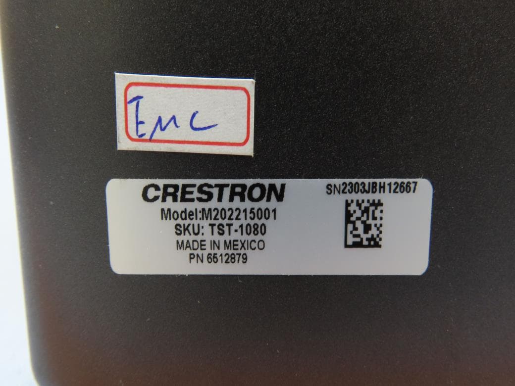
EROM202215001
Jul 05, 202310.1 in. Wireless Touch Screen
Equipment Class
DSS - Part 15 Spread Spectrum Transmitter
EROAM-TX3-200
Jan 13, 2023WIRELESS MEDIA TRANSMITTER
Equipment Class
NII - Unlicensed National Information Infrastructure TX
EROAM-TX3
Jun 06, 2021Wireless Media Transmitter
Equipment Class
DTS - Digital Transmission System