EROTX3Handheld Touchpanel
Crestron Electronics Inc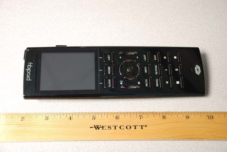
Click to zoom
Application Details
- Equipment Class
- DTS - Digital Transmission System
- Date of Grant
- Sep 30, 2010
- Application Purpose
- Original Equipment
- Date of Application
- Sep 29, 2010
- Equipment Note
- Handheld Touchpanel
- Frequency Range
- 2405.00000000 - 2480.00000000
- Company
- Crestron Electronics Inc
- Country
- United States
Documents & Files
Document Text
Text extracted from the exhibit documents filed with the FCC. Open a document above to read the original.
Users Manual
Crestron MTX-3 Isys™ 2.8” Handheld Wireless Touchpanel Featuring infiNET EX ® Technology Operations Guide This document was prepared and written by the Technical Documentation department at: Crestron Electronics, Inc. 15 Volvo Drive Rockleigh, NJ 07647 1-888-CRESTRON Regulatory Compliance To satisfy RF exposure requirements, this device and its antenna must operate with a separation distance of at least 20 centimeters from all persons and must not be colocated or operating in conjunction with any other antenna or transmitter. Federal Communications Commission (FCC) Compliance Statement Operation is subject to the following two conditions: Industry Canada (IC) Compliance Statement This device complies with part 15 of the FCC Rules. Operation is subject to the following conditions: (1) This device may not cause harmful interference and (2) this device must accept any interference received, including interference that may cause undesired operation. CAUTION: Changes or modifications not expressly approved by the manufacturer responsible for compliance could void the user’s authority to operate the equipment. NOTE: This equipment has been tested and found to comply with the limits for a Class B digital device, pursuant to part 15 of the FCC Rules. These limits are designed to provide reasonable protection against harmful interference in a residential installation. This equipment generates, uses and can radiate radio frequency energy and, if not installed and used in accordance with the instructions, may cause harmful interference to radio communications. However, there is no guarantee that interference will not occur in a particular installation. If this equipment does cause harmful interference to radio or television reception, which can be determined by turning the equipment off and on, the user is encouraged to try to correct the interference by one or more of the following measures: 1. This device may not cause interference, and 2. This device must accept any interference, including interference that may cause undesired operation of the device. Reorient or relocate the receiving antenna Increase the separation between the equipment and receiver Connect the equipment into an outlet on a circuit different from that to which the receiver is connected Consult the dealer or an experienced radio/TV technician for help As of the date of manufacture, the MTX-3 has been tested and found to comply with specifications for CE marking and standards per EMC and Radiocommunications Compliance Labelling. All brand names, product names and trademarks are the property of their respective owners. ©2010 Crestron Electronics, Inc. Crestron MTX-3 Isys™ 2.8” Handheld WirelessTouchpanel Contents Isys™ 2.8” Handheld Wireless Touchpanel Featuring infiNET EX ® Technology: MTX-3 1 Introduction...............................................................................................................................1 Features and Functions................................................................................................1 Applications.................................................................................................................4 Specifications..............................................................................................................5 Physical Description....................................................................................................7 Setup........................................................................................................................................10 Identity Code.............................................................................................................10 Battery Installation....................................................................................................10 Power.........................................................................................................................11 Battery Calibration....................................................................................................12 Optimizing Battery Life............................................................................................12 Configuring the Touchpanel......................................................................................13 General Use and Safety.............................................................................................23 Recommended Cleaning............................................................................................23 Programming Software............................................................................................................24 Earliest Version Software Requirements for the PC.................................................24 Programming with Crestron SystemBuilder..............................................................24 Programming with SIMPL Windows........................................................................24 Programming with VisionTools Pro-e.......................................................................27 Example Program......................................................................................................31 Uploading and Upgrading........................................................................................................32 Establishing Communication.....................................................................................32 Programs, Projects and Firmware..............................................................................33 Program Checks........................................................................................................33 Problem Solving ......................................................................................................................34 Troubleshooting.........................................................................................................34 Reference Documents...........................…
Text truncated - open the document above for the full version.
Users Manual
1 quickstart guide PTX3 PTX3 Prodigy ® Handheld Touchpanel QUICKSTART DOC. 7001A (2027729) 03.10 www.crestron.com/prodigy 888.273.7876 201.767.3400 ©2010 Specifications subject to change without notice. All brand names, product names, and trademarks are the property of their respective owners. The Prodigy ® PTX3 is a versatile yet cost effective home theater remote control. This state of the art handheld two-way controller includes a 2.8” active matrix touchscreen capable of displaying stunning graphics and dynamic text with true feedback. The ergonomic layout of pushbuttons provides intuitive, tactile control for hands and fingers of all sizes. Its compact size and design offer easy one handed operation, while its 802.15.4 wireless technology affords reliable communications over everything from home theater to whole house automation as part of a complete Prodigy system. Introduction 1 Perform the following procedure to install the battery pack in a PTX3 touchpanel: Power A. Install the Battery 3 Configure the Touchpanel 4 The following diagram illustrates a PTX3 in a system with other Prodigy devices. Application 2 1. Place the touchpanel screen side down on a clean, soft surface. 2. Remove the battery compartment cover on the rear of the touchpanel. 3. Carefully connect the multi-pin connector of the battery with the corresponding connector inside the battery compartment. The pin side of the connector should be facing upward (toward the rear of the touchpanel). Red wires should be above black wires (toward the top of the touchpanel). Ensure the connector is fully seated. 4. Place the battery in the compartment, oriented so the wires for the multi-pin connector are on the bottom, as shown in the illustration to the right. 5. Re-attach the battery compartment cover. B. Charge the Battery To charge the battery pack, the PTX3 must be placed on the included PTX3-DS docking station/charger. Connect the included power pack to the PTX3-DS. NOTE: Before using the PTX3 for the first time, charge its battery for a least two hours by placing it on the PTX3-DS docking station/charger. The green LED on the front of the PTX3 will blink while the battery is charging. NOTE: When not using the PTX3, store the unit on its docking station/charger. The setup screen is the starting point for configuring the PTX3. When power is applied for the first time, the screen shown below appears. NOTE: During regular operation of the touchpanel, to activate the setup functions, press hard keys 1, 2, 3, and 4 in sequence twice (i.e. press 1, 2, 3, 4, 1, 2, 3, 4) within a five second period. Touch the screen to display the PTX3 setup screen, as shown in the illustration below. The setup screen enables basic configuration procedures prior to regular operation of the touchpanel. USB Port Location NOTE: USB port for loading projects and upgrading firmware, is located behind the battery compartment cover on the rear of the unit. 4 321 For Regulatory Compliance information, refer to the latest version of Doc. 7002. 2 quickstart guide PTX3 PTX3 QUICKSTART DOC. 7001A (2027729) 03.10 Prodigy ® Handheld Touchpanel www.crestron.com/prodigy 888.273.7876 201.767.3400 ©2010 Specifications subject to change without notice. All brand names, product names, and trademarks are the property of their respective owners. Use the Prodigy Composer software (available for download from www.crestron.com/prodigycomposer) to configure your Prodigy system. A Prodigy Network Setup Wizard is included with Prodigy Composer. Before a PTX3 can be used, it must first be acquired by a PMC2 that is connected to a Prodigy system. To acquire the PTX3, perform the following when prompted by the Prodigy Network Setup Wizard. 1. Put the PMC2 in Acquire mode by pressing its ACQUIRE button (or follow the prompts in the Network Setup Wizard to do this automatically). 2. Put the PTX3 in Acquire mode by doing the following: a. On the main setup screen shown on page 1, touch RF Setup to go to the “RF Setup” screen, shown in illustration below. b. Touch Acquire Gateway. c. The “Confirm Acquire” screen, shown in illustration below, will be displayed. Touch YES, Acquire New Gateway to begin the process. d. The “RF Gateway Acquisition In Progress” screen, shown in illustration below, will be displayed. 5 Acquire the PTX3 7 The following table provides corrective action for possible trouble situations. If further assistance is required, please contact a Crestron customer service representative. Problem Solving Further Inquiries If you cannot locate specific information or have questions after reviewing this guide, please take advantage of Crestron's award winning customer service team by calling Crestron at 1-888-CRESTRON [1-888-273-7876]. You can also log onto the online help section of the Crestron website (www.crestron.com/onlinehelp) to ask questions about Crestron products. First-time users will need to establish a user account to fully benefit from all available features. Future Updates As Crestron improves functions, adds new features and extends the capabilities of the PTX3, additional information may be made available as manual updates. These updates are solely electronic and serve as intermediary supplements prior to the release of a complete technical documentation revision. Check the Crestron website periodically for manual update availability and its relevance. Updates are identified as an “Addendum” in the Download column. Troubleshooting 6 Load the Project Use the Prodigy Composer software (available for download from www.crestron.com/prodigycomposer) to configure your Prodigy system. Refer to the help file for instructions on loading the project. 3. When the acquire is complete, the “RF Setup” screen will show the gateway’s EUID, the channel number and RF ID, as shown in illustration below. Take the PMC2 out of the Acquire mode by pressing its ACQUIRE button (or follow the prompts in the Network Setup Wizard to do this automatically). “RF Setup” Screen“Con…
Text truncated - open the document above for the full version.
Users Manual
As of the date of manufacture, the PTX3 has been tested and found to comply with specifications for CE marking and standards per EMC and Radiocommunications Compliance Labelling. DOC. 7002A (2027730) 03.10 Specifications subject to change without notice. PTX3 Crestron Electronics, Inc. 15 Volvo Drive, Rockleigh, NJ 07647 Tel: 888.CRESTRON Fax: 201.767.7576 www.crestron.com Regulatory Compliance Federal Communications Commission (FCC) Compliance Statement This device complies with part 15 of the FCC Rules. Operation is subject to the following conditions: (1) This device may not cause harmful interference and (2) this device must accept any interference received, including interference that may cause undesired operation. To satisfy RF exposure requirements, this device and its antenna must operate with a separation distance of at least 20 centimeters from all persons and must not be colocated or operating in conjunction with any other antenna or transmitter. CAUTION: Changes or modifications not expressly approved by the manufacturer responsible for compliance could void the user’s authority to operate the equipment. NOTE: This equipment has been tested and found to comply with the limits for a Class B digital device, pursuant to part 15 of the FCC Rules. These limits are designed to provide reasonable protection against harmful interference in a residential installation. This equipment generates, uses and can radiate radio frequency energy and, if not installed and used in accordance with the instructions, may cause harmful interference to radio communications. However, there is no guarantee that interference will not occur in a particular installation. If this equipment does cause harmful interference to radio or television reception, which can be determined by turning the equipment off and on, the user is encouraged to try to correct the interference by one or more of the following measures: Reorient or relocate the receiving antenna Increase the separation between the equipment and receiver Connect the equipment into an outlet on a circuit different from that to which the receiver is connected Consult the dealer or an experienced radio/TV technician for help Industry Canada (IC) Compliance Statement Operation is subject to the following conditions: 1.This device may not cause interference, and 2.This device must accept any interference, including interference that may cause undesired operation of the device. Return and Warranty Policies Merchandise Returns / Repair Service CRESTRON Limited Warranty 1.No merchandise may be returned for credit, exchange or service without prior authorization from CRESTRON. To obtain warranty service for CRESTRON products, contact an authorized CRESTRON dealer. Only authorized CRESTRON dealers may contact the factory and request an RMA (Return Merchandise Authorization) number. Enclose a note specifying the nature of the problem, name and phone number of contact person, RMA number and return address. CRESTRON ELECTRONICS, Inc. warrants its products to be free from manufacturing defects in materials and workmanship under normal use for a period of three (3) years from the date of purchase from CRESTRON, with the following exceptions: disk drives and any other moving or rotating mechanical parts, pan/tilt heads and power supplies are covered for a period of one (1) year; touchscreen display and overlay components are covered for 90 days; batteries and incandescent lamps are not covered. Trademark Information All brand names, product names and trademarks are the sole property of their respective owners. Windows is a registered trademark of Microsoft Corporation. Windows95/98/Me/XP/Vista/7 and WindowsNT/2000 are trademarks of Microsoft Corporation. 2.Products may be returned for credit, exchange or service with a CRESTRON Return Merchandise Authorization (RMA) number. Authorized returns must be shipped freight prepaid to CRESTRON, 6 Volvo Drive, Rockleigh, N.J. or its authorized subsidiaries, with RMA number clearly marked on the outside of all cartons. Shipments arriving freight collect or without an RMA number shall be subject to refusal. CRESTRON reserves the right in its sole and absolute discretion to charge a 15% restocking fee plus shipping costs on any products returned with an RMA. 3.Return freight charges following repair of items under warranty shall be paid by CRESTRON, shipping by standard ground carrier. In the event repairs are found to be non-warranty, return freight costs shall be paid by the purchaser. This warranty extends to products purchased directly from CRESTRON or an authorized CRESTRON dealer. Purchasers should inquire of the dealer regarding the nature and extent of the dealer's warranty, if any. CRESTRON shall not be liable to honor the terms of this warranty if the product has been used in any application other than that for which it was intended or if it has been subjected to misuse, accidental damage, modification or improper installation procedures. Furthermore, this warranty does not cover any product that has had the serial number altered, defaced or removed. This warranty shall be the sole and exclusive remedy to the original purchaser. In no event shall CRESTRON be liable for incidental or consequential damages of any kind (property or economic damages inclusive) arising from the sale or use of this equipment. CRESTRON is not liable for any claim made by a third party or made by the purchaser for a third party. CRESTRON shall, at its option, repair or replace any product found defective, without charge for parts or labor. Repaired or replaced equipment and parts supplied under this warranty shall be covered only by the unexpired portion of the warranty. Except as expressly set forth in this warranty, CRESTRON makes no other warranties, expressed or implied, nor authorizes any other party to offer any warranty, including any implied warranties of merchantability or fitness for a particular purpose. Any implied warranties th…
Text truncated - open the document above for the full version.
Cover Letter(s)
Crestron Electronics, Inc. 15 Volvo Drive Rockleigh, NJ 07647 Tel: 800.237.2041/ 201.767.3400 Fax: 201.767.7576 www.crestron.com September 24, 2010 Federal Communications Commission 7435 Oakland Mills Road Columbia MD 21046 Subject: Request for Confidentiality FCC ID: EROTX3 To Whom It May Concern: Pursuant to the provisions of Sections 0.457 and 0.459 of the Commission’s rules (47 CFR §§ 0.457, 0.459), we are requesting the Commission to permanently withhold the following attachments as confidential document from public disclosure. Schematic Diagram Block Diagram Theory of Operation Above mentioned document contains detailed system and equipment description are considered as proprietary information in operation of the equipment. The public disclosure of above documents might be harmful to our company and would give competitor an unfair advantage in the market. It is our understanding that all measurement test reports, FCC ID label format and correspondent during certification review process cannot be granted as confidential documents and those information will be available for public review once the grant of equipment authorization is issued. Best Regards Crestron Electronics Inc. Grace Lin Sr. Compliance Engineer Email: [email protected] Telephone: 201-750-7004 extension 11464
External Photos
FCC ID: EROTX3 IC: 5683C-TX3 External Photos Page 1 of 3 External Photos FCC ID: EROTX3 IC: 5683C-TX3 External Photos Page 2 of 3 External Photos FCC ID: EROTX3 IC: 5683C-TX3 External Photos Page 3 of 3 External Photos
ID Label/Location Info
FCC ID: EROTX3 IC: 5683C-TX3 ID Label Location Page 1 of 1 ID Label Location
ID Label/Location Info
NOTES: 1. MATERIAL: UL/CSA APPROVED MATTE FINISHED SILVER POLYESTER, .002” THK WITH PERMANENT ACRYLIC ADHESIVE. 2. PRINT: TEXT AND GRAPHICS - BLACK. 3. USE COMPUTER FILE 25280-C.FMT FOR THE ACTUAL PRODUCTION OF THE LABEL. 4. SEE DWG 22121 FOR C-TICK NUMBER TO REPLACE N00000. 5. MADE IN COO: TO BE CHANGED TO COUNTRY OF ORIGIN PRODUCT IS MANUFACTURED IN (EX. USA, CANADA, ETC.) JS 06/23/10 272785 272785-C C PTX36503722 06/23/10 DAP LABEL, BARCODE, 6504593, SORT NAME, SER NO., CE, CTICK, FCC INFO, APX: 2.00”, .50”H DAP 06/28/10 WF FCC ID: EROTX3 IC: 5683C-TX3 06/23/10 MTX-3 6504336 B DAP C WFECN 9581 07/13/10 ECN 9XXX 09/23/10 ORIGINAL ISSUE PER EWO 1698
ID Label/Location Info
NOTES: 1. MATERIAL: UL/CSA APPROVED MATTE FINISHED SILVER POLYESTER, .002” THK WITH PERMANENT ACRYLIC ADHESIVE. 2. PRINT: TEXT AND GRAPHICS - BLACK. 3. USE COMPUTER FILE 24803-C.FMT FOR THE ACTUAL PRODUCTION OF THE LABEL. 4. SEE DWG 22121 FOR C-TICK NUMBER TO REPLACE N00000. 5. MADE IN COO: TO BE CHANGED TO COUNTRY OF ORIGIN PRODUCT IS MANUFACTURED IN (EX. USA, CANADA, ETC.) JS 11/11/09 272247 272247-C C PTX36503722 11/11/09 DAP LABEL, BARCODE, 6504593, SORT NAME, SER NO., CE, CTICK, FCC INFO, APX: 2.00”, .50”H DAP 11/15/09 WF FCC ID: EROTX3 IC: 5683C-TX3 11/11/09 PTX3 6503722 B DAP C WFECN 8923 03/29/10 ECN 9XXX 09/23/10
Internal Photos
FCC ID: EROTX3 IC: 5683C-TX3 Internal Photo Page 1 of 5 Internal Photos FCC ID: EROTX3 IC: 5683C-TX3 Internal Photo Page 2 of 5 Internal Photos FCC ID: EROTX3 IC: 5683C-TX3 Internal Photo Page 3 of 5 Internal Photos FCC ID: EROTX3 IC: 5683C-TX3 Internal Photo Page 4 of 5 Internal Photos FCC ID: EROTX3 IC: 5683C-TX3 Internal Photo Page 5 of 5 Internal Photos
RF Exposure Info
FCC ID: EROTX3 IC: 5683C-TX3 Page 1 of 1 Maximum Permissive Exposure Performance Criterion: The human RF exposure limit is 1 mW/cm 2 . Evaluation Results: Complies Details: The maximum permissible exposure (MPE) is predicted by using Equation (3) of Section 2 of FCC OET Bulletin 65, Edition 97-01: S = PG/4πR 2 where: S = power density (in appropriate units, e.g. mW/cm 2 ) P = power input to the antenna (in appropriate units, e.g., mW) G = power gain of the antenna in the direction of interest relative to an isotropic radiator R = distance to the center of radiation of the antenna (appropriate units, e.g., cm) P = 95.94 mW, G = 1.9724 (2.95 dBi), R = 20 cm S = 0.0374 mW/cm 2 = 0.374 W/m 2 MPE limit for uncontrolled exposure at prediction frequency: 1 mW/cm 2 Maximum allowable antenna gain: 17.19 dBi Margin of Compliance at 20 cm = 14.24 dB
Test Report
FCC ID: EROTX3 IC: 5683C-TX3 Page 1 of 30 Test Report FCC Part 15, Subpart C, Section 15.247 Industry Canada RSS-210, Issue 7 Report Number: TX3-Cert Model: MTX-3, PTX3 FCC ID: EROTX3 IC: 5683C-TX3 Date: September 29, 2010 Prepared by: Grace Lin Date: Sep. 29, 2010 Grace Lin, Sr. Compliance Engineer Reviewed by: Wayne Owens Date: Sep. 29, 2010 Wayne Owens, Director of Program Management FCC ID: EROTX3 IC: 5683C-TX3 Page 2 of 30 Table of Contents 1. GENERAL DESCRIPTION ................................................................................................ 3 1.1 P RODUCT DESCRIPTION................................................................................................... 3 1.2 TEST METHODOLOGY...................................................................................................... 3 1.3 TEST FACILITY................................................................................................................. 3 1.4 TEST EQUIPMENT............................................................................................................. 4 1.5 E VALUATION SUMMARY.................................................................................................. 4 2. SYSTEM TEST CONFIGURATION ................................................................................. 5 2.1 J USTIFICATION................................................................................................................. 5 2.2 BLOCK DIAGRAM............................................................................................................. 5 2.3 EUT EXERCISE SOFTWARE AND MODE(S) OF OPERATION.............................................. 5 2.4 C ABLES............................................................................................................................ 6 2.5 S PECIAL ACCESSORIES..................................................................................................... 6 2.6 SUPPORT EQUIPMENT....................................................................................................... 6 2.7 EQUIPMENT MODIFICATIONS........................................................................................... 6 3. EVALUATION .....................................................................................................................7 3.1 ANTENNA REQUIREMENTS............................................................................................... 7 3.2 6 DB BANDWIDTH........................................................................................................... 8 3.3 99% BANDWIDTH.......................................................................................................... 11 3.4 POWER OUTPUT............................................................................................................. 13 3.5 BAND EDGE................................................................................................................... 16 3.6 CONDUCTED SPURIOUS EMISSIONS................................................................................ 18 3.7 P OWER SPECTRAL DENSITY........................................................................................... 22 3.8 RADIATED SPURIOUS EMISSIONS................................................................................... 25 3.9 TRANSMITTER AC POWER LINE CONDUCTED EMISSIONS.............................................. 27 3.10 RECEIVER RADIATED EMISSIONS................................................................................... 28 3.11 R ECEIVER AC POWER LINE CONDUCTED EMISSIONS.................................................... 30 FCC ID: EROTX3 IC: 5683C-TX3 Page 3 of 30 1. General Description 1.1 Product Description The equipment under test (EUT) is a 2.8" Handheld Touchpanel, models: MTX-3 (with J3 installed) and PTX3 (with J3 uninstalled) is a wireless controller for home theater, home automation, and AV presentation. 1.2 Test Methodology Measurements were performed according to the following procedures and standards: 1) ANSI C63.4: 2003 2) FCC Procedure, “Measurement of Digital Transmission Systems Operating under Section 15.247”, March 23, 2005 3) Industry Canada RSS-Gen Issue 2 4) Industry Canada RSS-210 Issue 7 5) Industry Canada ICES-003 Issue 4 All measurements were performed in a 3-meter semi-anechoic chamber and the control room. Prescan was performed on both the MTX-3 and the PTX3. The worst-case data was reported/recorded. 1.3 Test Facility The 3-meter semi-anechoic chamber used to collect conducted and radiated emission data is located at 22 Link Drive, Rockleigh, New Jersey. This test facility has been placed on file with the FCC, Registration Number: 412871, and Industry Canada, Site Number: 5683C-1. FCC ID: EROTX3 IC: 5683C-TX3 Page 4 of 30 1.4 Test Equipment Description Model Serial No. Frequency Range Calibration Date R&S EMI Receiver ESU40 100076 20 Hz – 40 GHz Dec. 22, 2009 Teseq Bilog Antenna CBL 6112D 25231 30 MHz – 2 GHz Jan. 28, 2010 ETS-Lindgren Double Ridge Horn Antenna 3117 00047560 1 GHz – 18 GHz Jan. 27, 2010 R&S Preamplifier TS-PR18 100044 30 MHz – 18 GHz Feb. 9, 2010 ETS-Lindgren Standard Gain Horn Antenna 3160-09 00078911 18 GHz – 26.5 GHz May 10, 2010* R&S Preamplifier TS-PR26 100030 18 GHz – 26.5 GHz Feb. 23, 2010 Solar Electronics LISN 9252-50-R-24-N 068546 10 kHz – 50 MHz Feb. 3, 2010 * Visual inspection 1.5 Evaluation Summary Rule Section FCC IC Description/Parameters Results §15.203 N/A Antenna Requirement Complies §15.247(a)(2) §A8.2(a) of RSS-210 6 dB Bandwidth, 500 kHz Complies N/A §4.6.1 of RSS-Gen 99% Occupied Bandwidth (for reporting purpose) §15.247(b)(3) §A8.4(4) of RSS-210 Power Output, conducted, 1 Watt (30dBm) Complies §15.247(d) §2.1, §A8.5 of RSS- 210 Band Edge Complies §15.247(d) §A8.5 of RSS-210 Conducted Spurious Emissions, 20 dBc Complies §15.247(e) §A8.2(b) of RSS-210 Power Spectral Density (PSD), 8 dBm in any 3 kHz band. Complies §15.205, §15.209, §15.247(d) §2.2, §2.7, §A8.5 of …
Text truncated - open the document above for the full version.
Test Setup Photos
FCC ID: EROTX3 IC: 5683C-TX3 Test Setup Photos Page 1 of 2 Test Setup Photos Conducted Emission Configuration Photographs Worst-case conducted emission, front view Worst-case conducted emission, Side View FCC ID: EROTX3 IC: 5683C-TX3 Test Setup Photos Page 2 of 2 Test Setup Photos Radiated Emission Configuration Photographs Worst-case radiated emission, front view Worst-case radiated emission, rear view
Contact Information
Applicant
Chirag Patel(Lead Compliance Engineer)
Test Firm
Crestron Electronics, Inc.Mairaj Hussain
[email protected]201-750-7004
Technical Specifications
| # | Rule Parts | Frequency Range | Power Output |
|---|---|---|---|
| 1 | 15C | 2.40 GHz - 2.48 GHz | 95.94 mW |
Other Applications from Crestron Electronics Inc
EROTSW1580
Jan 29, 202615 inch Touch Screen wall mount
Equipment Class
6XD - 15E 6 GHz Low Power Indoor Client
EROM202108007
Sep 19, 2023Crestron Video Bar with WIFI and Bluetooth
Equipment Class
NII - Unlicensed National Information Infrastructure TX
EROM202215001
Jul 05, 202310.1 in. Wireless Touch Screen
Equipment Class
DSS - Part 15 Spread Spectrum Transmitter
EROAM-TX3-200
Jan 13, 2023WIRELESS MEDIA TRANSMITTER
Equipment Class
NII - Unlicensed National Information Infrastructure TX
EROAM-TX3
Jun 06, 2021Wireless Media Transmitter
Equipment Class
DTS - Digital Transmission System