EROUC-2Tabletop Conference System
Crestron Electronics Inc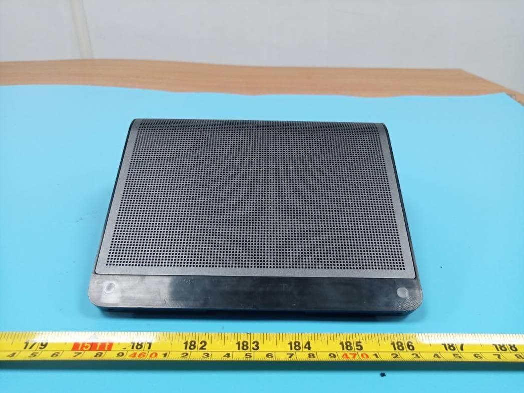
Click to zoom
Application Details
- Equipment Class
- NII - Unlicensed National Information Infrastructure TX
- Date of Grant
- May 07, 2020
- Application Purpose
- Original Equipment
- Date of Application
- May 07, 2020
- Equipment Note
- Tabletop Conference System
- Frequency Range
- 5745.00000000 - 5825.00000000
- Company
- Crestron Electronics Inc
- Country
- United States
Documents & Files
Document Text
Text extracted from the exhibit documents filed with the FCC. Open a document above to read the original.
Users Manual
For Certification, Warranty and RMA information, please visit crestron.com Crestron Electronics, Inc. 15 Volve Drive Rockleigh, NJ 07647. USA 800.237.2041 201.767.3400 crestron.com In all EU member states, operation of 5150 - 5350 MHz is restricted to indoor use only. M201928001 Tabletop Meeting Device Quick Start Guide UC-2 Quick Start Hardware Hookup Make connections as shown in the following diagram. If using the included power supply to provide PoE to the UC-2, connect the supply as shown below. Connec t a laptop computer with the included USB cable to the USB port and use the laptop’s UC software for a conference call. Laptop Powerover Ethernet (P oE) UC-2LAN port Power supply LAN DATA Sign In 1. Use your Microsoft Teams™ software credentials to log into the unit. Use Your Laptop’s UC Software The UC-2 can also be used as an audio peripheral for your laptop computer’s UC software to make a call. 1. Connect the USB cable to the computer. 2. On the computer’s UC software, select “Crestron UC-2 (Echo Canceling Speakerphone)” as the audio device. The UC -2 can now be used as an audio peripheral. UC-2 Specifications Display: Touch Screen: 7" capacitive touch screen (5 points of simultaneous contact) LCD: 1280×800 resolution Audio: Speaker: 4 ohm, 7 W Speaker Microphone: Four Digital I2S MEMS sensor, Sensitivity -26dB, SNR 64dBA Processor: Type: Dual-core Cortex-A72 and Quad-core Cortex-A53 Basic Frequency: 1.8 GHz Memory: RAM: 2GB DDR3L RAM (256Mb x 16bit x 4) Flash: 16GB Communications: Wi -Fi®: Dual-band 802.11a/b/g/n/ac (2.4GHz & 5GHz) Bluetooth®: Bluetooth V5.0+EDR Ethernet: 10/100/1000Mbps PoE Input: Max Input voltage: 57 V Integrated PoE: 802.3af Class 3 and 802.3at, Class 4 P o rt s: Ethernet: (1) RJ-45, 100/1000 Mbps Base-T Ethernet port with LED status indicators USB: (1) Micro USB port Security: (1) Kensigton™ security port Environment: Operating Temperature: 32° to 104° F (0 ° to 40° C) Operating Humidity: 10% to 90% (non-condensing) Dimensions: Height: 3.02 in. (76 mm) Width: 7.17 in. (182 mm) Depth: 9.61 in. (244 mm) 9. 61 in. (244 mm) 7. 17 in. (182 mm) 3. 02 in. (7 6 mm) Crestron Flex TabletopConferenceSystem D ocType-8624A (2055149) 03.20 GettingStarted ScantheQRcodetoviewtheQuickStartGuide. www.crestron.com/docs/8625 Foradditionalinformation,visit www.crestron.com/model/6510609. CertificationandCompliance RegulatoryModel:M201928001 FederalCommunicationsCommission(FCC) ComplianceStatement Thisdevicecomplieswithpart15oftheFCCRules. Operationissubjecttothefollowingconditions: (1)Thisdevicemaynotcauseharmfulinterference and(2)thisdevicemustacceptanyinterference received,includinginterferencethatmaycause undesiredoperation. CAUTION:Changesormodificationsnotexpressly approvedbythemanufacturerresponsiblefor compliancecouldvoidtheuser’sauthorityto operatetheequipment. NOTE: Thisequipmenthasbeentestedandfound tocomplywiththelimitsforaClassBdigitaldevice, pursuanttopart15oftheFCCRules.Theselimits aredesignedtoprovidereasonableprotection againstharmfulinterferenceinaresidential installation.Thisequipmentgenerates,usesand canradiateradiofrequencyenergyand,ifnot installedandusedinaccordancewiththe instructions,maycauseharmfulinterferenceto radiocommunications.However,thereisno guaranteethatinterferencewillnotoccurina particularinstallation.Ifthisequipmentdoescause harmfulinterferencetoradioortelevision reception,whichcanbedeterminedbyturningthe equipmentoffandon,theuserisencouragedtotry tocorrecttheinterferencebyoneormoreofthe followingmeasures: lReorientorrelocatethereceivingantenna. lIncreasetheseparationbetweentheequipment andreceiver. lConnecttheequipmentintoanoutletona circuitdifferentfromthattowhichthereceiver isconnected. lConsultthedealeroranexperiencedradio/TV technicianforhelp. IndustryCanada(IC)ComplianceStatement CANICES-3(B)/NMB-3(B) ThisproductisListedtoapplicableUL®Standards andrequirementstestedbyUnderwriters LaboratoriesInc. Ceproduitesthomologuéselonlesnormesetles exigencesULapplicablesparUnderwriters LaboratoriesInc. ISEDC Caution: This device complies with Innovation, Science, and Economic Development Canada licence-exempt RSS standard(s). Operation is subject to the following two conditions: (1) this device may not cause interference, and (2) this device must accept any interference, including interference that may cause undesired operation of the device. ISEDC RF Exposure Statement: The device is in compliance with RF exposure guidelines, users can obtain Canadian information on RF exposure and compliance. This equipment complies with radiation exposure limits set forth for an uncontrolled environment. This transmitter must not be co-located or operating in conjunction with any other antenna or transmitter. This equipment should be installed and operated with minimum distance 20cm between the radiator& your body. The minimum distance from body to use the device is 20cm. Après examen de ce matériel aux conformité ou aux limites d’intensité de champ RF, les utilisateurs peuvent sur l’exposition aux radiofréquences et la conformité and compliance d’acquérir les informations correspondantes. La distance minimale du corps à utiliser le dispositif est de 20cm. 5150-5350 MHz is restricted to indoor use only. CrestronElectronics,Inc. 15VolvoDrive,Rockleigh,NJ07647 Tel:888.CRESTRON Fax:201.767.7656 www.crestron.com ProductInformation-Doc.8624A (2055149) 03/12/20 Legal Theproductwarrantycanbefoundat www.crestron.com/warranty . ThespecificpatentsthatcoverCrestronproducts arelistedatwww.crestron.com/legal/patents. CertainCrestronproductscontainopensource software.Forspecificinformation,visit www.crestron.com/opensource. CrestronandtheCrestronlogoareeither trademarksorregisteredtrademarksofCrestron Electronics,Inc.intheUnitedStatesand/orother countries.TheETLlogoiseitheratrademarkor registeredtrademarkofIntertekTestingServices NAintheUnitedStatesand/orothercountries.UL andtheULlogoareeithertrademarksorregistered trademarksofUnderwritersLaboratories,Inc.in theUnitedStatesand/…
Text truncated - open the document above for the full version.
External Photos
EXHIBIT B - EUT EXTERNAL PHOTOGRAPHS
ID Label/Location Info
EXHIBIT A - FCC ID LABEL AND LOCATION FCC ID Label FCC ID Label Location Information The label shown shall be permanently affixed at a conspicuous location on the device and be readily visible to the user at the time purchase (Labeling requirements per 2.925)
Internal Photos
EXHIBIT C - EUT INTERNAL PHOTOGRAPHS Bluetooth/Wi-Fi Antenna
RF Exposure Info
Bay Area Compliance Laboratories Corp. (Shenzhen) Report No.: RSZ200120001-00D FCC Part 15.407 Page 16 of 126 1.1307 (b) (1) & §2.1091- MAXIMUM PERMISSIBLE EXPOSURE (MPE) Applicable Standard According to subpart 1.1307 (b)(1), 2.1091 systems operating under the provisions of this section shall be operated in a manner that ensures the public is not exposed to RF energy level in excess of the communication guidelines. Limits for General Population/Uncontrolled Exposure Limits for General Population/Uncontrolled Exposure Frequency Range (MHz) Electric Field Strength (V/m) Magnetic Field Strength (A/m) Power Density (mW/cm 2 ) Averaging Time (Minutes) 0.3-1.34 614 1.63 *(100) 30 1.34-30 824/f 2.19/f *(180/f 2 ) 30 30-300 27.5 0.073 0.2 30 300-1500 / / f/1500 30 1500-100,000 / / 1.0 30 f = frequency in MHz * = Plane-wave equivalent power density Result Calculated Formulary: Predication of MPE limit at a given distance S = 2 4R PG S = power density (in appropriate units, e.g. mW/cm 2 ) P = power input to the antenna (in appropriate units, e.g., mW). G = power gain of the antenna in the direction of interest relative to an isotropic radiator, the power gain factor, is normally numeric gain. R = distance to the center of radiation of the antenna (appropriate units, e.g., cm) Frequency (MHz) Antenna Gain Tune up conducted power Evaluation Distance (cm) Power Density (mW/cm 2 ) MPE Limit (mW/cm 2 ) (dBi) (numeric) (dBm) (mW) 5150-5250 5.0 3.16 15.0 31.62 20 0.0199 1 5250-5350 5.0 3.16 13.0 19.95 20 0.0125 1 5470-5725 5.0 3.16 15.0 31.62 20 0.0199 1 5725-5850 5.0 3.16 14.0 25.12 20 0.0158 1 Note: The 2.4G Wi-Fi can’t transmit with the 5G Wi-Fi at the same time. To maintain compliance with the FCC’s RF exposure guidelines, place the equipment at least 20cm from nearby persons. Result: Compliance
Test Report
FCC PART 15.407 DYNAMIC FREQUENCY SELECTION TEST REPORT For Crestron Electronics Inc 15 Volvo Drive, Rockleigh, New Jersey, 07647, USA FCC ID: EROUC-2 Report Type: Original Report Product Type: Tabletop Conference System Report Number: RSZ200120002-00A Report Date: 2020-03-03 Reviewed By: Ivan Cao Assistant Mana ger Test Laboratory: Bay Area Compliance Laboratories Corp. (Dongguan) No.69 Pulongcun, Puxinhu Industry Area, Tangxia, Dongguan, Guangdong, China Tel: +86-769-86858888 Fax: +86-769-86858891 www.baclcorp.com.cn Bay Area Compliance Laboratories Corp. (Dongguan) Report No.: RSZ200120002-00A FCC Part 15.407 DFS Test Report Page 2 of 20 TABLE OF CONTENTS GENERAL INFORMATION ....................................................................................................................................... 3 PRODUCT DESCRIPTION FOR EQUIPMENT UNDER TEST (EUT) ..................................................................................... 3 OBJECTIVE ................................................................................................................................................................... 3 TEST METHODOLOGY .................................................................................................................................................. 3 TEST FACILITY ............................................................................................................................................................. 4 DECLARATIONS ............................................................................................................................................................ 4 SYSTEM TEST CONFIGURATION .......................................................................................................................... 5 DESCRIPTION OF TEST CONFIGURATION ...................................................................................................................... 5 EUT EXERCISE SOFTWARE .......................................................................................................................................... 5 EQUIPMENT MODIFICATIONS ....................................................................................................................................... 5 SUPPORT EQUIPMENT LIST AND DETAILS .................................................................................................................... 5 EXTERNAL CABLE ........................................................................................................................................................ 5 SUMMARY OF TEST RESULTS ............................................................................................................................... 6 APPLICABLE STANDARDS ........................................................................................................................................ 7 DFS REQUIREMENT ..................................................................................................................................................... 7 DFS MEASUREMENT SYSTEM .................................................................................................................................... 11 SYSTEM BLOCK DIAGRAM ......................................................................................................................................... 11 CONDUCTED METHOD ............................................................................................................................................... 12 RADIATED METHOD ................................................................................................................................................... 13 TEST PROCEDURE ...................................................................................................................................................... 13 TEST RESULTS .......................................................................................................................................................... 14 DESCRIPTION OF EUT ................................................................................................................................................ 14 TEST EQUIPMENT LIST AND DETAILS ......................................................................................................................... 14 RADAR WAVEFORM CALIBRATION ............................................................................................................................ 15 TEST ENVIRONMENTAL CONDITIONS ......................................................................................................................... 15 CHANNEL MOVE TIME AND CHANNEL CLOSING TRANSMISSION TIME ............................................. 17 TEST PROCEDURE ...................................................................................................................................................... 17 TEST RESULTS ........................................................................................................................................................... 17 NON-OCCUPANCY PERIOD ................................................................................................................................... 20 TEST PROCEDURE ...................................................................................................................................................... 20 TEST RESULT ............................................................................................................................................................. 20 Bay Area Compliance Laboratories Corp. (Dongguan) Report No.: RSZ200120002-00A FCC Part 15.407 DFS Test Report Page 3 of 20 GENERAL INFORMATION Product Description for Equipment under Test (EUT) Product Tabletop Conference System EUT Model: M201928001 Rated Input Voltage: DC 48V from POE Adapter Adapter Information Model:G0720-480-050 Inpu…
Text truncated - open the document above for the full version.
Test Setup Photos
EXHIBIT D - TEST SETUP PHOTOGRAPHS Conducted Emissions - Front View Conducted Emissions - Side View Radiated Emissions View (Below 1 GHz) Radiated Emissions View (Above 1 GHz)
Contact Information
Applicant
Chirag Patel(Lead Compliance Engineer)
Test Firm
Bay Area Compliance Laboratories Corp. (Shenzhen)Well Wang
[email protected]+86 (0) 755 33320018
Technical Specifications
| # | Rule Parts | Frequency Range | Power Output |
|---|---|---|---|
| 4 | 15E | 5.75 GHz - 5.83 GHz | 22.00 mW |
Other Applications from Crestron Electronics Inc
EROTSW1580
Jan 29, 202615 inch Touch Screen wall mount
Equipment Class
6XD - 15E 6 GHz Low Power Indoor Client
EROM202108007
Sep 19, 2023Crestron Video Bar with WIFI and Bluetooth
Equipment Class
NII - Unlicensed National Information Infrastructure TX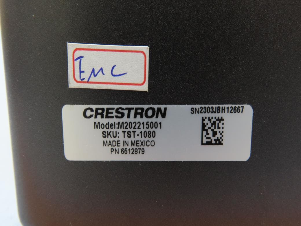
EROM202215001
Jul 05, 202310.1 in. Wireless Touch Screen
Equipment Class
DSS - Part 15 Spread Spectrum Transmitter
EROAM-TX3-200
Jan 13, 2023WIRELESS MEDIA TRANSMITTER
Equipment Class
NII - Unlicensed National Information Infrastructure TX
EROAM-TX3
Jun 06, 2021Wireless Media Transmitter
Equipment Class
DTS - Digital Transmission System