ESV-0117-06Fall Detection and Personal Help Button
Bosch Security Systems LLC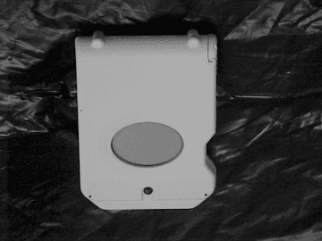
Click to zoom
Application Details
- Equipment Class
- DSC - Part 15 Security/Remote Control Transmitter
- Date of Grant
- Aug 13, 2001
- Application Purpose
- Original Equipment
- Date of Application
- Aug 13, 2001
- Equipment Note
- Fall Detection and Personal Help Button
- Frequency Range
- 304.00000000 - 304.00000000
- Company
- Bosch Security Systems LLC
- Country
- United States
Documents & Files
Document Text
Text extracted from the exhibit documents filed with the FCC. Open a document above to read the original.
Users Manual
SEFD1 Fall Detection and Personal Help Button User Guide Page 2 P/N #####B© 2001 Detection Systems, Inc.SEFD1 User Guide Disclaimer Regarding Fall Detection Warning: The SEFD1 Fall Detection Device assists in automatically detecting conditions where the unit experiences a change in angle combined with a force exceeding a certain G force measurement. This reduces, but does not eliminate the risk, that an individual may experience an event where they require emergency assistance but are unable to obtain assistance on their own. There is a risk that the Fall Alert may not send an emergency signal in the event of a fall or a manual activation resulting in no emergency response despite a true emergency. A false alarm from the Fall Alert system could summon emergency help that is not needed and may result in false alarm fines or damage from forcible entry of emergency personnel into your home. The user recognizes that a properly installed and maintained personal security system may only reduce the risk of events such as burglary, robbery, personal injury and fire. It does not insure or guarantee that there will be no death, personal injury and/or damage to property as a result. Detection Systems does not claim that the Product may not be compromised and/or circumvented, or that the Product will prevent any death, personal and/or bodily injury and/or damage to property resulting from burglary, robbery, fire or otherwise, or that the Product will in all cases provide adequate warning or protection. FCC Compliance Notice This device complies with Part 15 of the FCC Rules. Operation is subject to the following two conditions: (1) this device may not cause harmful interference, and (2) this device must accept any interference received, including interference that may cause undesired operation. The user is cautioned that changes or modifications to the device not expressly approved by the manufacturer could void the user’s authority to operate the equipment. SEFD1 User Guide© 2001 Detection Systems, Inc.Page 3 P/N #####B Calls for Help Even When You Cannot The SEFD1 Fall Detection and Personal Help Button provides assistance that no other personal help button can offer. The pendant alerts your emergency monitoring service automatically when it detects a fall, even if you are able to push the help button on the pendant. The SEFD1 is designed to work in and immediately around your home. The pendant must be close enough to the receiver for a help signal to be transmitted. The coverage area of the pendant will vary from one home to another. It is important for you to know the effective range of your pendant. The SEFD1 is designed to detect falls that meet certain criteria. It may not detect every fall, especially slight falls that are generally not disabling. The SEFD1 Fall Detection device may also generate a fall alarm when you have not fallen. For example, if the pendant drops on the floor, the device may alert the monitoring center that you have fallen. Operation The SEFD1 pendant transmits three conditions: •Push Button •Fall •Low Battery Safety Instructions for the SEFD1 1.Please read all instructions carefully 2.Test the range of the unit upon installation of the system. 3.Test the operation of the unit in connection with the monitoring company’s instructions. 4.The unit is not intended to be machine washed or dried. 5.Do not open the unit except to replace the batteries. Modifying or tampering with teh contents of the unit may cause a malfunction or damage to the unit. 6.Use only fresh, AAA alkaline batteries. Page 4 P/N #####B© 2001 Detection Systems, Inc.SEFD1 User Guide How to Wear the SEFD1 The Fall Detection pendant automatically senses the conditions of a fall and sends an emergency alert when a fall occurs. To send an alarm that you have fallen, you must wear the pendant on your torso in an upright position. Do not wear the pendant on your arm or leg as the device may produce a false alarm or fail to alarm upon a real fall. Wearing the pendant in an incorrect position may cause it to not function properly. Suggested locations for wearing the SEFD1: •On Your Waist: The SEFD1 can be attached to a belt or the waistband of your pants. A belt clip is provided, designed to easily attach to a belt. To attach the pendant to a belt, pull the clip away from the device and slip it over the belt, or turn the device sideways and rotate it to slide it onto the belt (see below). •In a Shirt Pocket: The SEFD1 may be clipped to a shirt pocket. This option works best when the device rests on the inside of the pocket with the button facing your chest. SEFD1 User Guide© 2001 Detection Systems, Inc.Page 5 P/N #####B •On a Fabrifoam Belt: The SEFD1 can be attached to a fabrifoam belt accessory that is worn on the inside or outside of your clothing. This belt is purchased separately. •On a Brassiere/Garment Clip: If visibility is an issue, the SEFD1 can be worn underneath your clothing using a factory-installed, optional brassiere/garment clip. The clip is attached to the front of the device and the belt clip may be removed. Use the garment clip to attach the device to a brassiere to discreetly wear the pendant without compromising your safety or health. This clip may also be used to attach the device to a fabrifoam belt with a smaller profile than the belt clip. Battery Life of the SEFD1 The SEFD1 battery life is approximately 45 to 60 days. The device is always on and the Fall Detection sensor constantly monitors your position while you wear it. Low Battery Warnings When the SEFD1 senses that the AAA batteries inside the unit are low, the LED at the top of the unit flashes once per second until the battery is completely drained. The SEFD1 also sends a low battery signal to the base station which is then sent to the monitoring center. The monitoring center will call you at a convenient time to remind you to replace the batteries. CAUTION:If the SEFD1 is not in rnage of the base station when the battery is low,…
Text truncated - open the document above for the full version.
Block Diagram
BLOCK DIAGRAM of the HEALTH SENSOR 100 Internal wire antenna RF @304 Mhz Enable From u ProcessorDigital Modulation Data Packet SAW Osc. 304 MHz Fixed tuned to 304 Mhz Matching network Transistor Amp. AM Modulated 3.3 VDC Matching network
ID Label/Location Info
ECR# DR AUTHDATESYMREVISION RECORD LOT: ZZZ 1. Use blank label 48285. 2. Ribbon must be PN 40893. 3. WWWWWW is different for every unit and defines the program ID for system usage. 4. ZZZ represents the production lot number. 5. XXYY = Mfg Date Code. 6. CCCCCCCC is printed only after product has Industry and Science Canada approval. ID: WWWWWWWWW CANADA CCCCCCCCCC SEFD1 EEV EEV BK HZ ACCEPTED DRAWING ADDED FCC ID NUMBER B C 5/29/01 7/6/01 PROPRIETARY DATA DATA CONTAINED HEREIN SHALL NOT BE USED, DUPLICATED OR DISCLOSED IN WHOLE OR PART OUTSIDE OF DETECTION SYSTEMS, INC., WITHOUT EXPRESSED WRITTEN PERMISSION OF SAME. N633 DATE: XXYY FCC ID: ESV-0117-06 BATTERY: AAA 13186 1.5 (3.81) .125 (.32) DATE DRAWN DRAWING TITLE SCALE 2:1 DETECTION SYSTEMS, INC., 130 PERINTON PARKWAY FAIRPORT, NEW YORK, 14450, USA (716) 223 4060, FAX (716) 223 9180 PART NO. 48284C 5/29/01 DWG- SEFD1 GEN ID SHEET 1 OF 1 DRAWING NUMBER DRAWN BY: EEV APPR BY: A48284 Rev. C
Operational Description
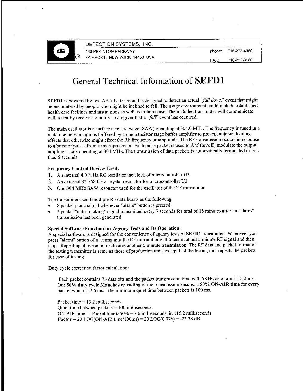
® DETECTION SYSTEMS, INC. 130 PERINTON PARKWAY FAIRPORT, NEW YORK 14450 USA phone: 716-223-4060 FAX: 716-223-9180 eng/vol1/wireless/gendocs/protocol/RF_5kbps_tx_info.doc General RF Alarm Devices Information for 5kbps 1. Data Modulation The data is modulated using the Manchester on/off keyed encoding scheme with 50% duty cycle shown below. The on-air format is defined with a ‘1’ bit which is carrier turning on at the bit center and a ‘0’ bit which is carrier turning off at the bit center. 1 0 1 1 0 0 1 0 1 0 200us 100us 100us 200us 2. Message, Packet and Inter-Packet A packet consists of all on-air bits that are transmitted to provide the system with the current status of a transmitter. A single message is composed of up to 8 packets of the same data. The time between packets is defined as a pseudo- random time length between 100 milliseconds and 275 milliseconds. Message < 8 Packets t p < 20ms t ip = 100ms - 275ms t p t ip 3. Transmission A message will be transmitted when a control signal has changed, a system integrity test takes place or the supervisory time has expired. Control Signal / Recognition Code A single message, of up to 8 packets, will be transmitted when the control signal changes in a transmitter or a repeater. Up to 8 packets of recognition code will also be transmitted by the repeaters to ensure system integrity. < 8 Packets Supervisory To verify system integrity, the state of the inputs will be transmitted periodically. These transmissions consist of not more than 4 packets and will occur not less than every 60 minutes. < 4 Packets > 60 minutes < 4 Packets Note: Packet width of < 20ms with 50% duty cycle Manchester modulation makes the on-air time < 10ms. Therefore, no transmission has more than 10ms of on time out of 100ms. Note: figure not drawn to scale Note: figure not drawn to scale Note: figure not drawn to scale Note: figure not drawn to scale
Test Report
Retlif Testing Laboratories R Test Report No. R-9089-3 FCC ID: ESV-0117-05 APPLICANT Detection Systems, Inc. 130 Perinton Parkway Fairport, NY 14450 MANUFACTURER Detection Systems, Inc. 130 Perinton Parkway Fairport, NY 14450 TEST SPECIFICATION: FCC Rules and Regulations Part 15, Subpart C, Para. 15.231 TEST PROCEDURE: ANSI C63.4:1992 TEST SAMPLE DESCRIPTION BRANDNAME: Detection Systems, Inc. MODEL: SEFD1 TYPE: Pulsed RF Transmitter POWER REQUIREMENTS: 3 V derived from 2 “AAA” batteries FREQUENCY OF OPERATION: 304 MHz TESTS PERFORMED Para. 15.231(a), Radiated Emissions, Fundamental and Harmonics Para. 15.231(b), Radiated Emissions, Spurious Case Para. 15.231(c), Occupied Bandwidth Duty Cycle Determination REPORT OF MEASUREMENTS Applicant: Detection Systems, Inc. Device:Pulsed RF Transmitter FCC ID: ESV-0117-06 Retlif Testing Laboratories R Test Report No. R-9089-3 FCC ID: ESV-0117-05 REPORT OF MEASUREMENTS (continued) TEST RESULTS 15.231 (a) -The device is used as a transmitter for security purposes. 15.231 (a)(1) & -The transmitter is manually operated and ceases transmission within 5 15.231(2)seconds after deactivation. 15.231 (a)(3) -The transmitter does perform periodic transmissions not more than once every 60 minutes. 15.231 (a)(4)-The device is employed for RC purposes involving security and when activated to signal an alarm, operates during the pendency of the alarm condition. 15.231 (b) -The fundamental field strength did not exceed 5580 μV/M (Average) at a test distance of 3 meters. In addition, the requirements of section 15.35 for averaging pulsed emissions and for limiting peak emissions were met. The field strength of harmonic and spurious emissions did not exceed 558 μV/M (AVERAGE). 15.231 (c) -The device operates at 304 MHz. The bandwidth of emissions did not exceed 0.25% of the operating frequency (760 kHz). DETERMINATION OF FIELD STRENGTH LIMITS The field strength limits shown below are found in Section 15.231. Frequency Limit F1=2603750=L1 Fo=310Lo F2=47012500=L2 The formula below was utilized to determine the limits: Limit = L1 + [(Fo-F1)(L2-L1)/(F2-F1)] Solving yields: Fundamental Limit= 5,580 μV/M (AVERAGE) @ 3 Meters Harmonic Limit= 558 μV/M (AVERAGE) @ 3 Meters Retlif Testing Laboratories R Test Report No. R-9089-3 FCC ID: ESV-0117-05 Retlif Testing Laboratories R Test Report No. R-9089-3 FCC ID: ESV-0117-05 REPORT OF MEASUREMENTS (continued) DETERMINATION OF DUTY CYCLE The unit’s RF output was directly coupled to the input of the spectrum analyzer. The analyzer was set for a frequency span of 0Hz. The sweep time was then adjusted in order to display one full pulse train. The transmitter on time was then summed and compared to the time for one full cycle in order to obtain the duty cycle.( See plots for additional information) Transmitter On Time=7.6 milliseconds (maximum- worst case in 100 ms) Transmitter Cycle Time=> 100 milliseconds Transmitter Duty Cycle=7.6 % CALCULATION: Please refer to separate electronic file named: SEFD1 Tech Info.jpg SPECTRUM ANALYZER DESENSITIZATION CONSIDERATIONS Due to the nature of the emissions being measured, care was taken to ensure that the resolution bandwidth of the spectrum analyzer was adequate to provide accurate measurements. The following formula was utilized: Setting pulse desensitization equal to zero and utilizing the minimum observed pulse width of 100μs yields a minimum required bandwidth of 6,667 Hz. FCC specified bandwidths of 100kHz and 1MHz were utilized below and above 1GHz, respectively. Retlif Testing Laboratories R Test Report No. R-9089-3 FCC ID: ESV-0117-05 REPORT OF MEASUREMENTS (continued) GENERAL NOTES 1.All readings were taken utilizing a peak detector function at a test distance of 3 meters. 2.The duty cycle was applied to the peak readings in order to determine the average value of the emissions. 3.All measurements were made with 3V derived from 2 “AAA” batteries. 4.The frequency range was scanned from 30 MHz to 3.1 GHz. All emissions not reported were more than 20 dB below the specified limit. Retlif Testing Laboratories R Test Report No. R-9089-3 FCC ID: ESV-0117-05 EQUIPMENT LIST Radiated Emissions ENTypeManufacturerDescriptionModel No.Cal DateDue Date 128CDouble Ridge GuideEaton Corporation1 GHz - 18 GHz9600109/18/200009/18/2001 133Broadband Pre-AmplifierElectro-Metrics10 kHz - 1 GHz, 26dBBPA-100006/26/200106/26/2002 141AGraphics PlotterHewlett PackardN/A7470A03/05/200103/05/2002 206B6.0 dB AttenuatorTexscan0 - 1.0 GHzFP-50 - 6 dB06/26/200106/26/2002 523BiconilogElectro-Mechanics26 - 2000 MHz3142B06/08/200008/08/2001 543PreamplifierHewlett Packard1.0 GHz - 26.5 GHz8449B06/27/200106/27/2002 544EMC AnalyzerHewlett Packard9.0 kHz - 1.8 GHz8591EM12/14/200012/14/2001 617Interference AnalyzerElectro-Metrics10 kHz - 1 GHzEMC-3002/27/200102/27/2002 R105Spectrum AnalyzerAgilent9 kHz - 26.5 GHzE4407B02/17/200102/17/2002 Retlif Testing Laboratories R Test Report No. R-9089-3 FCC ID: ESV-0117-05 FCC 15.231 RADIATED EMISSIONS, FUNDAMENTAL & SPURIOUS CASE Please refer to separate electronic file named Refundharm.pdf and Respur.pdf Retlif Testing Laboratories R Test Report No. R-9089-3 FCC ID: ESV-0117-06 FCC 15.231(c) OCCUPIED BANDWIDTH Please refer to separate electronic file named Occbw.pdf Retlif Testing Laboratories R Test Report No. R-9089-3 FCC ID: ESV-0117-06 TEST SETUP PHOTOGRAPH Retlif Testing Laboratories R Data Sheet 1 of 4 Test Method: FCC Part 15 Subpart C Radiated Emissions, Fundamental & Harmonic Emissions Customer: Detection Systems Job No. R-9089-1 Test Sample: 304MHz Transmitter Paragraph: 15.231 Model No.: SE88 FCC ID: ESV-0117-05 Operating Mode: Continuously Transmitting a 304MHz Signal Technician: Peter Lananna Date: July 17, 2001 Notes: Test Distance: 3 Meters Detector: Peak, Unless otherwise specified Test Freq. Antenna Pol./Height EUT Orientation Meter Reading Correction Factor Corrected Reading Converted Reading Peak Limit MHz (V/H)/Meters X / Y / Z dBuV dB dBuV/m uV/m uV/m 304 H / 2.0 X…
Text truncated - open the document above for the full version.
Test Setup Photos
Retlif Testing Laboratories R Test Report No. R-9089-3 FCC ID: ESV-0117-06 TEST SETUP PHOTOGRAPH
Contact Information
Applicant
Peter Namisnak(Sr. Regulatory Compliance Coordinator)
Technical Contact
Retlif Testing LaboratoriesThomas J Schneider
[email protected]1 631 737-1500
795 Marconi · Ronkonkoma, New York · United States
Non-Technical Contact
Retlif Testing LaboratoriesMichelle White
[email protected]1 631 737-1500
Test Firm
Retlif Testing LaboratoriesMichael Bozza
Technical Specifications
| # | Rule Parts | Frequency Range | Power Output |
|---|---|---|---|
| 1 | 15.231 | 304 MHz - 304 MHz | - |
Other Applications from Bosch Security Systems LLC
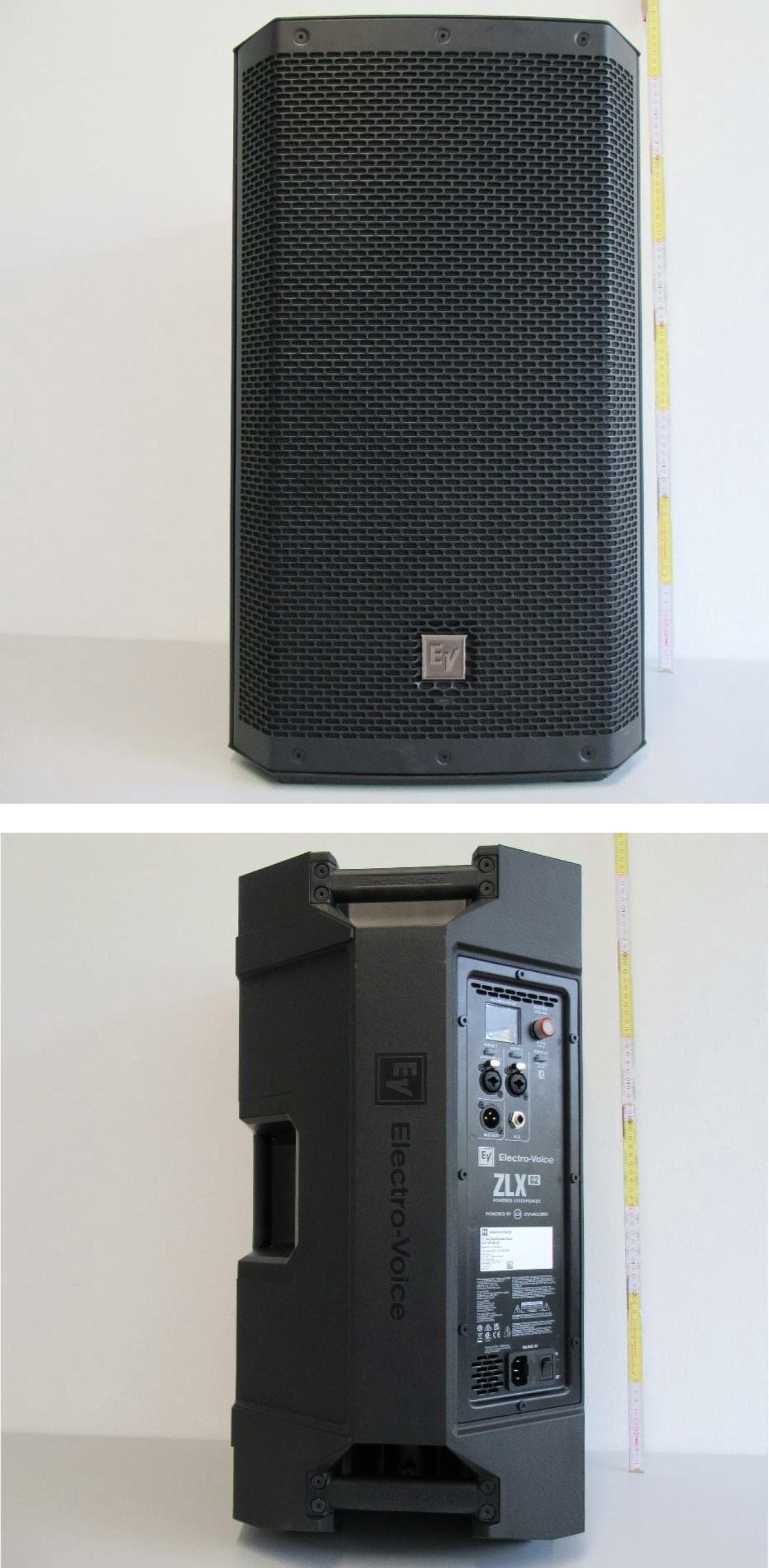
ESV-ZLXG2
Dec 21, 20232-way Powered Speaker
Equipment Class
DTS - Digital Transmission SystemESVD1
May 31, 2005Tritech Detector
Equipment Class
FDS - Part 15 Field Disturbance Sensor
ESV-RF3402
Dec 14, 2004Recessed Wireless Window or Door Magnetic Contact
Equipment Class
DSC - Part 15 Security/Remote Control Transmitter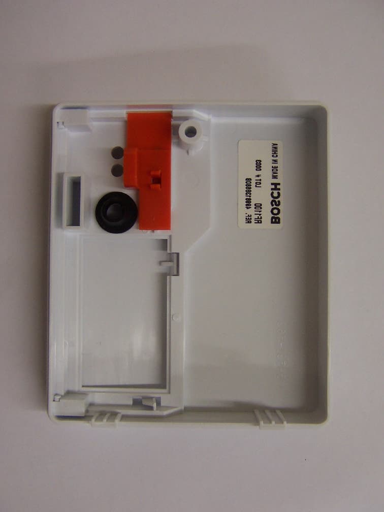
ESV-RF1100
Aug 04, 2004Wireless Glass Break Transmitter
Equipment Class
DSC - Part 15 Security/Remote Control Transmitter
ESV850
Oct 26, 2003PIR/Microwave Intrusion Detector
Equipment Class
FDS - Part 15 Field Disturbance Sensor