ESV-RF1100Wireless Glass Break Transmitter
Bosch Security Systems LLC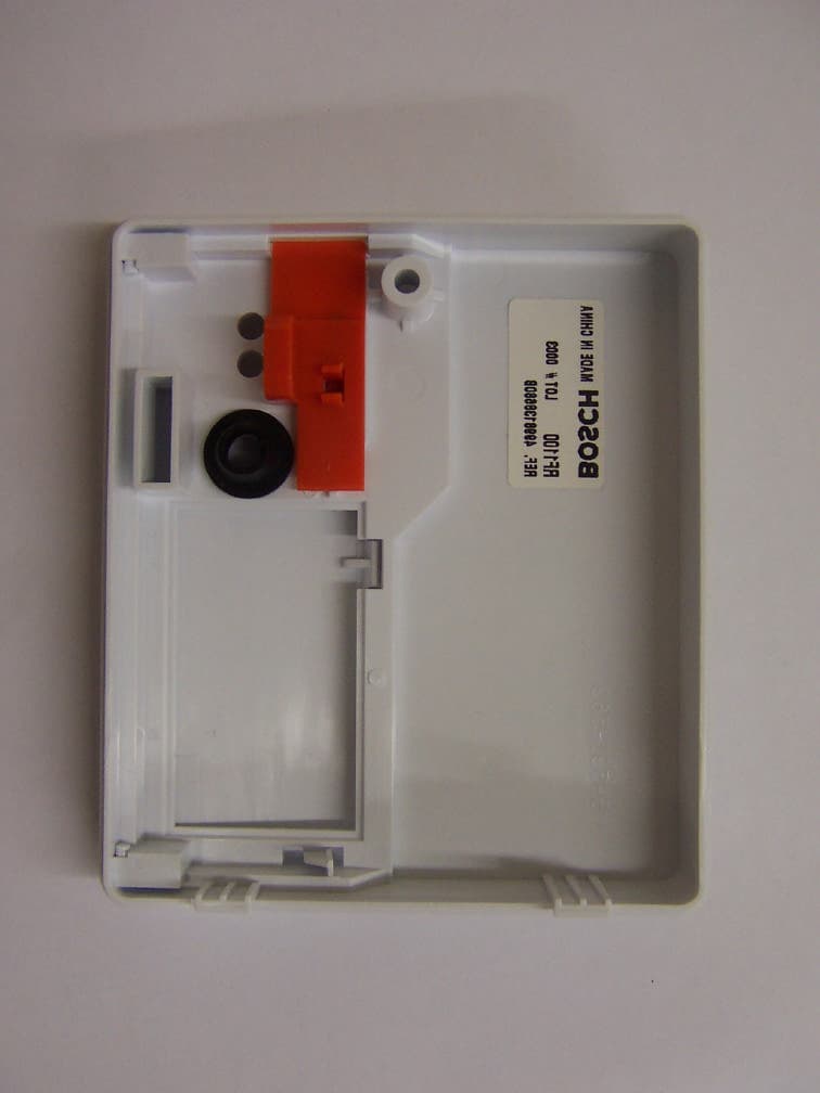
Click to zoom
Application Details
- Equipment Class
- DSC - Part 15 Security/Remote Control Transmitter
- Date of Grant
- Aug 04, 2004
- Application Purpose
- Original Equipment
- Date of Application
- Aug 04, 2004
- Equipment Note
- Wireless Glass Break Transmitter
- Frequency Range
- 304.00000000 - 304.00000000
- Company
- Bosch Security Systems LLC
- Country
- United States
Documents & Files
Document Text
Text extracted from the exhibit documents filed with the FCC. Open a document above to read the original.
Users Manual
EN Installation Instructions Wireless Glass Break Transmitter RF1100 RF1100 | Installation Instructions | Trademarks 2 Bosch Security Systems | 7/04 | 4998138680B Trademarks Duracell ® is a registered trademark of The Gillette Company. Eveready™ is a trademark of Eveready Battery Company, Inc. Panasonic ® is a registered trademark of Matsushita Electric Industrial Co., Ltd. Figure 1: RF1100 Mounting Template (Actual size) 3 22 1 1 - Wall tamper screw (optional) 2 - Mounting screw 3 - Base of RF1100 RF1100 | Installation Instructions | 1.0 Installation Considerations . Bosch Security Systems | 7/04 | 4998138680B 3 1.0 Installation Considerations Mount the RF1100 on flat surfaces such as ceilings and walls. Mount the unit to optimize glass break detection. Refer to Figure 2 and Figure 3 for mounting examples. In normal residential or commercial applications, locate the RF1100 within 325 ft (100 m) of its assigned receiver. For best detector performance, select a mounting location that is: • within 25 ft (7.6 m) of the protected glass • within clear view of the protected glass (there is no minimum range) • at least 6.5 ft (2 m) from the floor • at least 3.3 ft (1 m) from forced-air ducts • at least 3.3 ft (1 m) from sirens or bells (greater than 2 in. [5 cm] in diameter) • mounted on a window frame if any heavy window covering is present Avoid mounting the detector: • in a corner • on the same wall as the protected glass • on free-standing posts or pillars • in rooms with noisy equipment such as air compressors, bells, and power tools Test the detector in the desired mounting location before drilling mounting holes. Refer to Section 2.2 Testing on page 5. The RF1100’s maximum outside RF range is approximately 1000 ft (300 m). Figure 2: Wall Mounting Locations (top view) 7 5 1 2 4 3 6 3 3 1 - Poor location - fully opened door can block detector’s range 3 2 - Poor location - high risk of door slam noise 3 3 - 25 ft (7.6 m) maximum mounting distance 4 - Window 5 - Best locations 1 6 - Satisfactory location 2 7 - Satisfactory location if a heavy window covering is present 2 Figure 3: Ceiling Mounting Locations (side view) 1 4 3 5 2 1 - Best locations 1 2 - Ceiling 3 - 25 ft (7.6 m) maximum mounting distance 4 - Glass 5 - Floor 1 Best location: where the RF1100 is most effective. 2 Satisfactory location: where the effectiveness of the RF1100 can be reduced. 3 Poor location: where the effectiveness of the RF1100 is impaired. RF1100 | Installation Instructions | 2.0 Setup 4 Bosch Security Systems | 7/04 | 4998138680B 2.0 Setup 1. Carefully open the service door (Item 3 in Figure 4) and insert the two AA batteries (supplied), observing the correct polarity. 2. Select a mounting location (refer to Section 1.0 Installation Considerations on page 3). 3. Temporarily mount the unit so you can remove it as needed. 2.1 Sensitivity Setting 1. If the front housing is attached, carefully open the service door (Item 4 in Figure 5). 2. Enable the LEDs for test purposes by sliding the LED ENABLE switch (Item 5 in Figure 5) in the direction the arrow points (above the switch). An orange flag protrudes from the side of the RF1100. Figure 4: RF1100 Front Layout 8 9 3 5 7 6 1 EVENT 4 2 1 - Service door tamper switch 2 - AA batteries 3 - Service door 4 - SW4 Test Mode pads 5 - SW3 sensitivity DIP switches 6 - Alarm LED 7 - Event LED 8 - LED enable switch (off position) 9 - Housing screw Figure 5: Sensitivity Switch EVENT 3 2 4 5 1 1 - SENS2 2 - Test Mode pads 3 - SENS1 4 - Service door 5 - LED enable switch (shown in the OFF position) 3. Determine the sensitivity setting for your application from Table 1. Table 1: RF1100 Sensitivity Settings Sensitivity SENS1 SENS2 Approximate Range Maximum OFF OFF 25 ft (7.6 m) Medium ON OFF 15 ft (4.6 m) Low OFF ON 10 ft (3 m) Lowest ON ON 5 ft (1.5 m) 4. Use a small flat head screwdriver to move the sensitivity switches. Use the settings determined in Step 3. 5. Turn on any sources of noise such as machinery, office, or audio equipment in the area. 6. Observe the green event LED (Item 7 in Figure 4) for approximately 1 min. If the green LED flashes, relocate the unit or reduce the sensitivity by adjusting the sensitivity switch. 7. Repeat Steps 3 through 6 until you achieve the best sensitivity level. 8. After setting the sensitivity, slide the LED enable switch (Item 5 in Figure 5) to the OFF position. RF1100 | Installation Instructions | 2.0 Setup . Bosch Security Systems | 7/04 | 4998138680B 5 2.2 Testing Test the RF1100 at least once each year. Test the detector with the 13-332 Sound Sensor Tester. Figure 6: 13-332 Sound Sensor Tester 1 ACTIVATETESTFLEXMAN 234 1 - 13-332 2 - Activate/Test switch 3 - Start button 4 - Flex/Man switch 2.2.1 Entering Test Mode Place the RF1100 in Test Mode before testing the unit. Test Mode enables the RF1100's LED switch (Item 5 in Figure 5 on page 4). You can enter the Test Mode locally or remotely. To enter the Test Mode locally: 1. Carefully open the service door of the RF1100. 2. Insert a screwdriver into the slot next to the sensitivity switches that contains the test pads. 3. Touch both test pads at the same time with the tip of the screwdriver. The green LED (Item 7 in Figure 4 on page 4) on the RF1100 flashes once per second. If the green LED does not flash, repeat Steps 2 and 3. You can select the glass break sensitivity remotely from a Bosch 13-332 Sound Sensor Tester to activate a Test Mode. The 13-332 Sound Sensor Tester produces extremely loud sounds and can be hazardous to hearing when used at close range. Do not point the 13-332 towards someone’s head. To enter the Test Mode remotely: 1. Stand within 9 ft (3 m) of the RF1100. 2. Move the switches on top of the 13-332 tester to ACTIVATE (Item 2 in Figure 6) and MAN (Item 4, Figure 6) Modes. 3. Point the front of the tester towards the detector and press the red Start button (Item 3 in Figure 6). The tester buzzes and the green LED on the RF1100 flashes once per second. If the green…
Text truncated - open the document above for the full version.
Block Diagram
MICROCONTROLLER Waken up by ASIC Communicate with ASIC Task Determination RF Transmission 800 KHz Resonator RF Oscillator RF Amplifier Interface Circuit RESET MODULATION POWER CONTROL I/O / Interupt Control Low BT Detect Timer Oscillator Detection Circuit RC Circuit MB1 ECR# DR AUTHDATESYMREVISION RECORD ACCEPTED DRAWINGB09/08/03LAL BOSCH Control Tamper Alarm 2 “AA” M n 0 2 Battery 3VDC Acoustic Transducer Door/ Cover Switch TRANSMITTER ADEMCO GLASSBREAK HOST DATE DRAWN: DRAWING TITLE SCALE BOSCH SECURITY SYSTEMS 130 PERINTON PARKWAY FAIRPORT, NEW YORK, 14450-9199 USA (585) 223 4060 FAX (585) 223 9180 PART NO. 4998138678B 09/08/03 BLOCK DIAGRAM RF1100 SHEET 1 OF 1 DRAWING NUMBER DRAWN BY: LAL APPR BY: A4998138678 Rev. B
Test Report
Retlif Testing Laboratories R Test Report No. R-10364-1 FCC ID: ESV-RF1100 APPLICANT Bosch Security Systems, Inc. 130 Perinton Parkway Fairport, NY 14450 MANUFACTURER Bosch Security Systems, Inc. 130 Perinton Parkway Fairport, NY 14450 TEST SPECIFICATION:FCC Rules and Regulations Part 15, Subpart C, Para. 15.231 TEST PROCEDURE:ANSI C63.4:2001 TEST SAMPLE DESCRIPTION BRANDNAME: Bosch Security Systems, Inc.MODEL: RF1100 TYPE: Pulsed Transmitter POWER REQUIREMENTS: 2 AA Batteries FREQUENCY OF OPERATION: 304 MHz TESTS PERFORMED Para. 15.231(a), Radiated Emissions, Fundamental and Harmonics Para. 15.231(b), Duty Cycle Determination Para. 15.231(c), Occupied Bandwidth REPORT OF MEASUREMENTS Applicant: Bosch Security Systems, Inc. Device:Pulsed Transmitter FCC ID: ESV-RF1100 Power Requirements: 2 AA Batteries Applicable Rule Section:Part 15, Subpart C, Section 15.231 Retlif Testing Laboratories R Test Report No. R-10364-1 FCC ID: ESV-RF1100 REPORT OF MEASUREMENTS (continued) TEST RESULTS 15.231 (a):This device is used as a Remote Control/Security device. 15.231 (a)(1) &The transmitter is automatically operated. 15.231 (a)(3):The transmitter does perform periodic transmissions at intervals greater than once per hour. 15.231 (b):The fundamental field strength did not exceed 5580 μV/M (Average) at a test distance of 3 meters. In addition, the requirements of section 15.35 for averaging pulsed emissions and for limiting peak emissions were met. The field strength of harmonic and spurious emissions did not exceed 558 μV/M (AVERAGE). DETERMINATION OF FIELD STRENGTH LIMITS The field strength limits shown below are found in Section 15.231. Frequency Limit F1=2603750=L1 Fo=304Lo F2=47012500=L2 The formula below was utilized to determine the limits: Limit = L1 + [(Fo-F1)(L2-L1)/(F2-F1)] Solving yields: Fundamental Limit= 5580 μV/M (AVERAGE) @ 3 Meters Harmonic Limit= 558 μV/M (AVERAGE) @ 3 Meters Retlif Testing Laboratories R Test Report No. R-10364-1 FCC ID: ESV-RF1100 DUTY CYCLE DETERMINATION The unit’s RF output was directly coupled to the input of the spectrum analyzer. The analyzer was set for a frequency span of 0Hz. The sweep time was then adjusted in order to display one full pulse train. The transmitter on time was then summed and compared to the time for one full cycle in order to obtain the duty cycle. (See plots for additional information) Transmitter On Time=7.4 milliseconds (maximum) Transmitter Cycle Time=213 milliseconds Transmitter Duty Cycle=7.4 % CALCULATION: Duty Cycle (7.4/100)=7.4 % Correction Factor = 20 log(0.074)=-22.6 dB Retlif Testing Laboratories R Test Report No. R-10364-1 FCC ID: ESV-RF1100 SPECTRUM ANALYZER DESENSITIZATION CONSIDERATIONS Due to the nature of the emissions being measured, care was taken to ensure that the resolution bandwidth of the spectrum analyzer was adequate to provide accurate measurements. The following formula was utilized: Setting pulse desensitization equal to zero and utilizing the minimum observed pulse width of 200 μs yields a minimum required bandwidth of 3333 Hz. FCC specified bandwidths of 100 kHz and 1MHz were utilized below and above 1GHz, respectively. GENERAL NOTES 1.All readings were taken utilizing a peak detector function at a test distance of 3 meters. 2.The duty cycle was applied to the peak readings in order to determine the average value of the emissions. 3.The frequency range was scanned from 30 MHz to 3.1 GHz. All emissions not reported were more than 20 dB below the specified limit. Retlif Testing Laboratories R Test Report No. R-10364-1 FCC ID: ESV-RF1100 Equipment List RE Fundamental and Harmonics ENTypeManufacturerDescriptionModel No.Cal DateDue 067Open Area Test SiteRetlif3 MeterRNY10/1/200310/1/2006 128Double Ridged GuideElectro-Mechanics1 GHz - 18 GHz31056/13/20046/21/2005 133Broadband Pre-AmplifierElectro-Metrics10 kHz - 1 GHz, 26dBBPA-10006/21/20046/12/2005 141Spectrum AnalyzerHewlett Packard100 Hz - 40 GHz8566B½6/20047/26/2004 543PreamplifierHewlett Packard1.0 GHz - 26.5 GHz8449B7/24/20037/24/2004 617Interference AnalyzerElectro-Metrics10 kHz - 1 GHzEMC-309/30/20039/30/2004 712ACableRetlif10 kHz - 18 GHzR&S Analyzer7/9/20037/9/2004 723H.P. FilterMini-Circuits1 GHzBHP-10007/11/20037/11/2004 206B6.0 dB AttenuatorTexscan0 - 1.0 GHzFP-50 - 6 dB6/12/20046/12/2005 Retlif Testing Laboratories R Test Report No. R-10364-1 FCC ID: ESV-RF1100 FCC 15.231(b) RADIATED EMISSIONS, FUNDAMENTAL (See separate e-file named Refundharm.pdf) Retlif Testing Laboratories R Test Report No. R-10364-1 FCC ID: ESV-RF1100 FCC 15.231(c) OCCUPIED BANDWIDTH (See separate e-file named occbw.pdf) Retlif Testing Laboratories R Test Report No. R-10364-1 FCC ID: ESV-RF1100 FCC 15.231(c) DUTY CYCLE (See separate e-file named dutycycle.pdf) Retlif Testing Laboratories R Test Report No. R-10364-1 FCC ID: ESV-RF1100 Test Setup Photograph
Test Setup Photos
Retlif Testing Laboratories R Test Report No. R-10364-1 FCC ID: ESV-RF1100 Test Setup Photograph
Contact Information
Applicant
Peter Namisnak(Sr. Regulatory Compliance Coordinator)
Technical Contact
Retlif Testing LaboratoriesThomas Schneider
[email protected]631-737-1500
795 Marconi Ave · Ronkonkoma, New York · United States
Non-Technical Contact
Retlif Testing LaboratoriesMichelle White
[email protected]631-737-1500
Test Firm
Retlif Testing LaboratoriesMichael Bozza
Technical Specifications
| # | Rule Parts | Frequency Range | Power Output |
|---|---|---|---|
| 1 | 15.231 | 304 MHz - 304 MHz | - |
Other Applications from Bosch Security Systems LLC
ESV-ZLXG2
Dec 21, 20232-way Powered Speaker
Equipment Class
DTS - Digital Transmission SystemESVD1
May 31, 2005Tritech Detector
Equipment Class
FDS - Part 15 Field Disturbance Sensor
ESV-RF3402
Dec 14, 2004Recessed Wireless Window or Door Magnetic Contact
Equipment Class
DSC - Part 15 Security/Remote Control Transmitter
ESV850
Oct 26, 2003PIR/Microwave Intrusion Detector
Equipment Class
FDS - Part 15 Field Disturbance Sensor
ESV840LSN
Oct 26, 2003Dual Mode Field Disturbance Sensor
Equipment Class
FDS - Part 15 Field Disturbance Sensor