ESV-0117-4Security Escort Transmitter
Bosch Security Systems LLC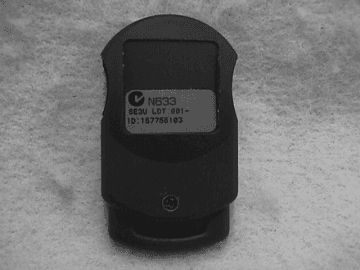
Click to zoom
Application Details
- Equipment Class
- DSC - Part 15 Security/Remote Control Transmitter
- Date of Grant
- Oct 14, 1999
- Application Purpose
- Original Equipment
- Date of Application
- Sep 20, 1999
- Equipment Note
- Security Escort Transmitter
- Frequency Range
- 304.00000000 - 304.00000000
- Company
- Bosch Security Systems LLC
- Country
- United States
Documents & Files
Document Text
Text extracted from the exhibit documents filed with the FCC. Open a document above to read the original.
Users Manual
Copyright © 1997 - 1998 Detection Systems, Inc. SE3/SE4 Transmitters User’s Guide PN 36447C 9/98 Introduction The SE3 and SE4 are personal transmitters designed to work with the Security Escort System. When initiated, a signal identifying you and your location is sent to the security office. The SE3 and SE4 may also be tested within sight of a Receiver or Siren/Strobe by the user. The SE3 and SE4 are available in two models: User (U) model and Security (S) model. The User model is the standard model; the Security model has the same features as the User model, except that the transmitter will not make an audible tone when transmitting an alarm. User’s Guide for the SE3/SE4 Security Escort Transmitters The Security Escort system is NOT a substi- tute for safe behavior. System users should not take personal risks under the misconcep- tion that the system will provide protection that will compensate for taking such risks. Figure 2. Siren/Strobe and Receiver Figure 1. Transmitting an Alarm Transmitting an Alarm Use your transmitter to transmit an alarm only when you are in danger, seriously injured, or feel threatened. NOTE:Your personal transmitter is an emergency communica- tion device and should not be used for routine commu- nications with security officials. Transmitting an alarm alerts a computer located in the security office that you require emergency assistance. A display on the computer screen indicates your identity and approximate location, and an officer is dispatched to assist you. In some facilities, flashing strobes and audible sirens will be activated in the vicinity of your location. To transmit an alarm: •Hold the transmitter away from your body. •Press both buttons together and hold! In a vehicle, hold the transmitter close to a window when transmit- ting. NOTE:You do not have to point the transmitter at a Receiver, nor do you need to be in sight of a Receiver to activate an alarm. Testing the Transmitter Test the transmitter weekly. To verify the transmitter’s operation: 1.Stand in sight of a Security Escort Siren/Strobe or a Security Escort Receiver. Receivers are located inside buildings usually within sight of an exit door. They are mounted on walls in light beige, rectangular enclo- sures bearing the Security Escort logo. Siren/Strobes are typically mounted on outside building walls and on light poles. 2.Press either button on your Security Escort Transmitter for about one second until you hear a tone. Release. Then press the other button for about one second until you hear a tone. Do not hold both buttons down at the same time as this will generate an alarm. 3.Look for a flashing strobe on a Siren/Strobe or a flashing green light on a Receiver. A flashing green light on a Receiver or a flashing strobe on an Siren/ Strobe confirms that the entire system is working. If you do not see the flashing light or flashing strobe, the test was not successful. NOTE:There might be a brief delay of two or three seconds before the flashing light appears. If there is no response, try the test again. If there is no response the second time, your transmitter might not be working. Take the transmitter to the security office. Figure 3. Testing the Transmitter DO NOT HESITATE TO RETRANSMIT. The system will update your location each time you retransmit an alarm. Once initiated, the transmitter will send a signal every few seconds updating your location until a test is performed. PN 36447C 9/98SE3/SE4 Transmitters User’s GuideCopyright © 1997 - 1998 Detection Systems, Inc. Page 2 Important Information for all Users of the Security Escort System Protected Areas Check with the security department to verify the exact areas of the facility that are protected by the system and those that are not. Use of Transmitter by Others Your personal transmitter is assigned specifically to you and is for your use only. It should not be transferred, loaned, or shared with another individual. Before letting anyone handle your transmitter, be sure to inform them that it is an emergency communication device that, when activated, transmits your identity. An officer will be dis- patched to the location of the transmitter when it is activated. Lost or Stolen Transmitters In the event your transmitter is lost or stolen, report the incident immediately to the security office so that a replacement can be issued to you and the original transmitter can be deleted from the system. Tips for Better Transmission As with all radio equipment, the signal strength from your Security Escort Personal Transmitter will be reduced by metal and wet surfaces, and to some extent by the human body. To ensure proper transmission of an alarm, hold the transmitter in one hand, away from your body and other objects, press both buttons together and hold. In a vehicle, hold the transmitter close to a window when transmitting. Do not hesitate to retransmit. Battery Life Assuming normal usage (such as weekly testing), the battery will last approximately four years. If the battery is weak, a special signal is sent to the security office during a test. Tests will not produce a flashing light on a Receiver or Siren/Strobe when your transmitter has a weak battery. Exposure to Moisture The transmitter is designed to be water resistant, and chances are it will not be affected by moisture. Neverthe- less, you should test your transmitter a few times (several hours apart) after it has been exposed to moisture to verify it is working properly. Accidental Alarms If you accidentally set off an alarm, STAY WHERE YOU ARE! Wait for the security official who responds to your alarm. Explain that you inadvertently set off your transmitter and make it clear that you are not experiencing an emergency. FCC Statement This device complies with Part 15 of the FCC Rules and with RSS-210 of Industry and Science Canada. Operation is subject to the following two conditions: (1) this device may not cause harmful interference, and (2) this device must accept any interfer…
Text truncated - open the document above for the full version.
Block Diagram
SAN ECR# DR AUTHDATESYMREVISION RECORD ACCEPTED DRAWINGB9/9/99DM DATE DRAWN DRAWING NUMBER DRAWING TITLE DRAWN BY: SAN APPR BY: SCALE A42409REV-B ds ® SHEET 1 OF 1 DETECTION SYSTEMS, INC. BLOCK DIAGRAM - SE3 FAMILY 130 PERINTON PARKWAY FAIRPORT, NEW YORK, 14450-9099, USA (716) 223 4060, FAX (716) 223 9180 9/9/99 PART NO. 42409B PROPRIETARY DATA DATA CONTAINED HEREIN SHALL NOT BE USED, DUPLICATED OR DISCLOSED IN WHOLE OR PART OUTSIDE DETECTIONS SYSTEMS INC. WITHOUT EXPRESSED WRITTEN PERMISSION OF SAME. MicroController performs duties of RF transmissions: alarms, tests, supervisories, autotracking. DATA bits include the status of inputs and battery level. temperature compensated, low battery detection circuitry 2 BATTERIES 6 volt lithium microcontroller power latching circuit Button 2 antenna Button 1 PIEZO sounder RF amplifier on/off power level RF oscillator
Operational Description
Se3x_304 tech desc.doc SE3x-304 Technical Description 7-SEPT-99 SE3x family are personal duress transmitters to be used in Security Escort systems. The unit also comes with a split key ring. Three(3) versions are available: • SE3U - 304 “USER” version is the main selling item. • SE3S - 304 “SECURITY” version has a silent piezo on alarm. • SE3M - 304 “MAINTAINENCE” version has no alarm and is only used for system verification and testing. The SE3x has two buttons that, when pressed simultaneously, sends duress transmission to the system and then starts “auto-track” mode which transmits in 15 second intervals for a fifteen(15) minute duration, and can be canceled by a “Test”. A test signal can be sent to ensure that the unit and the system are operating properly. To send a test signal, one button is pressed, released and the other button is pressed and released. A beep exists after each button press. The transmitter contains replaceable, 3 volt lithium coin cells. The SE3x-304 models are compatible with 304 MHz receivers and follow the Detection Systems 5kbps RF protocol. Center frequency is 304 MHz controlled by a SAW oscillator. The system uses ON/OFF keyed AM for the transmission format.
Parts List/Tune Up Info
SHOW.PS Fairport Multi-Level Bills of Material 09:40:30 04 AUG 1999 Requested by engineer Page 1Level/Part E Description Qty/Assy UM IT Rt Scr PBT Rv LT RTG ECO ECO Note Reference Designator S Nbr % HNP Lv Off Seq Number Date Refer 0 SE3U-304 D TX SM CAMPUS-USER EA FG 1....... 39128 A ASM-SE3U-304 -MECH 1.00 EA SA 200 1 200 2...... 19301D A LBL-PRODUCT SHIPPING 1.00 EA PP 90 B1 902...... 25099B A HANDHELD PANIC BASE 1.00 EA PP 60 1 602...... 25100C A HANDHELD PANIC BUTTON 2.00 EA PP 60 1 602...... 29895B A DET-DS924i 25pc PARTITION 0.04 EA PP 90 1 902...... 29896B A BOX-PCB 16.06x12.12x2.13 0.04 EA PP 90 1 902...... 33890B A SWR-MS256X0.375PHP-STBLKO 1.00 EA PP 60 B1 602...... 35299B A BTRY- 3V- CR2025 LITHIUM 2.00 EA PP 60 1 602...... 35379B A DOUBLE,COIN CELL CONTACT 1.00 EA PP 60 1 60 B12...... 35561C A PURCH COVER ASM (SE3) 1.00 EA PP 60 1 60 3..... 25098D A HANDHELD PANIC COVER 1.00 EA PP 13..... 35563B A SECURITY ESCORT FILMTOOLS 0.00 EA PP 2 2...... 36447C A INGUIDE (SE3,4) 1.00 EA PP 90 1 902...... 38724B A KEY RING, 0.75 INCH 1.00 EA PP 90 1 902...... 39127 A ASM-SE3U-304 -PCSM 1.00 EA SA 50 1 50 3..... 16142 A CAP-CC- .01M- 50V-K-SMR 2.00 EA PP 20 1 20 3199 C1,C73..... 16143 A CAP-CC- 100P- 50V-K-SMR 1.00 EA PP 20 1 20 C133..... 19935 A DIO-RLS4153 -SI .1A 50VSM 3.00 EA PP 20 1 20 D2,D3,D43..... 20371 A DIZ-MZ4619 -J.25W 3.0VAR 1.00 EA PP 40 1 40 D13..... 20990 A TRA-5089 -NPN-SI- SM 3.00 EA PP 20 1 20 Q4,Q5,Q63..... 22653 A RES-TF-0.1W- 8.2K-J-SMR-N 1.00 EA PP 20 1 20 R53..... 22654 A RES-TF-0.1W- 10K-J-SMR-N 3.00 EA PP 20 1 20 R13,R14,R153..... 22656 A RES-TF-0.1W- 15K-J-SMR-N 1.00 EA PP 20 1 20 R103..... 22663 A RES-TF-0.1W- 56K-J-SMR-N 4.00 EA PP 20 1 20 R16,R17,R18,R203..... 22664 A RES-TF-0.1W- 68K-J-SMR-N 2.00 EA PP 20 1 20 R4,R223..... 22666 A RES-TF-0.1W- 100K-J-SMR-N 3.00 EA PP 20 1 20 R9,R11,R123..... 22668 A RES-TF-0.1W- 150K-J-SMR-N 1.00 EA PP 20 1 20 R13..... 22670 A RES-TF-0.1W- 220K-J-SMR-N 1.00 EA PP 20 1 20 R243..... 22678 A RES-TF-0.1W- 1M-J-SMR-N 2.00 EA PP 20 1 20 3229 R8,R193..... 23481 A TRA-MMBT4403-PNP-SI-SS-SM 1.00 EA PP 20 1 20 Q13..... 23532B A CAP-CC- 2.2P- 50V-C-SMR 1.00 EA PP 20 1 20 C123..... 24462B A TRA-MMBT5087L-PNP-SI 1.00 EA PP 20 1 20 Q33..... 24738B A CAP-CC- 12P- 50V-J-SMR 3.00 EA PP 20 1 20 C6,C10,C113..... 25040B A RES-TF-0.1W- 10 -J-SMR-N 1.00 EA PP 20 1 20 R233..... 25041B A RES-TF-0.1W- 47 -J-SMR-N 2.00 EA PP 20 1 20 R6,R73..... 25045B A RES-TF-0.1W- 330 -J-SMR-N 1.00 EA PP 20 1 20 R23..... 25049B A RES-TF-0.1W- 820 -J-SMR-N 1.00 EA PP 20 1 20 R33..... 25434C A CAP-CC- 470P- 50V-J-SMR 3.00 EA PP 20 1 20 C2,C4,C53..... 26714B A CAP-CC- 18P- 50V-J-SM 1.00 EA PP 20 1 20 C83..... 27140B A CAP-TA- 4.7M- 16V-K-SMR 1.00 EA PP 20 1 20 C33..... 27787B A THERM- 30K NTC-20%-SMR 1.00 EA PP 20 1 20 RT13..... 27896B A COIL-82nH-10% 1.00 EA PP 20 1 20 L23..... 27897B A COIL-68NH 1.00 EA PP 20 1 20 L33..... 28350B I COIL-12nH-20% 1.00 EA PP 20 1 20 L43..... 31062B A CAP-CC- 2.7P- 50V-C-SMR 2.00 EA PP 20 1 20 C9,C143..... 33090B A TRA-MMBR911LT1-NPN-SI-RF 1.00 EA PP 20 1 20 Q73..... 34169B A TRA-MMBTH10 -NPN-SI-RF 1.00 EA PP 20 1 20 Q23..... 34703B A TERM.COIN CELL,NEG,PC,SE3 1.00 EA PP 40 1 40 B23..... 35675B A PIEZO ALARM (13mm) 1.00 EA PP 40 1 40 DS13..... 35954B A COIL-47nH-10% 1.00 EA PP 20 1 20 L13..... 36713B A RES-TF-.1W-2.2K-J-SMR 1.00 EA PP 20 1 20 R213..... 37043B A RESONATOR 304.000MHZ SM 1.00 EA PP 20 1 20 Y13..... 38725D E SCHEMATIC (SE3) 0.00 EA DR 40 1 40 31993..... 38726C I P.C. BOARD (SE3) 1.00 EA PP 20 1 203..... 39129B A PGMD IC-SE3U-304 -V1.01 1.00 EA PA 20 1 20 3199 U1 4.... 39130B A EXEC CODE-SE3U-304 -V1.01 0.00 EA DR 24.... 41614B A IC(PIC12C508A-04I) UNPROG 1.00 EA PP 2 3..... 41097B A SW-PUSH-SPST-MOM/RT ANGLE 2.00 EA PP 40 1 40 S1,S23..... 41793B A RES-TF-0.1W- 1M-22678 1.00 EA MP 40 1 40 3229 R25 4.... 22678 A RES-TF-0.1W- 1M-J-SMR-N 1.00 EA PP 1 2...... 39135B A LBL- SE3U-304 1.00 EA PP 90 1 90 3202 LBL1
Test Report
Test Report No. R-8176-1 FCC ID: ESV-0117-4 APPLICANT Detection Systems 130 Perinton Parkway Fairport, NY 14450 MANUFACTURER Same As Applicant TEST SPECIFICATION: FCC Rules and Regulations Part 15, Subpart C, Para. 15.231 TEST PROCEDURE: ANSI C63.4:1992 TEST SAMPLE DESCRIPTION BRANDNAME: Detection Systems MODEL: SE3U-304 TYPE: 304 MHz Pulsed RF Transmitter POWER REQUIREMENTS: 6 VDC derived from (2) CR2025 Lithium Batteries FREQUENCY OF OPERATION: 304 MHz TESTS PERFORMED Para. 15.231(a), Radiated Emissions, Fundamental and Harmonics Para. 15.231(c), Occupied Bandwidth Duty Cycle Determination REPORT OF MEASUREMENTS Applicant: Detection Systems Device:304 MHz Pulsed RF Transmitter FCC ID: ESV-0117-4 Power Requirements: 6 VDC derived from (2) CR2025 Lithium Batteries Applicable Rule Section:Part 15, Subpart C, Section 15.231 Test Report No. R-8176-1 FCC ID: ESV-0117-4 REPORT OF MEASUREMENTS (continued) TEST RESULTS 15.231 (a) -The device is used as a transmitter for security purposes. 15.231 (a)(1) & -The transmitter is manually operated and ceases transmission within 5 15.231(2)seconds after activation. 15.231 (a)(3) -The transmitter does not perform periodic transmissions. 15.231 (a)(4)-The device is employed for RC purposes involving security. 15.231 (b) -The fundamental field strength did not exceed 5580 μV/M (Average) at a test distance of 3 meters. In addition, the requirements of section 15.35 for averaging pulsed emissions and for limiting peak emissions were met. The field strength of harmonic and spurious emissions did not exceed 558 μV/M (AVERAGE). 15.231 (c) -The device operates at 304 MHz. The bandwidth of emissions did not exceed 0.25% of the operating frequency (760 kHz). DETERMINATION OF FIELD STRENGTH LIMITS The field strength limits shown below are found in Section 15.231. Frequency Limit F1=2603750 =L1 Fo=304Lo F2=47012500 =L2 The formula below was utilized to determine the limits: Limit = L1 + [(Fo-F1)(L2-L1)/(F2-F1)] Solving yields: Fundamental Limit= 5,580 μV/M (AVERAGE) @ 3 Meters Harmonic Limit= 558 μV/M (AVERAGE) @ 3 Meters Test Report No. R-8176-1 FCC ID: ESV-0117-4 REPORT OF MEASUREMENTS (continued) DETERMINATION OF DUTY CYCLE AS PER DETECTION SYSTEMS: Each packet contains 76 data bits and the packet transmission time with 5 kHz data rate is 15.2 milliseconds. The 50% duty cycle Manchester coding of the transmission ensures a 50% ON- AIR time for every packet which is 7.6 milliseconds. The minimum quiet time between packets is 100 milliseconds. Packet Time = 15.2 milliseconds Quiet Time between Packets = 100 milliseconds ON-AIR Time = (Packet Time) x 50% = 7.6 milliseconds, in 115.2 milliseconds Factor = 20 Log (ON-AIR Time/100 milliseconds) = 20 Log (0.076) = -22.4dB SPECTRUM ANALYZER DESENSITIZATION CONSIDERATIONS Due to the nature of the emissions being measured, care was taken to ensure that the resolution bandwidth of the spectrum analyzer was adequate to provide accurate measurements. The following formula was utilized: Setting pulse desensitization equal to zero and utilizing the minimum observed pulse width of 100μs yields a minimum required bandwidth of 6666.66 Hz. FCC specified bandwidths of 100kHz and 1MHz were utilized below and above 1GHz, respectively. Test Report No. R-8176-1 FCC ID: ESV-0117-4 REPORT OF MEASUREMENTS (continued) GENERAL NOTES 1. All readings were taken utilizing a peak detector function at a test distance of 3 meters. 2. The duty cycle was applied to the peak readings in order to determine the average value of the emissions. 3. All measurements were made with (2) new 3 VDC, CR2025 Lithium Batteries. 4. The frequency range was scanned from 30 MHz to 3.1 GHz. All emissions not reported were more than 20 dB below the specified limit. Test Report No. R-8176-1 FCC ID: ESV-0117-4 EQUIPMENT LIST FCC Part 15, Subpart C ENTypeManufacturerFrequency Range Model No.Cal Date Due Date 067Open Area Test SiteRetlif3 MeterRNY8/30/978/30/99 128CDouble Ridge GuideEaton Corporation1 GHz - 18 GHz9600110/6/9810/6/99 133Broadband Pre-AmplifierElectro-Metrics10 kHz - 1 GHz, 26dBBPA-10006/22/996/22/00 141Spectrum AnalyzerHewlett Packard100 Hz - 40 GHz8566B3/16/999/16/99 141AGraphics PlotterHewlett PackardN/A7470A3/5/993/5/00 141BQuasi-Peak AdaptorHewlett Packard100 Hz - 1 GHz85650A3/16/999/16/99 206B6.0 dB AttenuatorTexscan0 - 1.0 GHzFP-50 - 6 dB6/22/996/22/00 523BiconilogElectro-Mechanics26 - 2000 MHz3142B10/22/984/22/00 543PreamplifierHewlett Packard1.0 GHz - 26.5 GHz8449B6/16/996/16/01 Test Report No. R-8176-1 FCC ID: ESV-0117-4 FCC 15.231(a) RADIATED EMISSIONS, FUNDAMENTAL & HARMONICS (See separate e-file attachment named REdata.doc) Test Report No. R-8176-1 FCC ID: ESV-0117-4 FCC 15.231(c) OCCUPIED BANDWIDTH (See separate e-file attachments named occbw1.pdf and occbw2.pdf)
Test Report
Test Method: FCC Part 15 Subpart C Radiated Emissions Paragraph 15.231 Customer: Detection Systems Job No. R-8176 Test Sample: 304 Mhz RF Transmitter FCC ID: ESV-0117-4 Model No.: SE3U-304 Serial No. N/A Operating Mode: Pulsing at 304 Mhz Technician: Dennis Cortes Date: July 27,1999 Notes: Test Distance: 3 Meters Detector: Peak Test Freq. Antenna Pol./Height EUT Orientation Meter Reading Correction Factor Corrected Reading Converted Reading Peak Limit Mhz(V/H) / MetersX / Y / Z dBuv dB dBuV/m uV/m uV/m 304.0H / 2.1X90.7-4.286.521134.955800 304.0H / 1.0Y95.0-4.290.834673.755800 304.0H / 1.0Z95.7-4.291.537583.755800 304.0V / 1.9X92.4-4.288.225704.055800 304.0V / 1.0Y80.4-4.276.26456.555800 304.0V / 1.2Z80.1-4.275.96237.355800 608.0H / 1.8X47.52.750.2323.62000 608.0H / 1.0Y50.82.753.5473.22000 608.0H / 1.0Z53.32.756.0631.02000 608.0V / 1.6X51.52.754.2512.92000 608.0V / 1.4Y46.82.749.5298.52000 608.0V / 1.0Z47.32.750.0316.22000 912.0H / 1.2X43.57.250.7342.85580 912.0H / 1.2Y40.97.248.1254.15580 912.0H / 1.1Z44.87.252.0398.15580 912.0V / 1.1X44.07.251.2363.15580 912.0V / 1.0Y43.67.250.8346.75580 912.0V / 1.1Z46.97.254.1507.05580 1216.0H / 1.4X52.6-4.048.6269.25000 1216.0H / 1.0Y51.5-4.047.5237.15000 1216.0H / 1.0Z51.7-4.047.7242.75000 1216.0V / 1.0X55.9-4.051.9393.65000 1216.0V / 1.1Y56.4-4.052.4416.95000 1216.0V / 1.0Z56.0-4.052.0398.15000 1520.0H / 1.3X58.1-0.857.3732.85000 1520.0H / 1.5Y55.9-0.855.1568.95000 1520.0H / 1.0Z55.4-0.854.6537.05000 1520.0V / 1.2X57.1-0.856.3653.15000 1520.0V / 1.0Y56.7-0.855.9623.75000 1520.0V / 1.0Z55.5-0.854.7543.35000 The frequency range was scanned from 30 Mhz to 3.1 Ghz. The emissions observed from the EUT do not exceed the specified limit. All emissions not recorded were more than 20 dB below the specified limit Data sheet 1 of 4 Test Method: FCC Part 15 Subpart C Radiated Emissions Paragraph 15.231 Customer: Detection Systems Job No. R-8176 Test Sample: 304 Mhz RF Transmitter FCC ID: ESV-0117-4 Model No.: SE3U-304 Serial No. N/A Operating Mode: Pulsing at 304 Mhz Technician: Dennis Cortes Date: July 27,1999 Notes: Test Distance: 3 Meters Detector: Peak Test Freq. Antenna Pol./Height EUT Orientation Meter Reading Correction Factor Corrected Reading Converted Reading Peak Limit Mhz(V/H) / MeterssX / Y / Z dBuv dB dBuV/m UV/m uV/m 1824H / 1.3X49.01.650.6338.85580 1824H / 1.3Y51.91.653.5473.25580 1824H / 1.1Z50.51.652.1402.75580 1824V / 1.0X50.91.652.5421.75580 1824V / 1.0Y50.51.652.1402.75580 1824V / 1.0Z50.51.652.1402.75580 2128H / 1.2X51.7-1.350.4331.15580 2128H / 1.5Y49.2-1.347.9248.35580 2128H / 1.1Z49.9-1.348.6269.25580 2128V / 1.3X50.2-1.348.9278.65580 2128V / 1.3Y50.5-1.349.2288.45580 2128V / 1.0Z48.3-1.347.0223.95580 2432H /1.2X50.2-0.449.8309.05580 2432H / 1.0Y54.5-0.454.1507.05580 2432H / 1.1Z51.4-0.451.0354.85580 2432V / 1.2X54.8-0.454.4524.85580 2432V / 1.4Y48.9-0.448.5266.15580 2432V / 1.3Z53.7-0.453.3462.45580 2736H / 1.6X45.01.146.1201.85000 2736H / 1.0Y47.51.148.6269.25000 2736H / 1.6Z45.31.146.4208.95000 2736V / 1.0X47.81.148.9278.65000 2736V / 1.1Y46.01.147.1226.55000 2736V / 1.2Z49.11.150.2323.65000 3040H / 1.0X48.53.151.6380.25580 3040H / 1.3Y45.13.148.2257.05580 3040H / 1.3Z45.63.148.7272.35580 3040V / 1.0X43.83.146.9221.35580 3040V / 1.0Y46.23.149.3291.75580 3040V / 1.0Z46.63.149.7305.55580 The frequency range was scanned from 30 Mhz to 3.1 Ghz. The emissions observed from the EUT do not exceed the specified limit. All emissions not recorded were more than 20 dB below the specified limit Data sheet 2 of 4 Test Method: FCC Part 15 Subpart C Radiated Emissions Paragraph 15.231 Customer: Detection Systems Job No. R-8176 Test Sample: 304 Mhz RF Transmitter FCC ID: ESV-0117-4 Model No.: SE3U-304 Serial No. N/A Operating Mode: Pulsing at 304 Mhz Technician: Dennis Cortes Date: July 27,1999 Notes: Test Distance: 3 Meters Duty Cycle: 7.6% Detector: Peak Duty Cycle Correction: -22 4dB Test Freq. Antenna Pol./Height EUT Orientation Peak Reading Correction Factor Corrected Reading Converted Reading Average Limit Mhz(V/H) / MetersX / Y / Z dBuv dB dBuV/m uV/m uV/m 304.0H / 2.1X86.5-22.464.11603.25580 304.0H / 1.0Y90.8-22.468.42630.35580 304.0H / 1.0Z91.5-22.469.12851.05580 304.0V / 1.9X88.2-22.465.81949.85580 304.0V / 1.0Y76.2-22.453.8489.85580 304.0V / 1.2Z75.9-22.453.5473.25580 608.0H / 1.8X50.2-22.427.824.5200 608.0H / 1.0Y53.5-22.431.135.9200 608.0H / 1.0Z56.0-22.433.647.9200 608.0V / 1.6X54.2-22.431.838.9200 608.0V / 1.4Y49.5-22.427.122.6200 608.0V / 1.0Z50.0-22.427.624.0200 912.0H / 1.2X50.7-22.428.326.0558 912.0H / 1.2Y48.1-22.425.719.3558 912.0H / 1.1Z52.0-22.429.630.2558 912.0V / 1.1X51.2-22.428.827.5558 912.0V / 1.0Y50.8-22.428.426.3558 912.0V / 1.1Z54.1-22.431.738.5558 1216.0H / 1.4X48.6-22.426.220.4500 1216.0H / 1.0Y47.5-22.425.118.0500 1216.0H / 1.0Z47.7-22.425.318.4500 1216.0V / 1.0X51.9-22.429.529.9500 1216.0V / 1.1Y52.4-22.430.031.6500 1216.0V / 1.0Z52.0-22.429.630.2500 1520.0H / 1.3X57.3-22.434.955.6500 1520.0H / 1.5Y55.1-22.432.743.2500 1520.0H / 1.0Z54.6-22.432.240.7500 1520.0V / 1.2X56.3-22.433.949.5500 1520.0V / 1.0Y55.9-22.433.547.3500 1520.0V / 1.0Z54.7-22.432.341.2500 The frequency range was scanned from 30 Mhz to 3.1 Ghz. The emissions observed from the EUT do not exceed the specified limit. All emissions not recorded were more than 20 dB below the specified limit Data sheet 3 of 4 Test Method: FCC Part 15 Subpart C Radiated Emissions Paragraph 15.231 Customer: Detection Systems Job No. R-8176 Test Sample: 304 Mhz RF Transmitter FCC ID: ESV-0117-4 Model No.: SE3U-304 Serial No. N/A Operating Mode: Pulsing at 304 Mhz Technician: Dennis Cortes Date: July 27,1999 Notes: Test Distance: 3 Meters Duty Cycle: 7.6% Detector: Peak Duty Cycle Correction: -22.4dB Test Freq. Antenna Pol./Height EUT Orientation Peak Reading Correction Factor Corrected Reading Converted Reading Average Limit Mhz(V/H) / MetersX / Y / Z dBuv dB dBuV/m UV/m uV/m 1824H / 1.3X50.6-22.428.225.7558 1824H / 1.3Y53.5-22.431.135.9558 1824H / 1.1Z52.1-22.429.730.5…
Text truncated - open the document above for the full version.
Contact Information
Applicant
Peter Namisnak(Sr. Regulatory Compliance Coordinator)
Technical Contact
Retlif Testing LaboratoriesThomas J Schneider
[email protected]516-737-1500
795 Marconi Avenue · Ronkonkoma, New York · United States
Non-Technical Contact
Retlif Testing LaboratoriesMichelle Tirado
[email protected]516-737-1500
Test Firm
Retlif Testing LaboratoriesMichael Bozza
Technical Specifications
| # | Rule Parts | Frequency Range | Power Output |
|---|---|---|---|
| 1 | 15C | 304 MHz - 304 MHz | - |
Other Applications from Bosch Security Systems LLC
ESV-ZLXG2
Dec 21, 20232-way Powered Speaker
Equipment Class
DTS - Digital Transmission SystemESVD1
May 31, 2005Tritech Detector
Equipment Class
FDS - Part 15 Field Disturbance Sensor
ESV-RF3402
Dec 14, 2004Recessed Wireless Window or Door Magnetic Contact
Equipment Class
DSC - Part 15 Security/Remote Control Transmitter
ESV-RF1100
Aug 04, 2004Wireless Glass Break Transmitter
Equipment Class
DSC - Part 15 Security/Remote Control Transmitter
ESV850
Oct 26, 2003PIR/Microwave Intrusion Detector
Equipment Class
FDS - Part 15 Field Disturbance Sensor