ESV840LSNDual Mode Field Disturbance Sensor
Bosch Security Systems LLC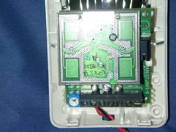
Click to zoom
Application Details
- Equipment Class
- FDS - Part 15 Field Disturbance Sensor
- Date of Grant
- Oct 26, 2003
- Application Purpose
- Original Equipment
- Date of Application
- Oct 26, 2003
- Equipment Note
- Dual Mode Field Disturbance Sensor
- Frequency Range
- 10525.00000000 - 10525.00000000
- Company
- Bosch Security Systems LLC
- Country
- United States
Documents & Files
Document Text
Text extracted from the exhibit documents filed with the FCC. Open a document above to read the original.
Users Manual
EN Installation Guide TriTech PIR/Microwave Intrusion Detector DS840LSN DS840LSN | Installation Guide | 1. General InformationEN | 2 Bosch Security Systems | 9/03 | PRELIMINARY 4998132113Ar11 1. General Information The DS840LSN is a microprocessor-based TriTech Passive Infrared/Microwave Intrusion Detector. Patented Passive Infrared and Microwave signal processing provides excellent catch performance with freedom from false alarms. The DS840LSN can communicate and connect to all LSN Bus Systems. 2. Specifications Table 1: DS840LSN Specifications Standby Power No internal standby battery. For each hour of standby time needed, 4 mAh are required. For UL Listed Requirements, four hours (16 mAh) are required. LSN Supply Voltage 33 V maximum LSN Current Consumption 4.0 mA Alarm Signal Alarms are reported to the panel via the LSN Bus. Temperature -40°C to +49°C (-40°F to +120°F). For UL Certificated Installations, the temperature range is 0°C to +49°C (+32°F to +120°F). DS840LSN10.525 GHz (UL Listed) Microwave Frequency DS840LSNC10.588 GHz (UK, France) Coverage 12 m x 12 m (40 ft. x 40 ft.) Internal Pointability +2° to –18° Vertical Cover Tamper Tamper signaling via LSN Bus Options B335 Low Profile Swivel Mount Bracket and B338 Ceiling Mount Bracket. (The use of brackets may reduce range and increase dead zone areas.) Patents These detectors are covered under one or more of the following U.S. patents: #4,660,024, #4,764,755, #5,077,548, #5,208,567, #5,262,783, #5,450,062 and #5,670,943. Other patents pending. Compliance This device complies with Part 15 of the FCC Rules and with RSS-210 of Industry and Science Canada. Operation is subject to the following two conditions: (1) This device may not cause harmful interference, and (2) This device must accept any interference received, including interference that may cause undesirable operation. Changes or modifications not expressly approved by Bosch Security Systems can void the user's authority to operate the equipment. 3. Mounting 3.1Mounting Considerations • Never install the detector in an environment that causes a constant alarm in one technology; it should never be left to operate with the LEDs in a constant flashing green, yellow, or red condition. A detector with one technology in constant alarm will cause an alarm output whenever the other technology alarms. Good installations start with the LEDs OFF when there is no target motion. • Point the unit away from outside traffic (for example, roads, alleys, and parking lots). Microwave energy will pass through glass and most common non-metallic construction walls. • Avoid direct or indirect sunlight. • Point the unit away from glass exposed to the outdoors and objects that may change temperature rapidly (see Figure 1) The PIR detector will react to objects rapidly changing temperature within its field-of-view. Figure 1: Avoid extreme temperature change locations • Eliminate interference from nearby outside sources. • Avoid installations where rotating machines (such as ceiling fans) are normally in operation within the coverage pattern (see Figure 2). DS840LSN | Installation Guide | 3. MountingEN | 3 Bosch Security Systems | 9/03 | PRELIMINARY 4998132113Ar11 Figure 2: Avoid installing near rotating machines • Select a location likely to intercept an intruder moving across the coverage pattern (see Figure 3). Figure 3: Coverage Pattern Avoid mounting the detector in locations (such as above a doorway) where people can pass in close proximity (0.5 m / 1.5 ft.) of the detector. • The surface should be solid and vibration-free. • Mounting height range is 1.8 m to 2.4 m (6 ft. to 8 ft.). The recommended height is 2.3 m (7.5 ft.). Mounting height for Pet Applications is 2 m (6.5 ft.). DS840LSN | Installation Guide | 3. MountingEN | 4 Bosch Security Systems | 9/03 | PRELIMINARY 4998132113Ar11 3.2Mounting the Detector See Figure 4 for location of features. 1. Remove the cover by inserting a thin flathead screwdriver into the locking tab hole at the bottom front of the detector, pressing in, and pulling the cover up and forward. Mount the unit with the terminal block up. 2. Remove the circuit board from the base by pulling outward slightly on one of the Circuit Board Locking Tabs (7). Do not touch the mirror surface. If you have touched the mirror surface accidentally, be sure to carefully clean wipe off fingerprints with a clean cloth and a mild non-abrasive cleaning solution. 3. Remove the Mirror Assembly (9). Carefully press with two fingers on the top end of the mirror assembly (9) and slide it out of the spring loaded tracks (11). 4. Break away the needed Wire Knockouts for the wire entrance (4). 5. Open two holes for surface or corner mounting (13). 6. Mark the location for the mounting screws using the enclosure as a template. 7. Pre-start the mounting screws. 8. Route wiring as necessary (see Section 4. Wiring). Route to the rear of the base and through the wire entrance. Make sure all wiring is unpowered before routing. 9. Securely attach the base to the mounting surface. 10. Return the circuit board to the base. 11. Install the mirror using settings in Table 3. Figure 4: Location of Features 3 5 6 8 9 11 10 77 44 1313 13 13 11 8 14 12 1 - Inside view (circuit board and mirror assembly mounted) 2 - Inside view (no circuit board and mirror assembly mounted) 3 - Microwave Range Adjustment 4 - Wiring Knockouts 5 - Terminal Block (T-strip) 6 - LEDs (green, yellow, red) 7 - Circuit Board Locking Tab (One on each side) 8 - Tamper Switch 9 - Mirror Assembly 10 - Microwave Board 11 - Mirror Tracks (2) 12 - Bracket Mounting Hole 13 - Mounting Hole Knockouts 14 - Cable Tie Strain Relief DS840LSN | Installation Guide | 4. WiringEN | 5 Bosch Security Systems | 9/03 | PRELIMINARY 4998132113Ar11 4. Wiring Apply power ONLY after all connections have been made and inspected. Do NOT coil excess wiring inside the detector. Figure 5: DS840LSN Terminals 1234 1 -aLSN1 & bLSN1: coming from the preceding LSN element…
Text truncated - open the document above for the full version.
Block Diagram
RHC ECR# DR AUTHDATESYMREVISION RECORD ACCEPTED DRAWINGB09/10/03LAL BOSCH DATE DRAWN: DRAWING TITLE SCALE BOSCH SECURITY SYSTEMS 130 PERINTON PARKWAY FAIRPORT, NEW YORK, 14450-9199 USA (585) 223 4060 FAX (585) 223 9180 PART NO. 4998132148B 09/10/03 BLOCK DIAGRAM (DS840LSN) SHEET 1 OF 1 DRAWING NUMBER DRAWN BY: LAL APPR BY: A4998132148 Rev. B MW Transceiver Sample and Hold (Q7) AMP U3-3 RANGE ADJUST AMP U3-1 AMP U3-2 PIR DET AMP U3-4 R4 SELFTEST RA3 DRIVE PULSE SAMPLE PULSE LSN CM250 LSN BUS RA4 RA1 LED INDICATORS TEMP NO TAMPER NC +5 RAO RCO PIC16F72
External Photos
External View Front External View, Rear PCB Mounted in Chassis
ID Label/Location Info
LT DS840LSN FCC ID: ESV840LSN REF.4998132113* XXXX FOR FAIRPORT USE LABEL 22640 FOR CHINA USE LABEL 30511 NOTES: 1. * Must be replaced by the Inguide Revision Letter. MADE IN U.S.A. LT DS840LSN XXXX MADE IN CHINA RHC RHC ECR# DR AUTHDATESYMREVISION RECORD ACCEPTED DRAWING FCC WAS FCC# ESV840LSN B C 09/09/03 10/20/03 LAL LAL16883 BOSCH DATE DRAWN: DRAWING TITLE SCALE BOSCH SECURITY SYSTEMS 130 PERINTON PARKWAY FAIRPORT, NEW YORK, 14450-9199 USA (585) 223 4060 FAX (585) 223 9180 PART NO. 4998132147C 09/09/03 Dwg-USA/China GP Info DS840LSN SHEET 1 OF 1 DRAWING NUMBER DRAWN BY: LAL APPR BY: A4998132147 Rev. C FCC ID: ESV840LSN REF.4998132113*
Internal Photos
PCB mounted in chassis PCB Assembly PCB with tuning cover removed PCB top IR Sensor Board
Schematics
GND MW1 MW2 A 2 A B 21 B Title 1 **** PROPRIETARY DATA **** Data contained herein shall not be used, duplicated or disclosed in whole without expressed written permission of same Design Approval Design Review Date Manuf. Reviewed Test Reviewed Release Approval Release Date Initial/Date Drawn By: DATEREV DESCRIPTION DRAWN BY PART NUMBERREV. Created SHEETOF SCHEMATIC or in part outside Bosch Security Systems, BOSCH SECURITY SYSTEMS 130 PERINTON PARKWAY TEL: (585) 223-4060 FAX: (585) 223-9180 FAIRPORT, NEW YORK 14450-9199 U.S.A. BOSCH TAF06MAY03 MW1 DS840 LSNMW 1 MICROWAVE ANTENNA MW2 1 06MAY03 C4998122455C T.A. FRAYDA CINITIAL RELEASE R199 75 Q99 BFP640 3 1 2 MW1 100 R399 Y99 10.65GHZ D99 HSMS2862 R299 100 C99 .5PF 50% R599 470 R499 1.1K 100PF C299 C199 100PF C399 .5PF 50% 4998122455c Wednesday, May 7, 2003 3:26 pm Page 1 PART # QTY REFDES COMP_CLASS DEVICE COST/PER TOTAL COST ------------------------------------------------------------------------------------------------------- 1 MW1 UWAVE 2734353013 2 C199,C299 CAPACITOR 100PF 0.0035 0.00700 41919 1 D99 DIODE HSMS2862 0.2 0.20000 42559 2 R299,R399 RESISTOR 100 0.0007 0.00140 44493 2 C99,C399 CAPACITOR .5PF 0.01 0.02000 46200 1 R199 RESISTOR 75 0.0015 0.00150 46217 1 R599 RESISTOR 470 0.0008 0.00080 46225 1 R499 RESISTOR 1.1K 0.0015 0.00150 48613 1 Y99 CRYSTAL 10.65GHZ 0.35 0.35000 4998141671 1 Q99 TRANSISTOR BFP640 0.71346 0.71346 --- ---------- 13 1.30
Test Report
Nemko Test Report: 3L0107RUS1 Applicant: Bosch Security Systems 130 Perinton Parkway Fairport, NY 14450 U.S.A. Equipment Under Test: DS840LSN (E.U.T.) 10.525 GHz In Accordance With: FCC Part 15, Subpart C For Operation Within The Bands 902-928 MHz, 2435-2465 MHz, 5785-5815 MHz, 10500-10550 MHz, 24075-24175 MHz Intentional Radiators Used As Field Disturbance Sensors Excluding Perimeter Protection Systems Tested By: Nemko Dallas Inc. 802 N. Kealy Lewisville, Texas 75057-3136 Authorized By: David Light, Production Manager Date: Total Number of Pages: 21 Nemko Dallas FCC PART 15, SUBPART C INTENTIONAL RADIATORS USED AS FIELD DISTURBANCE SENSORS PROJECT NO.: 3L0107RUS1 EQUIPMENT: DS840LSN ___________________________________ Page 2 of 21 Table of Contents Section 1. Summary of Test Results....................................................................................3 Section 2. Equipment Under Test (E.U.T.)..........................................................................5 Section 3. Equipment Configuration....................................................................................8 Section 4. Radiated Emissions...........................................................................................9 Section 5. Powerline Conducted Emissions...................................................................12 Section 6. Block Diagrams................................................................................................14 Section 7. Test Equipment List.........................................................................................16 Annex A - Restricted Bands...................................................................................................17 Annex B - Radiated Emission Limits......................................................................................19 Nemko Dallas FCC PART 15, SUBPART C INTENTIONAL RADIATORS USED AS FIELD DISTURBANCE SENSORS PROJECT NO.: 3L0107RUS1 EQUIPMENT: DS840LSN ___________________________________ Page 3 of 21 Section 1. Summary of Test Results Manufacturer: Bosch Security Systems Model No.: DS840LSN Serial No.: Sample No. 1 General: All measurements are traceable to national standards. These tests were conducted on a sample of the equipment for the purpose of demonstrating compliance with Part 15, Subpart C, Paragraph 15.245. All tests were conducted using measurement procedure ANSI C63.4-1992. Radiated emissions are made on an open area test site. A description of the test facility is on file with the FCC. New Submission Production Unit Class II Permissive Change Pre-Production Unit F D S Equipment Code THIS TEST REPORT RELATES ONLY TO THE ITEM(S) TESTED. THE FOLLOWING DEVIATIONS FROM, ADDITIONS TO, OR EXCLUSIONS FROM THE TEST SPECIFICATIONS HAVE BEEN MADE. See “ Summary of Test Data”. NVLAP LAB CODE: 100351-0 Nemko Dallas Inc. authorizes the above named company to reproduce this report provided it is reproduced in its entirety and for use by the company’s employees only. Any use which a third party makes of this report, or any reliance on or decisions to be made based on it, are the responsibility of such third parties. NEMKO Dallas Inc. accepts no responsibility for damages, if any, suffered by any third party as a result of decisions made or actions based on this report. This report applies only to the items tested. Nemko Dallas FCC PART 15, SUBPART C INTENTIONAL RADIATORS USED AS FIELD DISTURBANCE SENSORS PROJECT NO.: 3L0107RUS1 EQUIPMENT: DS840LSN ___________________________________ Page 4 of 21 Summary Of Test Data Name of Test Paragraph Number Results Radiated Emissions 15.245 Complies Powerline Conducted Emissions 15.207 Complies Footnotes: Nemko Dallas FCC PART 15, SUBPART C INTENTIONAL RADIATORS USED AS FIELD DISTURBANCE SENSORS PROJECT NO.: 3L0107RUS1 EQUIPMENT: DS840LSN ___________________________________ Page 5 of 21 Section 2. Equipment Under Test (E.U.T.) General Equipment Information Frequency Range: 10.525 GHz Operating Frequency(ies) of Sample: 10.525 GHz Type of Emission: P0N Supply Power Requirement: 12 Vdc Duty Cycle Calculation: 20 Log(80 x .0124/100) = -40 dB The transmitter pulses once every 1.25 msec. Each pulse is 12.4 microseconds (.0124 msec.) The pulse repetition frequency is 1/1.25 msec. = .8 kHz In any 100 msec. period there are 100/1.25 = 80 pulses. The maximum rf on-time is therefore: 20 Log(80 x .0124msec./100msec.) = -40 dB Nemko Dallas FCC PART 15, SUBPART C INTENTIONAL RADIATORS USED AS FIELD DISTURBANCE SENSORS PROJECT NO.: 3L0107RUS1 EQUIPMENT: DS840LSN ___________________________________ Page 6 of 21 Nemko Dallas FCC PART 15, SUBPART C INTENTIONAL RADIATORS USED AS FIELD DISTURBANCE SENSORS PROJECT NO.: 3L0107RUS1 EQUIPMENT: DS840LSN ___________________________________ Page 7 of 21 Description of E.U.T. The EUT is a microwave motion detector operating at 10.525 GHz. The detector operates on 12 Vdc supplied from an alarm control panel. OCCUPIED BANDWIDTH OF MAIN LOBE Nemko Dallas FCC PART 15, SUBPART C INTENTIONAL RADIATORS USED AS FIELD DISTURBANCE SENSORS PROJECT NO.: 3L0107RUS1 EQUIPMENT: DS840LSN ___________________________________ Page 8 of 21 Section 3. Equipment Configuration EUT 2m unshielded cable AC Transformer Alarm Panel Nemko Dallas FCC PART 15, SUBPART C INTENTIONAL RADIATORS USED AS FIELD DISTURBANCE SENSORS PROJECT NO.: 3L0107RUS1 EQUIPMENT: DS840LSN ___________________________________ Page 9 of 21 Section 4. Radiated Emissions NAME OF TEST: Radiated Emissions PARA. NO.: 15.245 TESTED BY: Tom Tidwell DATE: 26 May, 2003 Minimum Standard: See Annex B Test Results: Complies. Test Data: See attached table. Above 1 GHz a spectrum analyzer and low noise amplifier are used to measure emission levels. The spectrum analyzer resolution bandwidth was set to 1 MHz and video bandwidth was 1 MHz. In the case of handheld equipment, the E.U.T. is rotated in three planes to obtain worst- case results. Nemko Dallas FCC PART 15, SUBPART C INTENTIONAL RADIATORS USED …
Text truncated - open the document above for the full version.
Contact Information
Applicant
Peter Namisnak(Sr. Regulatory Compliance Coordinator)
Technical Contact
Nemko Dallas, Inc.Tom Tidwell
[email protected]972-436-9600
802 N. Kealy · Lewisville, Texas · United States
Non-Technical Contact
Nemko Dallas, Inc.Tom Tidwell
[email protected]972-436-9600
Test Firm
Nemko Dallas, Inc.Michael Cantwell
Technical Specifications
| # | Rule Parts | Frequency Range | Power Output |
|---|---|---|---|
| 1 | 15.245 | 10.53 GHz - 10.53 GHz | - |
Other Applications from Bosch Security Systems LLC
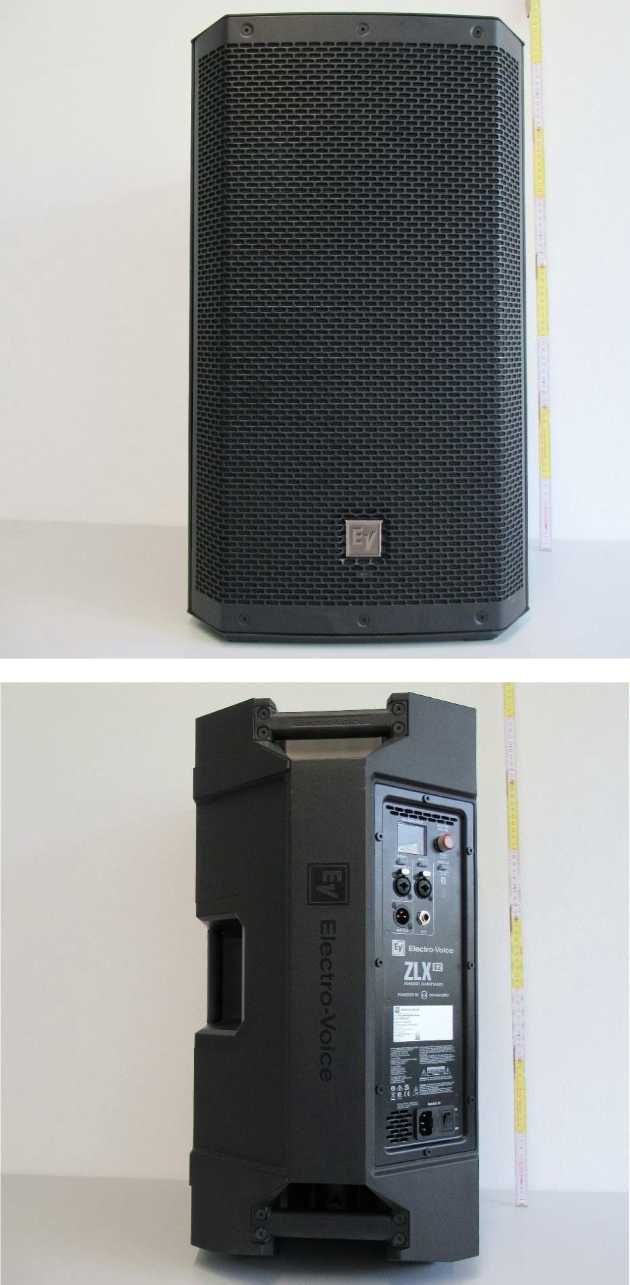
ESV-ZLXG2
Dec 21, 20232-way Powered Speaker
Equipment Class
DTS - Digital Transmission SystemESVD1
May 31, 2005Tritech Detector
Equipment Class
FDS - Part 15 Field Disturbance Sensor
ESV-RF3402
Dec 14, 2004Recessed Wireless Window or Door Magnetic Contact
Equipment Class
DSC - Part 15 Security/Remote Control Transmitter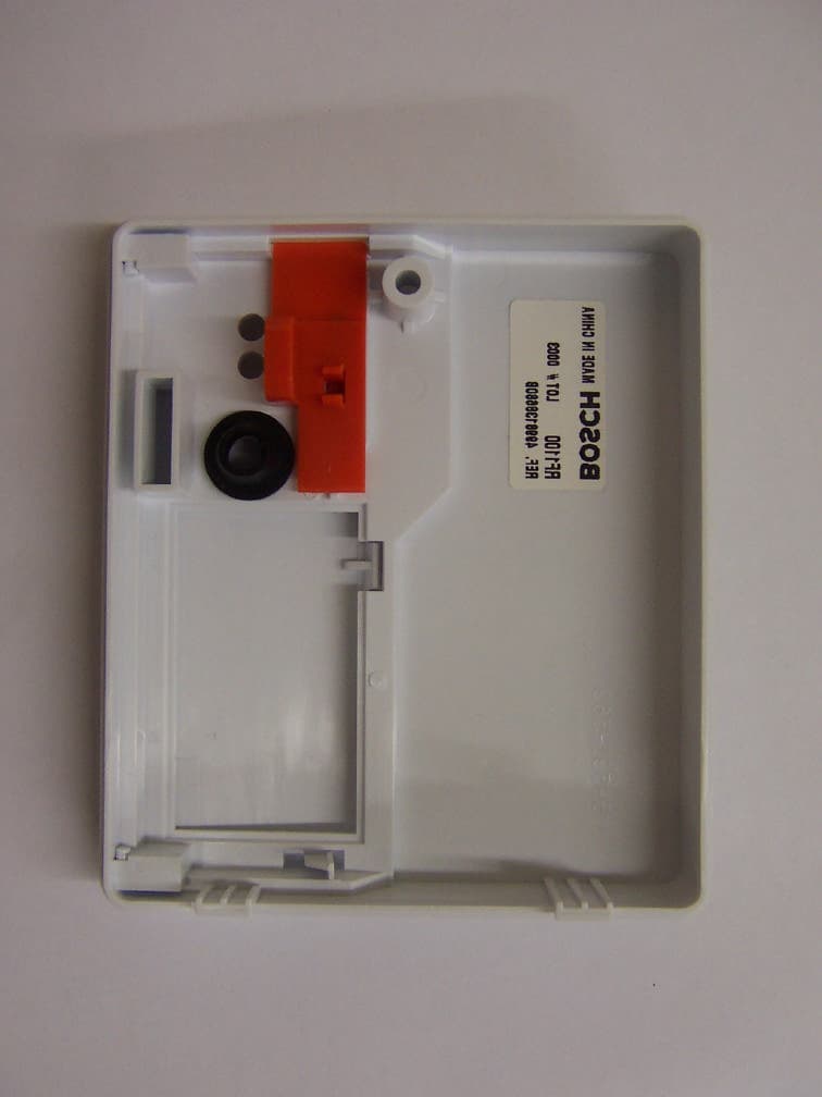
ESV-RF1100
Aug 04, 2004Wireless Glass Break Transmitter
Equipment Class
DSC - Part 15 Security/Remote Control Transmitter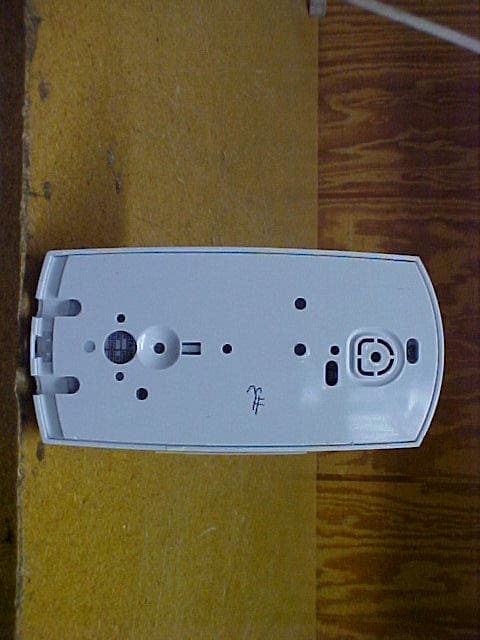
ESV850
Oct 26, 2003PIR/Microwave Intrusion Detector
Equipment Class
FDS - Part 15 Field Disturbance Sensor