ESV9370Tri Tech Ceiling Mount PIR/Microwave Intrusion Det
Bosch Security Systems LLC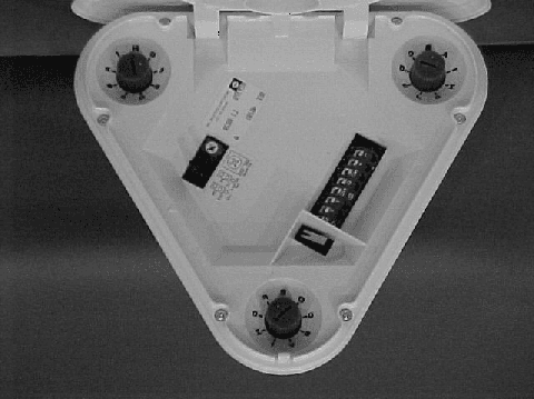
Click to zoom
Application Details
- Equipment Class
- FDS - Part 15 Field Disturbance Sensor
- Date of Grant
- Jan 15, 2002
- Application Purpose
- Original Equipment
- Date of Application
- Jan 15, 2002
- Equipment Note
- Tri Tech Ceiling Mount PIR/Microwave Intrusion Det
- Frequency Range
- 10525.00000000 - 10525.00000000
- Company
- Bosch Security Systems LLC
- Country
- United States
Documents & Files
Document Text
Text extracted from the exhibit documents filed with the FCC. Open a document above to read the original.
Users Manual
DS9370 TriTech Ceiling Mount PIR/ Microwave Intrusion Detector 1.0Specifications •Dimensions (HxDia):3.5 in. x 7 in. (8.9 cm x 17.8 cm) •Coverage:360° by 70 ft. (21.3 m) diameter coverage when mounted on 12 to 25 ft. (3.7 to 7.6 m) high ceilings. A coverage area of 40 ft. (12.2 m) is available when mounted at 8 ft. (2.4 m) and a coverage of 50 ft. (15.2 m) is available when mounted at 10 ft. (3 m). The pattern consists of 69 zones grouped into 21 barriers. Each barrier is 35 ft. (10.7 m) long and 5 ft. (1.5 m) wide at 35 ft. (10.7 m). The barriers are divided into 3 groups of 7 barriers, each of which has a vertical adjustment for custom coverage. •Input Power:9.0 to 15.0 VDC; 29 mA standby, 39 mA in alarm with LEDs enabled. Use only an Approved Limited Power Source. •Standby Power:There is no internal standby battery. 29 mAh is required for each hour of standby time needed. For UL Listed Requirements, four hours of standby current (116 mAh) is required. Standby power must be provided by an Approved Limited Power Source. •Sensitivity:Low/High settings. •Alarm Relay:Silent-operating Form “C” relay. Contacts rated 125 mA, 28 VDC, 3 watts maximum for DCresistive loads. The contacts transfer on alarm for a period of 4 seconds. Some countries require the relay to be connected to a SELV (Safety Extra-Low Voltage) circuit only. Do not use with capacitive or inductive loads. •Tamper:Normally Closed (with cover in place) tamper switch. A wall (base) tamper is included. Contacts rated at 28 VDC, 125 mA, 3 watts maximum. Some countries require the switch to be connected to a SELV (Safety Extra-Low Voltage) circuit only. Connect tamper circuit to a 24-hour protection circuit. •Temperature Range:The storage and operating range is -40° to +120°F (-40° to +49°C). For UL Listed Requirements, the range is +32° to +120°F (0° to +49°C). •Microwave Frequencies: DS9370:10.525 GHz DS9370-C: 10.588 GHz (Export only. Not UL Listed) •Countries of Intended Use: These products are intended for use in the following countries within the European Union and in other countries outside of the European Union: • DS9370:Austria, Belgium, Denmark, Finland, Greece, Luxembourg, Netherlands, Norway, Spain, Sweden. • DS9370-C: United Kingdom, Ireland, France. •US Patent Numbers:This detector is protected by one or more of the following: #4,660,024; 4,764,755; 5,077,548; 5,208,567; 5,262,783; and 5,450,062. Other patents pending. •Compliance: This device complies with Part 15 of the FCC Rules and with RSS-210 of Industry and Science Canada. Operation is subject to the following two conditions: (1)this device may not cause harmful interference, and (2)this device must accept any interference received, including interference that may cause undesirable operation. Changes or modifications not expressly approved by Detection Systems, Inc. can void the user’s authority to operate the equipment. 2.0Installation Considerations •Never install the detector in an environment that causes an alarm condition in one technology. Good installations start with the LED OFF when there is no target motion. It should never be left to operate with the tri-color LED in a constant or intermittent green, yellow, or red condition. NOTE:Microwave energy will pass through glass and most common non-metallic construction walls. •Avoid installations where rotating machines (e.g. ceiling fans) are normally in operation within the coverage pattern. Point the unit away from glass exposed to the outdoors and objects that may change temperature rapidly. Avoid mounting the unit within 1 ft. (0.3 m) of any fluorescent light fixture. Note:The PIR detector will react to objects rapidly changing temperature within its field-of-view. •Eliminate interference from nearby outside sources. 3.0Mounting •Select a location likely to intercept an intruder moving across the coverage pattern. Recommended mounting height range is 12 to 25 feet (3.7 to 7.6 m). A coverage area of 40-70 ft. (12.2- 21.3 m) is available when mounted between 8-12 ft. (2.4-3.7 m). •The surface should be solid and vibration-free. (i.e. drop tiles should be secured if the area above the tiles is used as an air return for HVAC systems). •To open the detector, locate the arrow on the cover of the detector . Turn a screwdriver in the recess between the cover and the base . One side of the cover will remain attached to the base of the detector. DS9370 Installation Instructions© 2001 Detection Systems, Inc. All rights reserved.Page 2 P/N 48781B •If necessary, you may remove the base from the cover by pressing the two cover release tabs inward while lifting the base away from the cover. •Route wiring as necessary to the rear of the base and through the center hole. Note:Be sure all wiring is de-energized before routing. •Firmly mount the base. Depending on local regulations, the base may be directly surface mounted using anchors, mollies, or wing-nuts. It may also be mounted to standard 3.5 in. octagonal electrical box. The detector may also be connected directly to short lengths (short enough to avoid movement of the detector) of ½ in. (1.27 cm) EMT. Hint:Mounting to removable ceiling tiles is not recommended unless a sandwich is made of the base, ceiling tile, and a back plate behind the tile. Mounting Base Wire entrance and/or EMT Mounting. Mounting holes. Tamper Post. Wire entrance for surface mounting. •If ceiling tamper is desired, loosen the tamper post by cutting the 3 tabs and mount the post to the ceiling using a #8 screw . 5.0Wiring CAUTION Only apply power after all connections have been made and inspected. Do not coil excess wiring inside detector. Note:Input power must use only an Approved Limited Power Source. Some countries require that the Alarm and Tamper Contacts be connected to a SELV (Safety Extra-Low Voltage) circuit only. - + NO C NCTTM ALARMTAMPERPOWER + - •Terminals 1 (-) & 2 (+): Power limits are 9 to 15 VDC. Use no smaller than #22 AWG (0.8 mm) wire pair between the unit and the power s…
Text truncated - open the document above for the full version.
Block Diagram
PROPRIETARY DATA DATA CONTAINED HEREIN SHALL NOT BE USED, DUPLICATED OR DISCLOSED IN WHOLE OR PART OUTSIDE OF DETECTION SYSTEMS, INC., WITHOUT EXPRESSED WRITTEN PERMISSION OF SAME. SANBD ECR# DR AUTHDATESYMREVISION RECORD ACCEPTED DRAWINGB06/22/01 PIR SENSITIVITY ADJ. P2 ALARM LEDS LED 1, LED 2 ALARM RELAY K1 MW OSC. Q99 MW DRIVER Q2 MW XMITTER uP U5 PIR PIR PIR DS3 DS2 DS1 MW Receiver Sample & Hold Q1,C33 U4 U1 U4 U2 DATE DRAWN DRAWING TITLE SCALE 1:1 DETECTION SYSTEMS, INC., 130 PERINTON PARKWAY FAIRPORT, NEW YORK, 14450, USA (716) 223 4060, FAX (716) 223 9180 PART NO. 46477B 06/22/01 BLOCK DIAGRAM - DS9370 SHEET 1 OF 1 DRAWING NUMBER DRAWN BY: SAN APPR BY: A46477 Rev. B
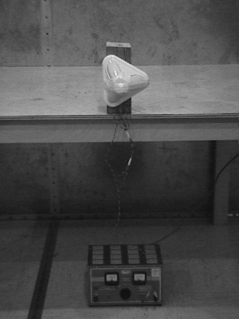
External Photos
Retlif Testing Laboratories R Test Report Number R-9299-3
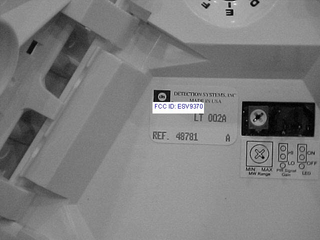
Internal Photos
Retlif Testing Laboratories R Test Report Number R-9299-3 Retlif Testing Laboratories R Test Report Number R-9299-3 Retlif Testing Laboratories R Test Report Number R-9299-3
Operational Description
DS9370 Technical Description Bill DiPoala 6-12-01 The DS9370 is a ceiling Mt. Dual motion detector with 360deg, 70ft diameter coverage. The PIR subsystem incorporates three pyro sensors and lenses. The additional sensors provide improved signal to noise ratios over single pyro designs. The MW subsystem is similar to previous designs but we have added a low noise amplifier to the MW front end to again improve the signal to noise ratio. The DS9370 schematic, product specification and software specification should be used in addition to this document to fully understand its operation. Power supply: The supply input voltage is regulated down to +5VDC via U3. D3 provides reverse power protection and RV3 provides over-voltage protection. Microwave Subsystem: The MW subsection consists of an X band transceiver. Its output produces a Doppler signal that is amplified and then processed to determine human motion. The MW oscillator is FET based and is DRO stabilized. The antennas are a monopole configuration a with a separate transmit and receive element. The receiver incorporates a low noise amp that feeds the mixer diode. The low noise amp requires a negative 2.76V supply. The uP clock output pin with D5, D4, C46 and C47 from a switching supply. The Up provides the required MW drive pulses. Q2 is used drive the MW FET. The receiver is connected to an amplifier U4-4 via a samples and hold circuit formed by Q1 and C33. A second stage of gain is provided by U4-2. The user may adjust the range of the MW detection by adjusting R37. The amplified MW Doppler signal is then fed to the A/D input of the uP. Further signal processing is performed within the uP (see uP software specification). PIR Sub System: The PIR sub system incorporates 3 pyro sensors and three separate PIR amplifier channels formed by U1, U2 and part of U4. The analog signals are fed directly to the A/D pins on the uP where all of the signal processing is performed (see software spec.). The PIR subsystem has a temperature compensation circuit to provide consistent catch performance at elevated temperatures. The 3 PIR channels are processed independently for an alarm condition. The Alarm relay will activate when a MW alarm coincides with a PIR alarm from any or all PIR channels. Microprocessor: The DS9370 uses the PIC 16C715. Refer to the DS9370 Software Specification for further details.
Test Report
Retlif Testing Laboratories R Test Report Number R-9299-3 REPORT OF MEASUREMENTS GENERAL Applicant:Detection Systems, Inc. Device:10.525 GHz Field Disturbance Sensor Model:DS9370 Serial Number:N/A FCC ID:ESV9370 Input Power Requirements:9 to 15 VDC, 29 mA (12 VDC Nominal) Rule Section:Part 15, Subpart C, Section 15.245 TEST METHODS PERFORMED 15.245 (b)Radiated Emissions, Fundamental 15.245 (b)(1)Radiated Emissions, Harmonics 15.245 (b)(3)Radiated Emissions, Band Edges 15.245 (b)(3)Radiated Emissions, Spurious Emissions, 30 MHz to 52.625 GHz Retlif Testing Laboratories R Test Report Number R-9299-3 TEST RESULTS 15.245 (a)The device is an intentional radiator used as a field disturbance sensor. 15.245 (b)The device operates within the 10.500 to 10.550 GHz frequency band. The field strength of the fundamental emission did not exceed 2500 millivolts per meter, average. 15.245 (b)(1)The device does not produce harmonic emissions below 17.7 GHz. 15.245 (b)(1)(i)The device is intended to be used only within buildings and the field strength of harmonic emissions did not exceed 25.0 millivolts per meter. 15.245 (b)(2)All radiated emissions measurements were extrapolated to the specified 3 meter test distance. 15.245 (b)(3)The emissions radiated outside of the specified frequency band of 10.500 to 10.550 GHz did not exceed the general radiated emission limits of 15.209. 15.245 (b)(4)The requirements of 15.35 for averaging pulsed emissions and limiting peak emissions were met. Retlif Testing Laboratories R Test Report Number R-9299-3 NOTES 15.31 (a)(b)All measurements were made in accordance with ANSI C63.4:1992. 15.31 (c)The device does not use swept frequency techniques. 15.31 (d)All testing was performed on Retlif Testing Laboratories Ronkonkoma, NY test site which has been listed with the FCC. 15.31 (e) Variation of the radiated signal level of the fundamental frequency component was performed with the supply voltage varied between 85 and 115% of nominal (12 VDC). This was also performed at 85% of the minimum and 115% of the maximum rated input voltage range. 15.31 (f)(1)Where testing was performed at distances other than the specified test distance, the obtained readings were extrapolated to the specified test distance using an inverse linear-distance extrapolation factor (20dB / decade) for measurements between 30 MHz and 40 GHz. 15.31 (f)(5)The device was rotated 360° in order to maximize the radiated emissions. The maximum field strength observed has been reported. 15.31 (g)All consumer accessible controls were adjusted in order to maximize emissions (MW Range Control). A one meter length of unshielded twisted pair wire was connected to each of the relay and tamper outputs. 15.31 (m)The device operates at a single frequency of 10.525 GHz. 15.31 (o)All emissions within 20 dB of the specified limits have been reported unless otherwise stated. 15.33 (a)(2)The device operates above 10 and below 30 GHz at a frequency of 10.525 GHz. Therefore radiated emissions measurements were made from 30 MHZ to 52.625 GHz, the fifth harmonic. Retlif Testing Laboratories R Test Report Number R-9299-3 DUTY CYCLE Four microsecond (7 :Sec) pulses are applied to the gunn diode at a repetition rate of 7.75kHz (off time 125 :Sec). This yields a duty cycle of 5.6%, 7 :Sec divided by 125 :Sec. This duty cycle was applied to the obtained peak readings in order to determine the average value of the emissions. TEST DISTANCES In order to obtain adequate system sensitivity at the harmonic frequencies of interest, it was necessary to perform certain measurements at a distance less than 3 meters. Care was taken to ensure that all measurements were taken in the far field region. The antenna was determined to be in the far field IFF: d $ 2 D 2 ' 8 Where: d = Test Distance D = Largest Antenna Length 8 = Wavelength at the Frequency of Interest Solving for d yields the minimum test distances shown in the table below. Also shown is the actual test distance utilized. Frequency GHz Minimum Test Distance Meters Actual Test Distance Meters 10.5252.73 21.0501.52 31.5751.01 42.1000.51 52.6250.71 Retlif Testing Laboratories R Test Report Number R-9299-3 SPECTRUM ANALYZER DESENSITIZATION CONSIDERATIONS Due to the nature of the emissions being measured, care was taken to ensure that the resolution bandwidth of the spectrum analyzer was adequate to provide accurate peak field strength measurements. The following formula was utilized: Pulse Desensitization (*) = 20 log (Pulsewidth * bandwidth * 1.5) Setting the above equal to zero and utilizing the 7.0 microsecond pulsewidth yields a minimum required bandwidth of 95.2 kHz. The 1 MHz bandwidth specified in ANSI C63.4 was utilized for all fundamental and harmonic measurements. Retlif Testing Laboratories R Test Report Number R-9299-3 TEST DATA RADIATED EMISSIONS, FUNDAMENTAL 15.245 (b) Retlif Testing Laboratories R Test Report Number R-9299-3 TEST SAMPLE: 10.525 GHz Field Disturbance Sensor FCC ID: ESV9370 APPLICANT: Detection Systems, Inc. TEST METHOD: Radiated Emissions, Fundamental SPECIFICATION: FCC Part 15, Section 15.245 (b) PERFORMED BY: P. Lananna DATE: December 27, 2001 Field Strength of Fundamental Frequency GHz Antenna Position H / V EUT Orientatio n X / Y/ Z Meter Reading dBuV Antenna Factor +dB Corrected Reading dBuV/m Converted Reading mV/m Limit at 3 Meters mV/m 10.525H-1.1X75.030.0105.0177.82,500 V-1.1X71.930.0101.9124.42,500 H-1.2Y71.230.0101.2114.82,500 V-1.0Y77.030.0107.0223.92,500 H-1.0Z82.130.0112.1402.72,500 V-1.2Z70.330.0100.3103.52,500 Detector Function: Peak Test Distance: 3 Meters Resolution Bandwidth: 1 MHz Video Bandwidth: 3 MHz Retlif Testing Laboratories R Test Report Number R-9299-3 TEST SAMPLE: 10.525 GHz Field Disturbance Sensor FCC ID: ESV9370 APPLICANT: Detection Systems, Inc. TEST METHOD: Radiated Emissions, Fundamental, Input Voltage Variation SPECIFICATION: FCC Part 15, Section 15.245 (b), 15.31(e) PERFORMED BY: P. LANANNA DATE: DECEMBER 27, 2001 Input Vol…
Text truncated - open the document above for the full version.
Contact Information
Applicant
Peter Namisnak(Sr. Regulatory Compliance Coordinator)
Technical Contact
Retlif Testing LaboratoriesThomas Schnieder
[email protected]1 631 737 1500
795 Marconi Avenue · Ronkonkoma, New York · United States
Non-Technical Contact
Retlif Testing LaboratoriesMichelle White
[email protected]1 631 737 1500
Test Firm
Retlif Testing LaboratoriesMichael Bozza
Technical Specifications
| # | Rule Parts | Frequency Range | Power Output |
|---|---|---|---|
| 1 | 15.245 | 10.53 GHz - 10.53 GHz | - |
Other Applications from Bosch Security Systems LLC
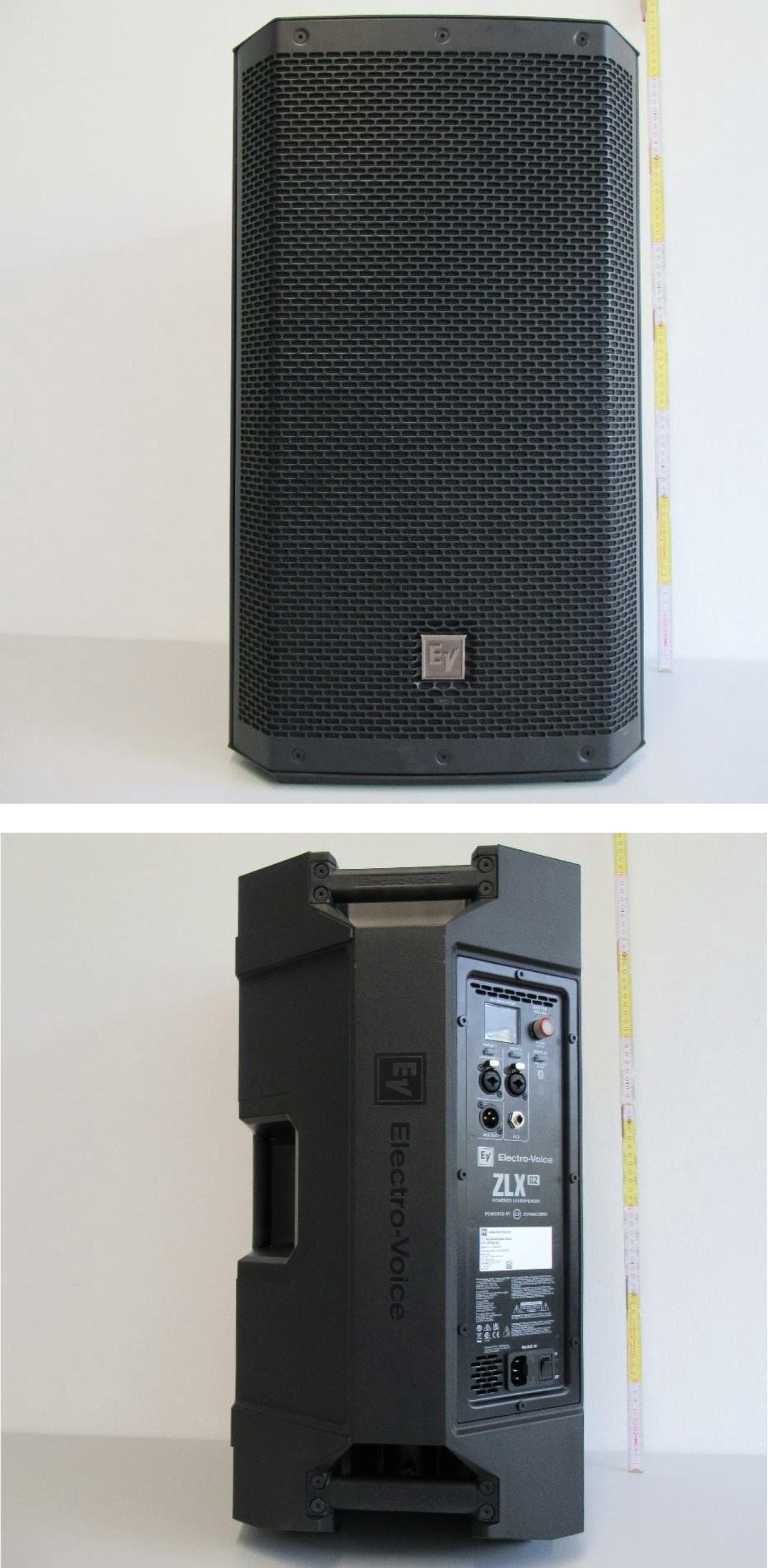
ESV-ZLXG2
Dec 21, 20232-way Powered Speaker
Equipment Class
DTS - Digital Transmission SystemESVD1
May 31, 2005Tritech Detector
Equipment Class
FDS - Part 15 Field Disturbance Sensor
ESV-RF3402
Dec 14, 2004Recessed Wireless Window or Door Magnetic Contact
Equipment Class
DSC - Part 15 Security/Remote Control Transmitter
ESV-RF1100
Aug 04, 2004Wireless Glass Break Transmitter
Equipment Class
DSC - Part 15 Security/Remote Control Transmitter
ESV850
Oct 26, 2003PIR/Microwave Intrusion Detector
Equipment Class
FDS - Part 15 Field Disturbance Sensor