ESVDS720ILong Range Dual PIR/Microwave Intrusion Detector
Bosch Security Systems LLC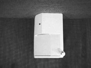
Click to zoom
Application Details
- Equipment Class
- FDS - Part 15 Field Disturbance Sensor
- Date of Grant
- Feb 04, 2001
- Application Purpose
- Original Equipment
- Date of Application
- Feb 04, 2001
- Equipment Note
- Long Range Dual PIR/Microwave Intrusion Detector
- Frequency Range
- 10525.00000000 - 10525.00000000
- Company
- Bosch Security Systems LLC
- Country
- United States
Documents & Files
Document Text
Text extracted from the exhibit documents filed with the FCC. Open a document above to read the original.
Users Manual
Installation Instructions DS720i Long Range Dual PIR/Microwave Intrusion Detector 1.0Description The DS720i is a long range dual passive infrared (PIR)/microwave (mW) intrusion detector that utilizes state-of-the-art signal processing to maximize catch performance and reduce false alarms. 2.0Specifications •Description: DS720i Long Range Dual PIR/Microwave Intrusion Detector. •Input Power: 9 to 15 VDC, 32 mA DC nominal @ 12.0 VDC (up to 60 mA DC during walk testing, stored alarms, or trouble conditions). •Standby Power: There is no internal standby battery. Connect to DC power sources capable of supplying standby power if primary power fails. 32 mA-H required for each hour of standby time needed. Four hours (128 mA-H) minimum are required for Underwriters Laboratories' Certificated installations. •Alarm Relay: Silent operating Form "C" reed relay. Contacts rated 3 watts, 125 mA, 28 VDC maximum for DC resistive loads; and protected by a 4.7 ohm, 1/2 Watt resistor in the common "C" leg of the relay. Do not use with capacitive or inductive loads. Alarm relay contacts on terminals 3,4 and 5. •Tamper: Normally Closed (with cover in place) tamper switch. Contacts rated at 28 VDC, 125 mA maximum. Tamper contacts on terminals 6 and 7. •Trouble: Normally Closed dry contact output on terminals 8 and 9. The contacts are rated at 28 VDC, 125 mA maximum. Open during trouble condition. •Operating Temperature: -20° to +120°F (-29° to +49°C). For U.L. Listed Requirements, the temperature range is +32° to +120°F (0° to +49°C). •Microwave Frequencies: •DS720i: 10.525 GHz •DS720i-A: 9.9 GHz •DS720i-B: 10.687 GHz •Coverage: Standard Broad:90 ft. by 70 ft. (27 m by 21 m) (OA90) Optional Long Range:120 ft. by 25 ft. (37 m by 8 m) (OA120) Standard Long Range:300 ft. by 15 ft. (91 m by 4.6 m) (OA300) •Options: TC6000 Test Cord and OA120 Optical Module. •U.S. Patent Numbers: # 4,660,024, # 4,764,755, #5,077,548, #5,083,106, # 5,208,567, # 5,262,783, and # 5,450,062. Other patents pending. •Dimensions: 8.25 in. L x 5 in. W x 5.19 in. H (21 cm L x 13 cm W x 13.2 cm H) 3.0Installation Hints Never install the detector in an environment that causes a constant alarm in one technology; it should never be left to operate with the green, yellow or red LED ON. Point the unit AWAY from outside traffic (e.g. roads, alleys, and parking lots). Remember: Microwave energy will pass through glass and most common nonmetallic construction walls. Point the unit AWAY from glass exposed to the outdoors and objects that may change temperature rapidly. Remember: The PIR detector will react to objects rapidly changing temperature within its field-of-view. Avoid installations where rotating machines (e.g. ceiling fans) are normally in operation within the coverage pattern. If using the anti-mask feature, avoid locations where people or objects may be moving within 3 ft. (1 m) of the detector. 4.0Mounting Select a location that is most likely to intercept an intruder moving across the coverage pattern (review coverage patterns on page 6). The recommended mounting height for the 300 ft. x 15 ft. (91 m x 4.6 m) coverage is 10 ft. (3 m). The recommended mounting height for the 90 ft. x 70 ft. (27 m x 21 m) and 120 ft. x 25 ft. (36.6 m x 8 m) coverages is 7.5 ft. (2.3 m). The surface should be solid and vibration-free. Remove the cover by inserting a flathead screwdriver or other flat object into the slot at the bottom of the cover, and twist until the cover snaps free of the front tabs on the base. Lift the cover up and away to clear the rear base tabs. Do not bend or remove the microwave antenna located on the front of the permanent reflecting mirror. Remove the circuit board from the base by pressing the two circuit board retainer tabs outward while lifting the circuit board away from the base. Select and break away the appropriate thin wall wire entrance and mounting hole coverings in the base. Using the base as a template, mark the location of the mounting holes on the mounting surface, and pre-start the mounting screws. Route wiring as necessary to the rear of the base and through the wire entrance, then firmly mount the base to the mounting surface. MIN MAX PIR NV MW NV AM MW Terminal Strip Set-up Switch Bank Microwave Range Adjustment Tamper Switch PIR Noise Voltage Pins Microwave Noise Voltage Pins Microwave Antenna DO NOT TOUCH! Extra Terminals Anti-Mask Transmitter Light Pipe 12345678 Figure 1: Inside View of DS720i Detection Systems, Inc., 130 Perinton Parkway, Fairport, New York, USA 14450-9199 (716) 223-4060 • (888) 289-0096 • Fax: (716) 223-9180 Copyright © 2000 Detection Systems, Inc. DS720i Installation Guide P/N: 43744B 09/00 DS720i Installation Guide © 2000 Detection Systems, Inc. All rights reserved. Page 2 Bracket Wire Entrance Corner Mount Holes (4) Surface Mount Holes (4) Surface Wire Entrance Base Cover Tabs Rear Wire Entrance Retainer Tabs Figure 2: DS720i Base Be sure all wiring is unpowered before routing. Return the circuit board to the base by first inserting the bottom of the circuit board into the cutouts at the bottom of the base, then snapping the top into place. 3.1Tamper Switch Installation The tamper switch is designed to prevent any unauthorized opening or manipulating of the B334 Mounting Bracket once it has been mounted. The tamper switch mounts to the inside of the bracket using the supplied circuit board mount. Jumper Pins for Wall Tamper Jumper Pins for Bracket Tamper Tamper Terminal Block Wall Tamper Bracket Tamper Figure 3: Optional Tamper Switch Refer to Figure 4 when installing the tamper switch into the B334 Mounting Bracket. Top View of B334 Mounting Bracket Install Tamper Switch Here Fit spring through hole in back of mounting bracket Peel double-sided tape Figure 4: Installing the Tamper Switch The tamper switch's jumper pins determine whether the wall tamper and bracket tamper features are enabled or disabled. See Figure 5 to set the jumper pins. Jumper Pins for Wall Tamper Jumper Pins for Br…
Text truncated - open the document above for the full version.
Block Diagram
DATE DRAWN DRAWING NUMBER DRAWING TITLE DRAWN BY: SAN APPR BY: SCALE A41387REV-D ds ® SHEET 1 OF 1 DETECTION SYSTEMS, INC. BLOCK DIAGRAM (DS720i) 130 PERINTON PARKWAY FAIRPORT, NEW YORK, 14450-9099, USA (716) 223 4060, FAX (716) 223 9180 SAN SAN SAN 10596 11076 ECR# DR AUTHDATESYMREVISION RECORD ACCEPTED DRAWING ADDED MISSING MICROWAVE ANITMASK ANTIMASK WAS INCORRECTLY SPELLED 4/29/99 B C D 4/29/99 3/10/00 5/11/00 PART NO. 41387B EMH EMH EMH PROPRIETARY DATA DATA CONTAINED HEREIN SHALL NOT BE USED, DUPLICATED OR DISCLOSED IN WHOLE OR PART OUTSIDE DETECTIONS SYSTEMS INC. WITHOUT EXPRESSED WRITTEN PERMISSION OF SAME. PROCESSOR ALARM OUTPUT LED OUTPUT TROUBLE OUTPUT MEMORY OUTPUT MICROWAVE ANTIMASK PIR ANTIMASK PIR MICROWAVE USER INPUT SWITCHES
Cover Letter(s)
To:Commission Reviewer From:Richard King Certification Department Coordinator Elite Electronic Engineering RE:FCC ID ESVDS720I Applicant:Detection Systems, Inc. Corr. Ref. #: 731 Confirm. #: Date: In reference to a request for certification from Detection Systems, Inc Elite performed a certification of the above referenced product manufactured by Detection Systems, Inc. Deficiencies were discovered during the certification process. The noted deficiencies were addressed in correspondence between the appropriate test facilities and Elite Electronic Engineering. The correspondence is indicated below. Questions from Elite dated January 23, 2001. Upon review of the Model DS 720I Microwave/PIR Intrusion Detector, it was determined that additional information is required before the certification can continue. Please address the following issues: 1. The input voltage is indicated as 9-15VDC in Exhibit D User’s Manual and 6-15VDC in Exhibit B the technical description. Please indicate the proper input voltage to the device. 2. Please justify the exclusion of the conducted emissions test required pursuant to 15.207. 3. Please include the test setup photographs or drawings for the radiated emissions test and conducted emissions test. Response to Elite’s questions dated January 30, 2001. 1. The input voltage is indicated as 9-15VDC in Exhibit D User's Manual and 6-15VDC in Exhibit B the technical description. Please indicate the proper input voltage to the device. Response: 9-15 VDC as stated in User's Manual and Test Report. 2. Please justify the exclusion of the conducted emissions test required pursuant to 15.207. Response: Please see attached data named: CE data.pdf 3. Please include the test setup photographs or drawings for the radiated emissions test and conducted emissions test. Response: Please see attached photographs name:CE photo.jpg & RE photo.jpg Comments: Responses to questions were proper and satisfactory certification was granted. Richard King
ID Label/Location Info
1.4 (35.56) 1 (25.40) FCC ID: ESVDS72ØI DETECTION SYSTEMS, INC. NOTES: 1. Dimensions are in inches (millimeters). 2. Printing to be black on white background. 3. Borders not to show. 4. Paper to be white 60# litho stock with pressure sensitive adhesive backing compatible with ABS plastic. 5. To be supplied on rolls. P/N 22708C A B C ACCEPTED DRAWING Delete "GLOSS" from note 4 Added (I) to FCC ID# GJR PRJ EEV 2/21/90 11/8/91 12/20/00 ECR# DR AUTHDATESYMREVISION RECORD BD 1396 12316 DRAWN BY: GJR APPR BY: A22708REV-C DS720 FCC LABEL 2/8/90 3:1 DATE DRAWN DRAWING NUMBER DRAWING TITLE SCALE SHEET 1 OF 1 DETECTION SYSTEMS, INC. 130 PERINTON PARKWAY FAIRPORT, NEW YORK, 14450-9199, USA (716) 223 4060, FAX (716) 223 9180 PART NO. 22708C THIS DEVICE COMPLIES WITH PART 15 OF THE FCC RULES. OPERATION IS SUBJECT TO THE FOLLOWING TWO CONDITIONS: (1) THIS DEVICE MAY NOT CAUSE HARMFUL INTERFERENCE, AND (2) THIS DEVICE MUST ACCEPT ANY INTERFERENCE RECEIVED, INCLUDING INTERFERENCE THAT MAY CAUSE UNDESIRED OPERATION.
Operational Description
DS720i TECHNICAL DESCRIPTION Eric Hinkston 10-12-98 The DS720i is a long range dual PIR/Microwave motion detector. The detection coverage consists of a standard 300’ x 10.5’ pattern or an optional 90’ x 70’ pattern. The enclosure design is similar to the DS794z and uses the existing DS794z optics. Feature set will include the following: MW and PIR Noise Voltage Output Form C Relay Input power from 6-15 VDC Cover Tamper PIR and MW Self Test Trouble Output Relay MW Range Adjust Antimask Delay Processing Optional Active IR Antimask MW Frequencies 9.900GHz (DS720i-A and DS720ia-A only for United Kingdom) 10.525 GHz (DS720I and DS720IA) 10.687GHz (DS720i-B and DS720ia-B only for France) Unit Sensitivity High/Int Antimask On/Off Antimask Sensitivity High/Low Motion Monitor Off/1 Day/4 Day/30 Day Memory On/Off +5V Regulator The 5V regulator (U1) consists of an LM2931 voltage regulator. RV3 protects the voltage regulator from harmful voltage spikes. The UNREG line is used to drive all high current loads through emitter followers to prevent noise spikes from entering the amplifiers. PIR Amplifier The PIR amplifier utilizes a LM358 (U3). The DET is AC coupled to the first amp stage via a non-polar capacitor (C31). The gain of the first amp is determined by the ratio of R24 to R36. The bandwidth of the first stage is limited by the values of C21 and C22. The gain of the second stage is determined by the ratio of R26 to R37. The bandwidth is limited by C24 and C30. The amplified signal is coupled to one of the analog inputs of the microprocessor (U4) where signal processing is performed. Microwave Subsystem The MW subsystem utilizes a micro-strip Microwave Transceiver. The transmitter consists of a FET oscillator (Q99) biased through R99. The frequency of oscillation is determined by the electrical/physical properties of the ceramic resonator Y99. Fine tuning of the transmitter is accomplished by adjusting the position of the tuning screw located in the back of the plastic back shield. The transmit and receive antenna consist of patch antenna design. The antenna is located on top of the PIR focusing mirror. The transmitter drive pulse is generated by microprocessor U4. The drive pulses are applied to Q99 by Q10through P3, and are 20 microseconds on-time, and 1 millisecond off-time. The receiver incorporates a balanced mixer design consisting of two diodes present in D99. Equal amounts of RF energy are applied to each diode, one from the transmitter and one from the receiver section. This balancing of the RF energy should produce a nominal pulse voltage on the IF output (MW2) of 0Vp, and should always be less than +/- 0.2Vp. The IF output is fed to a sample-and-hold circuit Q1 via AC coupling cap C20. The sample pulse is generated by the microprocessor and should be 10 microseconds long and centered in the middle of the drive pulse. The signal is fed to two stages of amplification U2-1 and U2-4. The MW range is adjusted by potentiometer R31. This amplified signal is fed into one of the analog inputs of the microprocessor where the rest of the signal processing is done (see software spec.). Microprocessor Functions See DS720i Software Specification.
Schematics
+ + TOOLING HOLE TOOLING HOLETOOLING HOLETOOLING HOLETOOLING HOLETOOLING HOLE TOOLING HOLETOOLING HOLETOOLING HOLETOOLING HOLETOOLING HOLE TOOLING HOLETOOLING HOLETOOLING HOLETOOLING HOLETOOLING HOLE TOOLING HOLETOOLING HOLETOOLING HOLETOOLING HOLETOOLING HOLETOOLING HOLETOOLING HOLETOOLING HOLE TOOLING HOLETOOLING HOLE Rev Part Number Manuf. ReviewedTest ReviewedRelease ApprovalRelease Date Schematic Initial/Date Design Approval or in part outside Detection Systems Inc., Design Review Date Title without expressed written permission of same used, duplicated or disclosed in whole **** PROPRIETARY DATA **** Data contained herein shall not be Drawn By: 1 23 C B A 4321 ABCD D 4 REV DRAWN BY DATE DESCRIPTION Created:Sheet: PC Board Number/Revision TOOLING HOLETOOLING HOLE + TOOLING HOLE TOOLING HOLE +--+ C NCNO + + + + + Green Red + + + + TOOLING HOLE TOOLING HOLE SMOBC SMOBC NC C NO + + IN GND OUT TOOLING HOLE TOOLING HOLE OSC2 C NC H RWJ * * * * * * 1 OF 1 10/9/97 MWNV B 2/13/98 RELEASED FOR PRODUCTION BM Trouble Relay Output Alarm Relay Output * VALUES MAY CHANGE FORTHESE LOCATIONS, CHECK THE BILLOF MATERIALS FOR PROPER VALUES * ERIC HINKSTON E. HINKSTON LONG RANGE DUAL INTRUSION DETECTOR ECR 7961 6/02/98 C EMH TO ANTIMASK LED SW-2SW-3SW-4SW-5SW-6SW-1 LED OPERATION (ON/OFF)MOTION MONITOR (SEE TABLE BELOW) SW-7SW-8 PASSIVE INFRARED ANTIMASK (ON/OFF)MICROWAVE ANTIMASK (ON/OFF)PIR SENSITIVITY (ON = INTERMEDIATE / OFF = HIGH) MOTION MONITOR TABLE SPRAY DETECT PASSIVE INFRARED ANTIMASK (ON/OFF)AND/OR MODE (JUMPERED= OR / NOT JUMPERED = AND) SW-3 SW-4 OFF OFF OFF1 DAY ON OFF4 DAY OFF ON30 Day ON ON TROUBLE RELAY DUAL ALARM/TROUBLE LED ALARM RELAY P1 PIRNOISEVOLTAGE MICROWAVE ANTIMASK ON/OFF LED ON/OFF PIR SENSITIVITY MOTION MONITOR MOTION MONITOR PIR ANTIMASK SPRAY DETECT ON/OFF MOTION MONITOR (SEE TABLE BELOW) D36944 EMH ECR 10321 11/30/99 D DIP SWITCH SELECTION TABLE DS720i Cover Tamper Switch FROM ANTIMASK DETECTION PCB Spare Terminals Not Connected AND/OR MODE SELECT PIR ANTIMASK ON/OFF * * Optional parts seeBOM for correct value DS720i ANTIMASK DELAY TIMER ANTIMASK DELAY TIMER (ON/OFF) A E 02/17/00 ECR 10597 EMH F 07/25/00 EMH ECR 11729 (NO SCHEMATIC CHANGES) HRWJ ECR 11443 08/29/00 G 09/14/00 ECR 11785 N49 N54 N36 N37 N38 N39 N43 N44 N48 N41 N18 N50 N45 N25 100R15 .01UFC40 C17.01UF R39 1M 5%47PFC38 C4847PF5% R52 3.9K .01uF C22 SAMPLE/HOLD_PULSE R21 1.2M R40 1.2M 41 K2 6 10 9 18171615141312 2827262524232221 543 20 7 819 1 2 11 U4 PIC16C72 H46 H40 U1 LM7805 5V STANDUP R73 5K W/ADJUST_HOLE R51270 R31 5K 6.3V100uFC8 C7 100uF 6.3V 7 10 S1 +5V PIR_ANTIMASK_INPUT 123 P1 5.6VMMSZ4690D8 12 TS2 S2 H42 FID1 FID3 FID4 FID2 H38 H39 H6 X3 R204.7K +5V +5V R454.7K R7133 C3547UF6.3VLL 123 P2 123 P3 H43 H1 .001UFC39 R681M +5V R4747K +5V R12470K 9 8 S1 11 6 S1 13 4 S1 3 14 S1 15 2 S1 1 16 S1 N12 N16 MEMORY_INPUT SELF_TEST N9 N96 N8 +5V D94153 5.6K R67 4153D2 C2 27pF N66 +5V R1447K R37100K N27 47KR16 +5V N30 100KR59 +5V R1847K R58100K N32 +5V R1947K 100KR57 N29 47KR72 +5V R35100K N2 N28 R547K 100KR36 C11.001UF 5 12 S1R631K 1KR60 D6MMSZ46905.6V 47KR6 D5MMSZ46905.6V RT110K 5% PIR_ANTIMASK_DRIVE_PULSE N3 R70 1K N13 N4 +5V +5V LED1L934SRC/DRed +5V D1 1N4007 +5V R25150 C6.0047uF63VFilm10% C26 100pF N24 N31 6.3V100uFC21 15KR8 1M R24 N26 N23 6.3V100uFC30 R715K 1M R26 R561K C29.0047uF63VFilm10% C9 100uF 6.3V +5V SAMPLE/HOLD_PULSE MW_DRIVE_PULSE PIR_ANTIMASK_INPUT C28.022uF100VFilm C34.22uF63VFilm 25 K1 4153D4 2 3 K2 LED2L59SRSGC/C3_pinBi_Color R28150 R27150 +5V 100R61 N1N83 PIR_ANTIMASK_DRIVE_PULSE N40 N35 R171K +5V 100KR62 6.3V100uFC13 C3110uF10VNP R10470K 6.3V100uFC12 R46220K +5V 6.3V100uFC32 Q1J176 MW_DRIVE_PULSE 1K R13 6.3V100uFC15 Q10 BCW68 100pFC50 C2047uF6.3VLL 5.6VMMSZ4690D3 R43 100K MEMORY_INPUT 1 34 K1 R4 4.7 1/2W 31VDCRV2 31VDCRV1 18VDCRV4 H36 R22470K R31K +5V .01uFC19 R53 1K +5V DS1 DSI-2 C25.1uF63VFilm H30 12 411 13 14 LM324 U2 X2H31 100pFC47 4 65 8 7 U3 LM358 R3310M .047uF C5 R6418K SELF_TEST .01uF C24 R11270K1MR29 C14100uF6.3V 1%100KR48 47R34 R238.2K 1MR30 Q2MMBT5089 H4H2 1 8 32 4 U3 LM358 5 411 6 7 U2 LM324 +5V +5V 8 9 114 10 LM324 U2 1 2 114 3 LM324 U2 N21 N6 N20 123456789 10 TS1 1%100KR38 C4.0068uF100VFilm 18VDCRV3 R3233K .01uFC23 C3.033uF100VFilm 100KR42 1%100KR44 1%100KR50 +5V +5V +5V H3H5 H10 H8H7H9H29H27H26H28 H20H18H16H17H19 H24H22H21H23H25 H15H13H11H12H14 H32 H33 H34 H35 X4 C10 .0033uF 100VFilm N82 470R1 H37 6.3V100uFC33 BCW68 Q9 5.6VMMSZ4690D7 1K R54 +5V C11000PF50V5% C27.01UF .01UF C36 6.3V100uFC18 N5 N7 N10 N15 +5V 100KR41 N17 N19 N22 N33 1K R65 C37.001UF N34 R66100 N11 N14 47KR49 R5510.0K1% +5V R691M H41 H44H45 J1 0 N42 N51 N52 N53 N46
Test Report
REPORT OF MEASUREMENTS GENERAL Applicant:Detection Systems, Inc. Device:10.525 GHz Field Disturbance Sensor Model:DS 720i Serial Number:N/A FCC ID: ESVDS720I Input Power Requirements: 9 to 15 VDC, 60 mA (12 VDC Nominal) Rule Section:Part 15, Subpart C, Section 15.245 TEST METHODS PERFORMED 15.245 (b)Radiated Emissions, Fundamental 15.245 (b)(1) Radiated Emissions, Harmonics 15.245 (b)(3) Radiated Emissions, Band Edges 15.245 (b)(3) Radiated Emissions, Spurious Emissions, 30 MHz to 52.625 GHz TEST RESULTS 15.245 (a)The device is an intentional radiator used as a field disturbance sensor. 15.245 (b)The device operates within the 10.500 to 10.550 GHz frequency band. The field strength of the fundamental emission did not exceed 2500 millivolts per meter, average. 15.245 (b)(1)The device does not produce harmonic emissions below 17.7 GHz. 15.245 (b)(1)(i)The device is intended to be used only within buildings and the field strength of harmonic emissions did not exceed 25.0 millivolts per meter. 15.245 (b)(2)All radiated emissions measurements were extrapolated to the specified 3 meter test distance. 15.245 (b)(3)The emissions radiated outside of the specified frequency band of 10.500 to 10.550 GHz did not exceed the general radiated emission limits of 15.209. 15.245 (b)(4)The requirements of 15.35 for averaging pulsed emissions and limiting peak emissions were met. NOTES 15.31 (a)(b)All measurements were made in accordance with ANSI C63.4:1992. 15.31 (c)The device does not use swept frequency techniques. 15.31 (d)All testing was performed on Retlif Testing Laboratories Ronkonkoma, NY test site which has been listed with the FCC. 15.31 (e) Variation of the radiated signal level of the fundamental frequency component was performed with the supply voltage varied between 85 and 115% of nominal (12 VDC). This was also performed at 85% of the minimum and 115% of the maximum rated input voltage range. 15.31 (f)(1)Where testing was performed at distances other than the specified test distance, the obtained readings were extrapolated to the specified test distance using an inverse linear-distance extrapolation factor (20dB / decade) for measurements between 30 MHz and 52.625 GHz. 15.31 (f)(5)The device was rotated 360° in order to maximize the radiated emissions. The maximum field strength observed has been reported. 15.31 (g)All consumer accessible controls were adjusted in order to maximize emissions (MW Range Control). A one meter length of unshielded twisted pair wire was connected to each of the relay and tamper outputs. 15.31 (m)The device operates at a single frequency of 10.525 GHz. 15.31 (o)All emissions within 20 dB of the specified limits have been reported unless otherwise stated. 15.33 (a)(2)The device operates above 10 and below 30 GHz at a frequency of 10.525 GHz. Therefore radiated emissions measurements were made from 30 MHZ to 52.625 GHz, the fifth harmonic. DUTY CYCLE Twenty microsecond (20 μSec) pulses are applied to the gunn diode at a repetition rate of 1kHz. This yields a duty cycle of 2%, 20 μSec divided by 1000 μSec. This duty cycle was applied to the obtained peak readings in order to determine the average value of the emissions. TEST DISTANCES In order to obtain adequate system sensitivity at the harmonic frequencies of interest, it was necessary to perform certain measurements at a distance less than 3 meters. Care was taken to ensure that all measurements were taken in the far field region. The antenna was determined to be in the far field IFF: d ≥ 2 D 2 ⁄ λ Where: d = Test Distance D = Largest Antenna Length λ = Wavelength at the Frequency of Interest Solving for d yields the minimum test distances shown in the table below. Also shown is the actual test distance utilized. Frequency GHz Minimum Test Distance Meters Actual Test Distance Meters 10.5252.73 21.0501.52 31.5751.01 42.1000.51 52.6250.71 SPECTRUM ANALYZER DESENSITIZATION CONSIDERATIONS Due to the nature of the emissions being measured, care was taken to ensure that the resolution bandwidth of the spectrum analyzer was adequate to provide accurate peak field strength measurements. The following formula was utilized: Pulse Desensitization (δ) = 20 log (Pulsewidth * bandwidth * 1.5) Setting the above equal to zero and utilizing the 20 microsecond pulsewidth yields a minimum required bandwidth of 33.3 kHz. The 1 MHz bandwidth specified in ANSI C63.4 was utilized for all fundamental and harmonic measurements. TEST DATA RADIATED EMISSIONS, FUNDAMENTAL 15.245 (b) TEST SAMPLE: 10.525 GHz Field Disturbance Sensor FCC ID: ESVDS720I APPLICANT: Detection Systems, Inc. TEST METHOD: Radiated Emissions, Fundamental SPECIFICATION: FCC Part 15, Section 15.245 (b) PERFORMED BY: P.Lananna DATE: 11/01/00 Field Strength of Fundamental Frequency GHz Antenna Position H / V EUT O rie nta tio n X / Y/ Z Meter Reading dBuV Antenna Factor +dB Corrected Reading dBuV/m C onverted Reading mV/m Limit at 3 Meters mV/m 10.525H-1.0X69.130.099.190.22,500 V-1.0X87.330.0117.3732.82,500 H-1.3Y85.830.0115.8616.62,500 V-1.3Y65.330.095.358.22,500 H-1.0Z66.230.096.264.62,500 V-1.0Z67.930.097.978.52,500 Detector Function: Peak Test Distance: 3 Meters Resolution Bandwidth: 1 MHz Video Bandwidth: 3 MHz TEST SAMPLE: 10.525 GHz Field Disturbance Sensor FCC ID:ESVDS720I APPLICANT: Detection Systems, Inc. TEST METHOD: Radiated Emissions, Fundamental, Input Voltage Variation SPECIFICATION: FCC Part 15, Section 15.245 (b), 15.31(e) PERFORMED BY: P.Lananna DATE: 11/01/00 Input Voltage Variation Frequency GHz Test Voltage % N o mina l Test Voltage VDC Meter Reading dBuV Antenna Factor +dB Corrected Reading dBuV/m C onverted Reading mV/m Limit at 3 Meters mV/m 10.52585% (Vmin) 7.6587.330.0117.3732.82,500 85% (Vnom) 10.287.330.0117.3732.82,500 100% (Vnom) 12.087.330.0117.3732.82,500 115% (Vnom) 13.887.330.0117.3732.82,500 115% (Vmax) 17.2587.330.0117.3732.82,500 Detector Function: Peak Test Distance: 3 Meters Resolution Bandwidth: 1 MHz Video Bandwidth: 3 MHz TEST DAT…
Text truncated - open the document above for the full version.
Contact Information
Applicant
Peter Namisnak(Sr. Regulatory Compliance Coordinator)
Technical Contact
Retlif Testing LaboratoriesThomas J Schneider
[email protected]631 737-1500
795 Marconi · Ronkonkoma, New York · United States
Non-Technical Contact
Retlif Testing LaboratoriesMichelle White
[email protected]631 737-1500
Test Firm
Retlif Testing LaboratoriesMichael Bozza
Technical Specifications
| # | Rule Parts | Frequency Range | Power Output |
|---|---|---|---|
| 1 | 15.245 | 10.53 GHz - 10.53 GHz | - |
Other Applications from Bosch Security Systems LLC
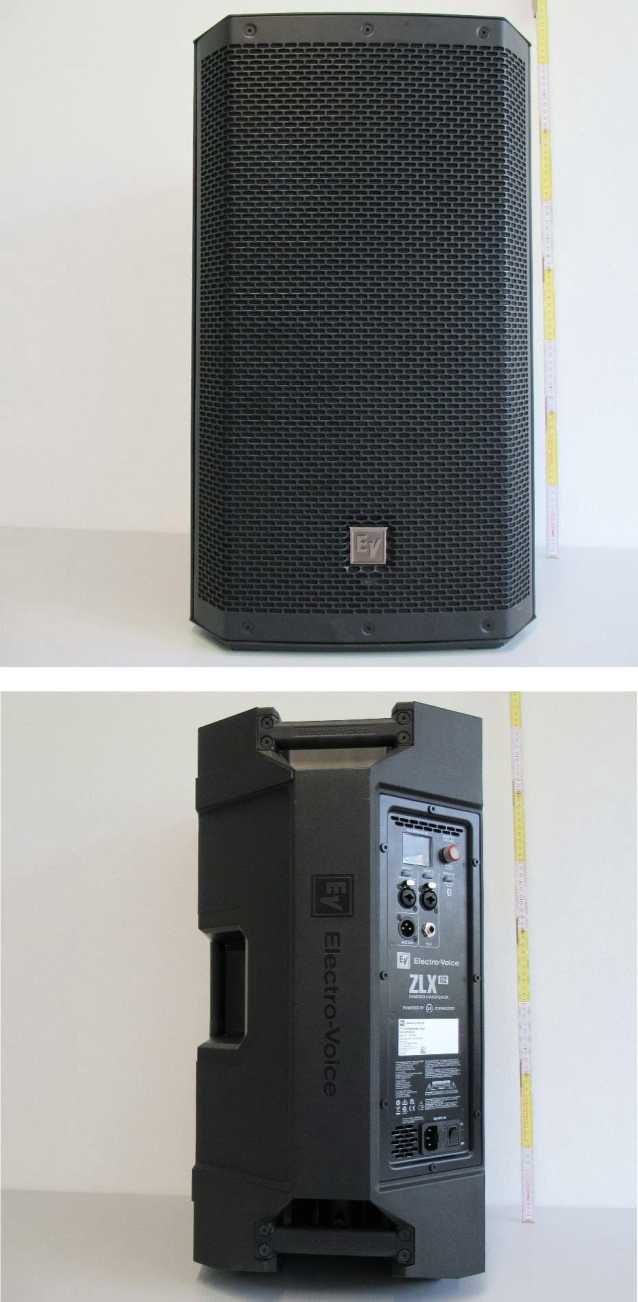
ESV-ZLXG2
Dec 21, 20232-way Powered Speaker
Equipment Class
DTS - Digital Transmission SystemESVD1
May 31, 2005Tritech Detector
Equipment Class
FDS - Part 15 Field Disturbance Sensor
ESV-RF3402
Dec 14, 2004Recessed Wireless Window or Door Magnetic Contact
Equipment Class
DSC - Part 15 Security/Remote Control Transmitter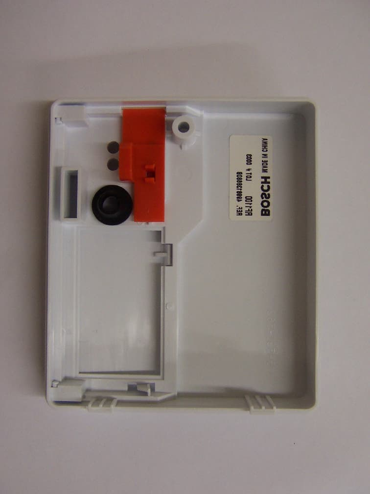
ESV-RF1100
Aug 04, 2004Wireless Glass Break Transmitter
Equipment Class
DSC - Part 15 Security/Remote Control Transmitter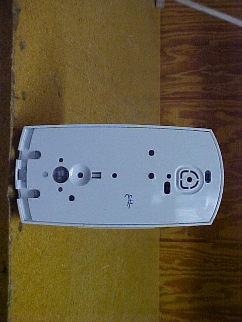
ESV850
Oct 26, 2003PIR/Microwave Intrusion Detector
Equipment Class
FDS - Part 15 Field Disturbance Sensor