EUGDJ-X2000TWide Range Scanning Receiver
USA Alinco Branch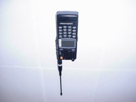
Click to zoom
Application Details
- Equipment Class
- CSR - Scanning Receiver
- Date of Grant
- Nov 19, 2000
- Application Purpose
- Original Equipment
- Date of Application
- Nov 19, 2000
- Equipment Note
- Wide Range Scanning Receiver
- Frequency Range
- 894.00000000 - 960.00000000
- Company
- USA Alinco Branch
- Country
- United States
Documents & Files
Document Text
Text extracted from the exhibit documents filed with the FCC. Open a document above to read the original.
Users Manual
COMPANY NAME: ALINCO, INC. EUT: DJ-X2000T WORK ORDER NUMBER: 2000448 FCC ID: EUG DJ-X2000T Scanning Receiver Certification Report Page 57 of 65 APPENDIX G: INSTRUCTION MANUAL WIDE RANGE SCANNING RECEIVER Instruction Manual Thank you for purchasing the ALINCO receiver. The DJ-X2000 instruction manual contains important safety and operating instructions. Read this manual carefully before using the product. DJ-X2000 I N T E L L I G E N T R E C E I V E R DJ-X2 3 6 9 8 0 5 2 1 4 C L R E N T MIC S C N R F C H E L P 7 1 Features The Alinco DJ-X2000 is a professional multifunctional receiver which covers a wide band of radio media from the low-frequency band (LF) to ultrahigh- frequency (UHF) band. It has the following features. 1. Wide frequency rangeThe DJ-X2000 covers the wide frequency range from 0.1 to 2149.999950 MHz. 2. Three basic modesThe DJ-X2000 has three basic modes: Dual VFO, Memory (MR), and Scan Programming (PMS). The modes can be switched by one-touch operation. 3. Memory capacityMemory function allows you to program the frequencies up to 2000 channels. (40 ch ×50 banks) 4. ScanningVarious kinds of scan are available: Program scan (PMS), Memory scan, Mode-select scan, VFO scan, VFO-linked scan, and Priority scan. 5. 20 scan programsThe PMS mode has a total of 20 programmable bands. 6. Channel scopeThe search function checks frequencies in the set frequency steps and displays signals within a 40- channel or 7-channel range at once. 7. Battery-save functionThe battery-save function automatically saves on battery power whenever keys are not used or a signal is not picked up for a certain amount of time. 8. CloningYou can copy the settings stored in memory from one DJ-X2000 to another. Moreover, you can connect the DJ-X2000 with a personal computer to copy the settings. 9. All mode receptionYou can select a signal mode from AM, NFM, WFM, LSB, USB, CW, and AUTO. When AUTO is selected, the DJ-X2000 automatically determines the most suitable signal mode for currently receiving frequency. 10. Channel stepChannel step is selectable from 23 fixed steps, or you can set any step between 50 Hz - 500 kHz. In addition, the DJ-X2000 determines the most suitable channel step for currently receiving frequency when AUTO is selected. 2 11. Frequency editingYou can copy the content of one memory channel to another, or rename memory channels. 12. TransweeperThe DJ-X2000 detects the listening microphone which transmits a radio wave. If a listening microphone is found, the DJ-X2000 will alert you with a display and warning sound. 13. Recording functionThe DJ-X2000 records the sound of currently receiving signal or from the microphone, and replays it. The maximum recording time is 160 minutes. 14. DescramblerThe DJ-X2000 can return scrambled voice transmission to a normal voice reception. 15. Flash tuneIf there are signals around the DJ-X2000, it tunes in the strongest frequency in a flash. 16. RF checkerThis function allows you to use the DJ-X2000 as a radio frequency checker. 17. Electric field strength meterThe DJ-X2000 can measure the electric field strength and indicate it on the display. 18. Directional microphoneThe built-in microphone picks up the sound and amplifies it. 19. Transceiver functionThe DJ-X2000 can be used as a transceiver or transmitter using 250 MHz band. 20. Receiving FM radio in stereoThe DJ-X2000 receives FM radio in stereo. 21. CTCSS decoderThe DJ-X2000 decodes the CTCSS signal. 22. A/B squelchUsing this function, the squelch unmutes only when the DJ-X2000 fails to receive a modulation signal of 2300 Hz. 23. Help-navigatorThe Help-navigator shows how to use each function of the DJ-X2000 on the display. Moreover, you can jump to the setting display of currently displayed function from the help menu, and execute the function. 24. Exceedingly sensitive antenna for HF and MF Newly developed antenna is attached. 25. DC switching power supplyDC switching power supply saves on the battery power. 26. 2-level attenuatorHigh (20 dB) and Low (10 dB) attenuators are available. 3 Contens 1. Before use00 1.1 Unpacking the receiver00 1.2 Precautions in use00 1.3 Names of parts and their funciotns00 1.3.1 Top, front and left side panels00 1.3.2 Rear and right panels00 1.3.3 Display00 1.3.4 Key pad00 1.4 Setting up the DJ-X200000 1.4.1 Attaching the antenna00 1.4.2 Attaching the belt clip00 1.4.3 Attaching the wrist strap00 1.5 About the batteries00 1.5.1 Attaching the battery pack00 1.5.2 About the battery pack00 1.5.3 Ni-Cd batterypack00 1.5.4 Battery low alarm00 2. Basic operations00 2.1 POWER switch00 2.2 Volume control00 2.3 Squelch control00 2.4 Setting frequency00 2.5 Switching frequency band00 2.6 Copying frequencies from one band to the other00 2.7 Scanning00 2.8 Sarching(Channel Scope)00 2.9 Monitoring(Squelch OFF)00 2.10 Turning backlight ON/OFF00 2.10.1 Turning backlight ON/OFF manually00 2.10.2 Turning backlight ON/OFF based on the setting00 2.11 Turning beep ON/OFF00 2.12 Locking/Unlocking00 2.13 Setting the clock00 2.13.1 Setting the OFF timer00 4 2.13.2 Setting the ON timer00 2.14 Basic modes00 2.14.1 VFO mode00 2.14.2 PMS mode00 2.14.3 MR mode00 2.15 Using HELP menu00 3. Other Useful Functions00 3.1 Functions common to all modes00 3.1.1 Selecting a signal mode00 3.1.2 Setting the frequency step00 3.1.3 Attenuating interference from other cannels(ATT)00 3.1.4 Battery Save00 3.1.5 Copying data between two receivers(CLONE)00 3.1.6 Selecting a communication speed00 3.1.7 Selecting a language mode00 3.1.8 Field-strength meter00 3.1.9 Displaying battery voltage00 3.1.10 Setting the reception tone00 3.1.11 Selecting the BELL mode00 3.1.12 Changing the initial message00 3.1.13 Resetting the receiver00 3.1.14 Tuning in frequencies in the PMS/MR modes(M.TUNE)00 3.1.15 Setting scan resume condition(SCAN MODE)00 3.1.16 Setting scan signal level00 3.1.17 Setting the scanning pause period00 3.1.18 Turning the priority function ON/OFF00 3.1.19 Selecting a priority option00 3.1.20 Setting prio…
Text truncated - open the document above for the full version.
Attestation Statements
COMPANY NAME: ALINCO, INC. EUT: DJ-X2000T WORK ORDER NUMBER: 2000448 FCC ID: EUG DJ-X2000T Scanning Receiver Certification Report Page 62 of 65 APPENDIX I: ATTESTATION LETTER COMPANY NAME: ALINCO, INC. EUT: DJ-X2000T WORK ORDER NUMBER: 2000448 FCC ID: EUG DJ-X2000T Scanning Receiver Certification Report Page 63 of 65
Cover Letter(s)
COMPANY NAME: ALINCO, INC. EUT: DJ-X2000T WORK ORDER NUMBER: 2000448 FCC ID: EUG DJ-X2000T Scanning Receiver Certification Report Page 64 of 65 APPENDIX J: AGENT AUTHORIZATION LETTER COMPANY NAME: ALINCO, INC. EUT: DJ-X2000T WORK ORDER NUMBER: 2000448 FCC ID: EUG DJ-X2000T Scanning Receiver Certification Report Page 65 of 65
External Photos
COMPANY NAME: ALINCO, INC. EUT: DJ-X2000T WORK ORDER NUMBER: 2000448 FCC ID: EUG DJ-X2000T Scanning Receiver Certification Report Page 33 of 65 APPENDIX E: EXTERNAL PHOTOS COMPANY NAME: ALINCO, INC. EUT: DJ-X2000T WORK ORDER NUMBER: 2000448 FCC ID: EUG DJ-X2000T Scanning Receiver Certification Report Page 34 of 65 Front View of EUT Rear View of EUT COMPANY NAME: ALINCO, INC. EUT: DJ-X2000T WORK ORDER NUMBER: 2000448 FCC ID: EUG DJ-X2000T Scanning Receiver Certification Report Page 35 of 65 Left Side Of EUT Right Side Of EUT
ID Label/Location Info
COMPANY NAME: ALINCO, INC. EUT: DJ-X2000T WORK ORDER NUMBER: 2000448 FCC ID: EUG DJ-X2000T Scanning Receiver Certification Report Page 28 of 65 APPENDIX A: LABEL INFORMATION COMPANY NAME: ALINCO, INC. EUT: DJ-X2000T WORK ORDER NUMBER: 2000448 FCC ID: EUG DJ-X2000T Scanning Receiver Certification Report Page 29 of 65 FIGURE 1: FCC ID FIGURE 2: LOCATION OF LABELS ON EUT Alinco, Inc. DJ-X2000T Industry Canada: XXXXX FCC ID: EUGDJ-X2000T This device complies with part 15 of the FCC Rules. Operation is subject to the following two conditions: 1) This device may not cause harmful interference, and 2) this device must accept any interference received, including interference that may cause undesired operation. WARNING: Modification of this device to receive cellular radio-telephone service signals is prohibited under FCC rules and federal law.
Test Report
Engineering and Testing for EMC and Safety Compliance 360 Herndon Parkway, Suite 1400 Herndon, VA 20170 Phone: 703-689-0368; Fax: 703-689-2056; Metro: 703-471-6441 APPLICATION FOR FCC CLASS B CERTIFICATION SCANNING RECEIVER Alinco, Inc. 438 Amapola Ave. Suite 130 Torrance, CA 90501 MODEL: DJ-X2000T FCC ID: EUG DJ-X2000T October 31, 2000 REPORT PREPARED BY: EMI Technician: E. Szrajer Administrative Writer: E. Szrajer Rhein Tech Laboratories, Inc. Document Number: 2000448 No part of this report may be reproduced without the full written approval of Rhein Tech Laboratories, Inc. This report concerns (check one): Original Grant: X Class II Change: Equipment Type: Scanning Receiver Deferred grant requested per 47 CFR 0.457 (d) (1) (ii)? Yes: No: X If yes, defer until: Date Company name agrees to notify the Commission by: (date) of the intended date of announcement of the product so that the grant can be issued on that date. Transition Rules Request per 15.37? Yes: No: X If no, assumed Part 15, subpart B for unintentional radiators - the new 47 CFR [10-1-90 Edition] provision.. COMPANY NAME: ALINCO, INC. EUT: DJ-X2000T WORK ORDER NUMBER: 2000448 FCC ID: EUG DJ-X2000T Scanning Receiver Certification Report Page 3 of 65 TABLE OF CONTENTS 1.0 GENERAL INFORMATION....................................................................................................................................5 1.1 STANDARDS REFERENCED..........................................................................................................................................5 1.2 BASIC INFORMATION ON THE EUT............................................................................................................................5 1.3 MODIFICATIONS.............................................................................................................................................................6 1.4 RELATED SUBMITTAL(S)/GRANT(S)..........................................................................................................................6 1.5 TEST METHODOLOGY...................................................................................................................................................6 1.6 TEST FACILITY...............................................................................................................................................................6 2.0 SYSTEM TEST CONFIGURATION.....................................................................................................................7 2.1 JUSTIFICATION...............................................................................................................................................................7 2.2 EXERCISING THE EUT..................................................................................................................................................7 2.3 TEST SYSTEM DETAILS................................................................................................................................................7 2.4 TEST SYSTEM CONFIGURATION PHOTOGRAPH.....................................................................................................8 2.5 EMISSIONS EQUIPMENT LIST......................................................................................................................................9 2.6 TEST METHODOLOGY.................................................................................................................................................10 3.0 CONDUCTED EMISSION DATA........................................................................................................................11 TABLE 1: Conducted Emissions: (69 MHz).................................................................................................................11 TABLE 2: Conducted Emissions: (129 MHz)...............................................................................................................12 TABLE 3: Conducted Emissions: (195 MHz)...............................................................................................................13 TABLE 4: Conducted Emissions: (355 MHz)...............................................................................................................14 TABLE 5: Conducted Emissions: (685 MHz)...............................................................................................................15 TABLE 6: Conducted Emissions: (900 MHz)...............................................................................................................16 4.0 RADIATED EMISSION DATA.............................................................................................................................17 TABLE 7: Radiated Emissions: (30 MHz)....................................................................................................................17 TABLE 8: Radiated Emissions: (69 MHz)....................................................................................................................17 TABLE 9: Radiated Emissions: (108 MHz)..................................................................................................................18 TABLE 10: Radiated Emissions: (129 MHz)................................................................................................................18 TABLE 11: Radiated Emissions: (150 MHz)................................................................................................................19 TABLE 12: Radiated Emissions: (195 MHz)................................................................................................................19 TABLE 13: Radiated Emissions: (240 MHz)................................................................................................................20 TABLE 14: Radiated Emissions: (355 MHz)..........................................................…
Text truncated - open the document above for the full version.
Test Report
COMPANY NAME: ALINCO, INC. EUT: DJ-X2000T W ORK ORDER NUMBER: 2000448 FCC ID: EUG DJ-X2000T Scanning Receiver Certification Report Page 24 of 65 4.1 38dB Rejection Test A signal generator was connected to the receiver under test, and the output of the receiver was connected to an audio analyzer. A FM signal was applied to the receiver antenna input with a 1kHz tone modulated at 8 kHz deviation, and adjusted with the audio analyzer to produce a 12 dB SINAD. This was done across the receiver bands to determine a reference level. The reference level used was that with the highest sensitivity in all of the bands. The output of the signal generator was then adjusted to a level 40 dB above the reference level established and set to a low, medium and high frequency in both the mobile and base cellular bands. (Mobile = 824.04 MHz through 848.97 MHz, Base = 869.04 MHz through 893. 97 MHz). The squelch of the receiver was then set to a minimum threshold level and scanning began from the lowest to the highest channel. Whenever the receiver stopped and “un-squelched” that frequency was noted as a response. After all the frequencies of responses were noted, the signal generator was set to measure the sensitivity at each of these response frequencies. This measurement was the reference sensitivity for the particular received frequency measured. The audio analyzer measurement was used to measure the 12 dB SINAD and that is the spurious value. The difference between the reference sensitivity and the spurious value is the rejection ratio and must be at least 38 dB. Frequencies used on the Signal Generator were 824.04, 836.50, 848.97 MHz for the Mobile and 869.04, 887.73, 893.97 MHz for the Base. The DJ-X2000T unit reference level used was –50 dBm from the signal generator, this was determined from the highest sensitivity from 930 MHz at –90.0 dBm measurement of 12dB SINAD. The DJ-X2000T unit was scanned from 30 - 960 MHz for all channels (manufacturers spec.). Signals that were noted as responses were checked with the signal generator off and if they still existed as a response were determined as ambient signals and removed from the response list. There was one signal available for the 38 dB rejection test requirements. HP 8648C Signal Generator (1kHz tone/8kHz FM deviation) Antenna Input EUT Audio out HP 8903B Audio Analyzer External 13VDC power adapter COMPANY NAME: ALINCO, INC. EUT: DJ-X2000T W ORK ORDER NUMBER: 2000448 FCC ID: EUG DJ-X2000T Scanning Receiver Certification Report Page 25 of 65 38dB Rejection Cellular Band (869.04 - 893.97) MHz Date: 10/31/00 Temp: 74°°F Humidity: 33% Model: DJ-X2000T Table 1 Frequency Injected 869.04MHz Frequency Detected (MHz) Level 12dB SINAD at 869.04MHz Level 12dB at frequency detected Rejection Margin No Frequencies Detected N/A N/A N/A N/A Table 2 Frequency Injected 887.73MHz Frequency Detected (MHz) Level 12dB SINAD at 887.73MHz Level 12dB at frequency detected Rejection Margin No Frequencies Detected N/A N/A N/A N/A Table 3 Frequency Injected 893.97MHz Frequency Detected (MHz) Level 12dB SINAD at 893.97MHz Level 12dB at frequency detected Rejection Margin No Frequencies Detected N/A N/A N/A N/A COMPANY NAME: ALINCO, INC. EUT: DJ-X2000T W ORK ORDER NUMBER: 2000448 FCC ID: EUG DJ-X2000T Scanning Receiver Certification Report Page 26 of 65 38dB Rejection Mobile Band (824.04- 848.97) MHz Date: 10/31/00 Temp: 74°°F Humidity: 33% Model: DJ-X2000T Table 1 Frequency Injected 824.04MHz Frequency Detected (MHz) Level 12dB SINAD at 824.04MHz Level 12dB at frequency detected Rejection Margin No Frequencies Detected N/A N/A N/A N/A Table 2 Frequency Injected 836.50MHz Frequency Detected (MHz) Level 12dB SINAD at 836.50MHz Level 12dB at frequency detected Rejection Margin 719.00 -57dBm -101dBm 44dB 6dB Table 3 Frequency Injected 848.97MHz Frequency Detected (MHz) Level 12dB SINAD at 848.97MHz Level 12dB at frequency detected Rejection Margin No Frequencies Detected N/A N/A N/A N/A
Test Setup Photos
COMPANY NAME: ALINCO, INC. EUT: DJ-X2000T WORK ORDER NUMBER: 2000448 FCC ID: EUG DJ-X2000T Scanning Receiver Certification Report Page 58 of 65 APPENDIX H: TEST PICTURES COMPANY NAME: ALINCO, INC. EUT: DJ-X2000T WORK ORDER NUMBER: 2000448 FCC ID: EUG DJ-X2000T Scanning Receiver Certification Report Page 59 of 65 Conducted Configuration Photographs COMPANY NAME: ALINCO, INC. EUT: DJ-X2000T WORK ORDER NUMBER: 2000448 FCC ID: EUG DJ-X2000T Scanning Receiver Certification Report Page 60 of 65 Radiated Configuration Photographs COMPANY NAME: ALINCO, INC. EUT: DJ-X2000T WORK ORDER NUMBER: 2000448 FCC ID: EUG DJ-X2000T Scanning Receiver Certification Report Page 61 of 65 38dB Rejection Configuration Photograph
Test Setup Photos
COMPANY NAME: ALINCO, INC. EUT: DJ-X2000T WORK ORDER NUMBER: 2000448 FCC ID: EUG DJ-X2000T Scanning Receiver Certification Report Page 8 of 65 2.4 TEST SYSTEM CONFIGURATION PHOTOGRAPH
Contact Information
Applicant
Katsumi Nakata(Branch Manager)
Technical Contact
Rhein Tech LaboratoriesDesmond Fraser
[email protected]703 689 0368
360 Herndon Drive · Herndon, Virginia · United States
Test Firm
Rhein Tech Laboratories, Inc.Rick McMurray
Technical Specifications
| # | Rule Parts | Frequency Range | Power Output |
|---|---|---|---|
| 5 | 15B | 894 MHz - 960 MHz | - |
Other Applications from USA Alinco Branch
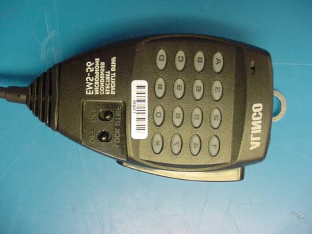
EUGDR-235T
Aug 14, 2002VHF Scanning Receiver
Equipment Class
CSR - Scanning Receiver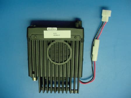
EUGDR-435T
Dec 14, 2000Scanning Transceiver
Equipment Class
CSR - Scanning Receiver
EUGDR-135T
Aug 08, 2000VHF Scanning Receiver
Equipment Class
CSR - Scanning ReceiverEUGDJ-196T
Jul 18, 2000VHF-FM Amature Transceiver with Scanning Receiver
Equipment Class
CSR - Scanning Receiver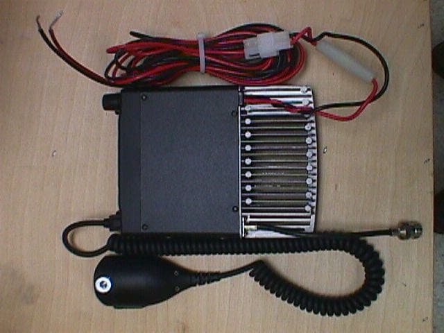
EUGDR-605T
May 03, 2000DR-605T
Equipment Class
CSR - Scanning Receiver