EZSAESTG34Security/Remote Control Transmitter
Voxx Electronics Corporation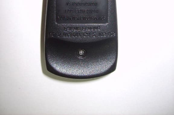
Click to zoom
Application Details
- Equipment Class
- DSS - Part 15 Spread Spectrum Transmitter
- Date of Grant
- Oct 23, 2007
- Application Purpose
- Original Equipment
- Date of Application
- Oct 23, 2007
- Equipment Note
- Security/Remote Control Transmitter
- Frequency Range
- 909.54600000 - 918.78000000
- Company
- Voxx Electronics Corporation
- Country
- United States
Documents & Files
Document Text
Text extracted from the exhibit documents filed with the FCC. Open a document above to read the original.
Users Manual
Tous droits réservés © Astroflex Electronics 2007 Novembre 2007 UBRSS5224 NOS DE BREVETS CAN 1.130.426 É.-U. 4.345.554 - 5.614.883 - 5.617.819 - 5.673.017 ET AUTRES BREVETS EN INSTANCE DÉMARREUR À DISTANCE À COMMUNICATION BIDIRECTIONNELLE ® MANUEL DE L’USAGER MODÈLE RSS-5224 Conçu pour tout véhicule automobile à essence, diesel ou hybride. 2 voies (XRT) 1 voie (Compagnon) (ENGLISH ON REVERSE) V EUILLEZ CONSULTER LES RÈGLES DE SÉCURITÉ AVANT L ’ UTILISATION DE CE PRODUIT . C ERTAINES FONCTIONS PEUVENT NÉCESSITER DU MATÉRIEL SUPPLÉMENTAIRE NON INCLUS . RÉGLEMENTATION Ce dispositif satisfait aux exigences spécifications standards pour la radio RSS 210 d’Industrie Canada (IC). Son utilisation est autorisée seulement sur une base de non-brouillage et de non-protection; en d’autres termes, ce dispositif ne doit pas être utilisé s’il est établi qu’il représente une source de brouillage nuisible pour les services autorisés par IC. Par ailleur s, l’utilisateur de ce dispositif doit être prêt à accepter tout brouillage radioélectrique reçu, même si ce brouillage est susceptible de compromettre le fonctionnement du dispositif. Ce dispositif est conforme aux dispositions de la partie 15 des règlements de la Commission fédérale sur les communications (FCC). Son utilisation est assujettie aux deux conditions suivantes : (1) ce dispositif ne doit pas être à l'origine de brouillage nuisible, et (2) ce dispositif doit accepter le brouillage qui peut en entraîner un fonctionnement indésirable. Ce matériel a fait l'objet d'essais et respecte les limites imposées aux dispositifs numériques appartenant à la classe B, conformément à la partie 15 des règlements de la FCC. Ces limites ont été conçues pour assurer une protection raisonnable contre les brouillages nuisibles à l'intérieur d'une résidence. Ce matériel produit, utilise et peut émettre des radiofréquence s et, s'il n'est pas installé et utilisé conformément aux instru ctions du manuel d'installation et de l’usager, peut être à l'ori gine de brouillage nuisible aux appareils de communication exploitant les radiofréquences. Toutefois, il n'est pas garanti qu'aucun brouillage ne se produira dans une installation en particulier. Aussi, dans l'éventualité où ce matériel venait à causer du brouillage nuisible au niveau des appareils radio ou aux téléviseurs, ce que l'on peut vérifier en mettant l’appareil hors fonction, puis en fonction, il est recommandé que l'utilisateur essaie de corriger la situation en prenant une ou plusieur s des mesures suivantes : réorienter l'antenne réceptrice ou en changer l'emplacement; éloigner le matériel du récepteur; brancher le matériel dans une prise appartenant à un circuit différent du circuit auquel est branché le récepteur; consulter le concessionnaire ou un technicien qualifié en matière de radiotélévision. Avertissement: Tout changement ou toute modification qui ne font pas l'objet d'une autorisation expresse du <fabricant> peuvent annuler le droit de l'usager d'utiliser l'appareil. ELECTRONICS 188 St-François-Xavier Delson, Qc Canada J5B 1X9 www.astroflex.com 3 MERCI D'AVOIR CHOISI UN DÉMARREUR À DISTANCE ASTROSTART! Comme vous, la compagnie Astroflex est soucieuse de l’environnement. C’est pourquoi nous vous suggérons d’utiliser le temps de fonctionnement de deux minutes lors du démarrage à distance de votre véhicule pour réchauffer les fluides du moteur. Nous profitons de l’occasion pour vous inviter à bien faire dégivrer les vitres de votre véhicule et de le nettoyer convenablement avant de prendre la route. Les igloos mobiles sont très dangereux! Nous vous souhaitons une excellente route avec votre démarreur à distance! G UIDE DE L ' USAGER POUR COMMANDE À DISTANCE RSS-5224. Le RSS-5224 est une commande de démarrage à distance à communication bidirectionnelle, c'est-à-dire qu'elle à la capacité de communiquer dans les deux sens (télécommande XRT) et, par conséquent, de retourner un accusé de réception à la télécommande et/ou de communiquer l'état du véhicule. Un kit d’alarme optionnel (No. de pièce # ALA-OP) peut être ajouté. Le cas échéant, ce dernier se verra attribuer les fonctions relatives au système de sécurité décrites dans le présent manuel. Les fonctions relatives au système de sécurité décrites dans le présent manuel s’appliquent seulement à la commande a distance à laquelle on a ajouté un kit d’alarme. Le RSS-5224 vous offre des fonctions de télé-déverrouillage vous permettant de commander les verrous de portière ainsi que l'accès au coffre arrière. Ces fonctions sont optionnelles et peuvent nécessiter du matériel et des raccordements lors de l'installation. Table des matières RÈGLES DE SÉCURITÉ _____________________________________________________________________________ 4 S ÉQUENCE DE SÉCURITÉ POUR VÉHICULES À BOÎTE DE VITESSES MANUELLE ------------------------------------------------------------------4 P RÉPARATION DU SYSTÈME ------------------------------------------------------------------------------------------------------------------------------ 5 LA TÉLÉCOMMANDE 2 VOIES XRT ___________________________________________________________________ 6 T ÉLÉ - AVERTISSEUR ------------------------------------------------------------------------------------------------------------------------------ ----------8 LA TÉLÉCOMMANDE 1 VOIE COMPAGNON ____________________________________________________________ 9 S ÉLECTION DU CANAL DE TRANSMISSION --------------------------------------------------------------------------------------------------------------9 R EMPLACEMENT DES PILES ------------------------------------------------------------------------------------------------------------------------------ -9 TABLEAU DES COMMANDES ______________________________________________________________________ 10 L ES COMMANDES DE DÉMARRAGE -------------------------------------------------------------------------------------------------------------------- 11 S YSTÈME DE SÉCURITÉ ----------------------------------…
Text truncated - open the document above for the full version.
Cover Letter(s)
Wednesday, September 26, 2007 Chief, Equipment Approval Services Federal Communications Commission P.O. Box 358315 Pittsburgh, PA 15251-5315 Re: Request of Confidentiality Pursuant to Sections 0.457(d)(1)(ii) and 0.459 of the Commission’s Rules, the Applicant hereby requests confidential treatment of information accompanying as outlined below: Schematics Block diagram Operational description Parts List All the above for EZSAESTG34 The above materials contain trade secrets and proprietary information not customarily released to the public. The public disclosure of these matters might be harmful to the Applicant and provide unjustified benefits to its competitors. The Applicant understands that pursuant to Rule 0.457(d)(1)(ii), disclosure of this Application and all accompanying documentation will not be made before the date of the Grant for this Application. Sincerely, Minas Minassian RF Engineering Manager
ID Label/Location Info
Label does not have warnings because it is so small, see User Manual
RF Exposure Info
Prediction of MPE limit at a given distance Equation from page 18 of OET Bulletin 65, Edition 97-01 where:S = power density P = power input to the antenna G = power gain of the antenna in the direction of interest relative to an isotropic radiator R = distance to the center of radiation of the antenna 98.5dBuV/mFrom test report's measured radiated power. 3m 8.4E-02V=10 ((35.5-120/120) 0.002106285W= ((V x 3m/5.5) 2 ) Maximum peak output power --Radiated:0.0021(W) Antenna gain(typical):0.00(dBi) Maximum antenna gain:1.00(numeric) Prediction distance:20.00(cm) Prediction frequency:909.55(MHz) Limit from table below:0.606(mW/cm^2) Power density at prediction frequency:0.0004(mW/cm^2) EUT complies 2 4R PG S π = FCC/LSGAC Local Official’s Guide to RF A LOCAL GOVERNMENT OFFICIAL'S GUIDE TO TRANSMITTING ANTENNA RF EMISSION SAFETY: RULES, PROCEDURES, AND PRACTICAL GUIDANCE
Test Report
Nemko USA, Inc. 11696 Sorrento Valley Rd., Suite F San Diego, CA 92121-1024 Phone (858) 755-5525 Fax (858) 452-1810 FCC Part 15 Subpart C, 15.247 : 23/10/2007 Certification Test Report: 2007 097241-1 FCC Project number: 7241-1 Equipment Under Test (EUT): Keyfob Model: TST-5223, TST-5224 FCC ID: EZSAESTG34 IC: 1513A-ASTG34 In Accordance With: FCC Part 15 Subpart C, 15.247 RSS-210, Issue 7 June 2007 For: Directed Electronics, Inc. One Viper Way Vista, CA 92081 USA Tested By: Nemko USA Inc. 11696 Sorrento Valley Road, Suite F San Diego, CA 92121 Authorized By: FR Fleury FR Fleury, Manager Date: SEPTEMBER 21, 2007 Total Number of Pages: 34 Nemko USA, Inc. 11696 Sorrento Valley Road, Suite F, San Diego, CA 92121 Phone (858) 755-5525 Fax (858) 452-1810 IC: 1513A-AETG34 Report Number: 2007 097241-1 FCC FCC ID: EZSAESTG34 Specification: FCC Part 15 Subpart C, 15.247 Page 2 of 34 2.1. Section 1. Summary of Test Results General All measurements are traceable to national standards These tests were conducted on a sample of the equipment for the purpose of demonstrating compliance with Part 15; Subpart C and RSS-210, Issue 7 June 2007. Radiated tests were conducted is accordance with ANSI C63.4-2003. Radiated emissions are made on an open area test site. A description of the test facility is on file with the FCC and IC. The assessment summary is as follows: Apparatus Assessed: Keyfob TST-5223, TST-5224 Specifications: FCC Part 15 Subpart C, 15.247 RSS-210, Issue 7 June 2007 Date Received in Laboratory: September 21, 2007 Compliance Status: Complies Exclusions: None Non-compliances: None Nemko USA, Inc. 11696 Sorrento Valley Road, Suite F, San Diego, CA 92121 Phone (858) 755-5525 Fax (858) 452-1810 IC: 1513A-AETG34 Report Number: 2007 097241-1 FCC FCC ID: EZSAESTG34 Specification: FCC Part 15 Subpart C, 15.247 Page 3 of 34 Report Release History: REVISION DATE COMMENTS - September 21, 2007 Prepared By: Alan Laudani - September 21, 2007 Initial Release: F. Fleury Note that the results contained in this report relate only to the items tested and were obtained in the period between the date of initial receipt of samples and the date of issue of the report. This test report has been completed in accordance with the requirements of ISO/IEC 17025. Nemko USA Inc. authorizes the applicant to reproduce this report provided it is reproduced in its entirety and for use by the company’s employees only. Any use which a third party makes of this report, or any reliance on or decisions to be made based on it, are the responsibility of such third parties. Nemko USA Inc. accepts no responsibility for damages, if any, suffered by any third party as a result of decisions made or actions based on this report. TESTED BY: Date: September 21, 2007 Alan Laudani, EMC Test Engineer Nemko USA, Inc. 11696 Sorrento Valley Road, Suite F, San Diego, CA 92121 Phone (858) 755-5525 Fax (858) 452-1810 IC: 1513A-AETG34 Report Number: 2007 097241-1 FCC FCC ID: EZSAESTG34 Specification: FCC Part 15 Subpart C, 15.247 Page 4 of 34 TABLE OF CONTENTS 2.1. Section 1. Summary of Test Results.......................................................................2 Section 2: Equipment Under Test..........................................................................................5 2.1 Product Identification..............................................................................................................5 2.2 Technical Specifications of the EUT.........................................................................................5 Section 3: Test Conditions......................................................................................................6 3.1 Specifications.........................................................................................................................6 3.2 Deviations From Laboratory Test Procedures...........................................................................6 3.3 Test Environment...................................................................................................................6 3.4 Test Equipment......................................................................................................................7 Section 4: Observations...........................................................................................................8 4.1 Modifications Performed During Assessment............................................................................8 4.2 Record Of Technical Judgements............................................................................................8 4.3 EUT Parameters Affecting Compliance....................................................................................8 4.4 Test Deleted...........................................................................................................................8 4.5 Additional Observations..........................................................................................................8 Section 5: Results Summary...................................................................................................9 5.1 Test Results...........................................................................................................................9 Appendix A: Test Results......................................................................................................10 20 dB Bandwidth..............................................................................................................................10 Time of Occupancy...........................................................................................................................14 Channel Separation..........................................................................................................................17 Frequency Plan................................................................................................................................19 Number of Hopping Cha…
Text truncated - open the document above for the full version.
Test Setup Photos
Radiated Emissions Setup: Relative Emissions Setup: Number of Hopping Frequencies, Channel Separation, ETC. where the actual amplitude is not measured.
Contact Information
Applicant
Joseph A. Santavicca(SVP of Engineering)
Technical Contact
Directed ElectronicsMinas Minassian
[email protected](760) 598-6200
1 Viper Way · Vista, California · United States
Non-Technical Contact
Directed ElectronicsMinas Minassian
[email protected](760) 598-6200
Test Firm
Nemko USA, Inc.Rhonda Saxon
Technical Specifications
| # | Rule Parts | Frequency Range | Power Output |
|---|---|---|---|
| 1 | 15C | 909.546 MHz - 918.78 MHz | 2.10 mW |
Other Applications from Voxx Electronics Corporation
EZS2403VD
Jan 08, 2026BT/NFC Reader
Equipment Class
JAB - Part 15 Class B Digital DeviceEZS6214T
Dec 02, 2024Transceiver
Equipment Class
DSR - Part 15 Remote Control/Security Device Transceiver
EZS1412VD
Jul 19, 2024KiB Ekey
Equipment Class
DTS - Digital Transmission System
EZS8812
Dec 10, 20228812
Equipment Class
DTS - Digital Transmission System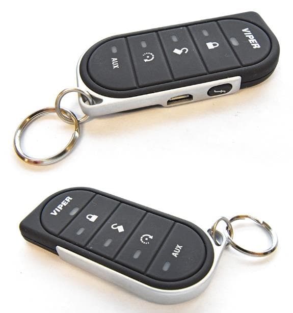
EZSG7857
Mar 22, 2021915MHz Remote Start Handheld Key fob
Equipment Class
DSS - Part 15 Spread Spectrum Transmitter