EZSDEI3807915Mhz spread spectrum 25 channels HHU
Voxx Electronics Corporation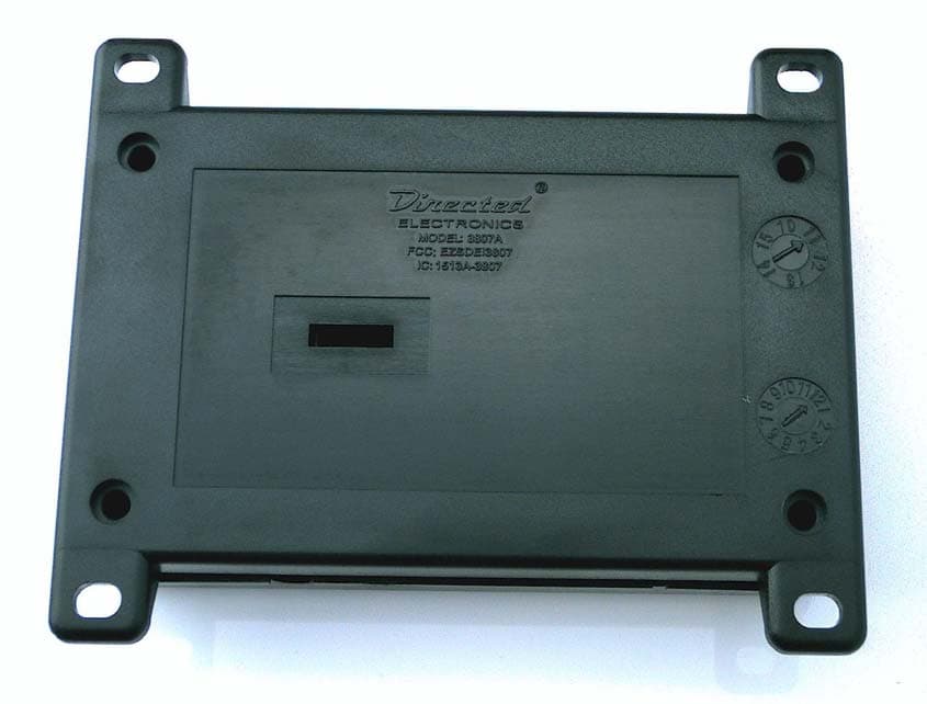
Click to zoom
Application Details
- Equipment Class
- DSS - Part 15 Spread Spectrum Transmitter
- Date of Grant
- Dec 18, 2011
- Application Purpose
- Original Equipment
- Date of Application
- Dec 16, 2011
- Equipment Note
- 915Mhz spread spectrum 25 channels HHU
- Frequency Range
- 909.44000000 - 918.50000000
- Company
- Voxx Electronics Corporation
- Country
- United States
Documents & Files
Document Text
Text extracted from the exhibit documents filed with the FCC. Open a document above to read the original.
Users Manual
© 2011 Directed Electronics. All rights Reserved.1 Quick Reference Install Guide 3807A Automate Security System LIGHT FLASH POLAR ITY (10A (MAXIM UM) FUS E JUMPER) BLACK (-) Chassis Ground RED (+) 12V Constant Power WHITE/BLACK Light Flash Relay Isolation wire (87a) WHITE (+/-) Light Flash Relay Output (30) YELLOW (+) Ignition Input RED/WHITE (-) 200 mA Trunk Pop Output BROWN (-) 200 mA Horn/Siren Output ORANGE (-) 500mA Ground When Armed Output VIOLET (+) Door Trigger Input GREEN (-) Door Trigger Input (Red plug) Programmer Port BLACK/WHITE (-) 200mA Flex 2 Output (Dome Light Supervision) BLUE/BLACK (-) 200mA Flex 1 Output (2nd Unlock) GRAY (NO/NC) Hood Trigger Input BLUE (-) Trunk/MUX Trigger Input GREEN (-) 200 mA Lock Output BLUE (-) 200 mA Unlock Output ( Blue Plug) Valet/LED Port Sensor Adjustment Antenna Light Flash Polarity Jumper Detail GRAY/BLACK (+) OEM Trunk Shunt Input RED/BLACK (+/-) Disarm Defeat RED (+) Disarm Input GREEN/BLACK (+/-) Arm Defeat DARK GREEN (+) Arm Input Sensor adjustment detail (see note to right) Note Adjusting the shock sensor pot: 1 Securely mount the CPU (in a safe location) before adjusting 2 Turn the sensor adjustment clockwise to increase sensitivity, turn counterclockwise to decrease sensitivity Connection Legend 1 Required connection 2 Optional connection 3 OEM security upgrade connection 4 RF Security connection 5 Add Sensor upgrade connection Note: Replace fuse with speci ed resistor value if connecting to multiplex light circuit (paying special attention to polarity selection). 1 1 2 2 2 3 4 3 3 3 4 5 2 3 4 5 5 3 5 Chassis Ground: Connect to a scraped (bare) metal surface in the driver kick panel. NEVER connect to dash brackets or at the same point as other components. 1 12v Constant Power: Remove the in-line fuse before connecting to a wire that has (+)12v at all times. White/black: Connect to the switch side of the parking light wire in vehicles that require switch isolation during light ash This wire connects to pin 87a of the light ash relay. 1 White: Connect to the vehicle parking light wire. This wire connects to pin 30 of the light ash relay. Trunk Pop Output: Connect to the vehicles negative (-) trunk release relay or other low current device. NEVER connect directly to a motor or high current device without a relay. 1 Ignition Input: Connect to a wire that has (+)12v while the key is in the run and crank positions. 1 Horn/Siren Output: Connect to the vehicles negative (-) horn honk relay wire. It can also be used to drive the (-) wire of a siren. See Feature menu item # 7 for options. 1 Ground when Armed Output: Connect to a starter interrupt relay or other accessory that requires a ground to activate when the system is armed. 1 Door Trigger Inputs: Green: Connect to a wire that rests at (+)12v when all doors are closed and (-) ground when any door is open. OR Violet: Connect to a wire that rests at ground when all doors are closed and (+)12v when any door is open.. 2 Programming Port: The 998T Bitwriter can be connected to this port for programming feature options (chip version 2.8). SmartStart can be connected to this port to operate the system by Smartphone. OEM Trunk Shunt Input: Connect to a wire that pulses (+)12v when the OEM trunk release is activated. If armed when the trunk is opened, the shock sensor and trunk trigger will be bypassed until the trunk is closed. 2 Disarm and Disarm Defeat Inputs: Disarm Defeat Input: Connect to a wire that pulses (+)12v OR ground when ALL doors unlock (usually the passenger door motor or driver door unlock switch). Disarming will be defeated if this wire receives a pulse simultaneously with the Disarm input. This is a polarity selectable input, See Feature menu item #11 for options Disarm Input: Connect to a wire (usually the driver door motor) that pulses (+)12v when the driver door unlocks using the OEM remote to disarm the system. 2 Arm and Arm Defeat Inputs: Arm Defeat Input: Connect to a wire that pulses (+)12v OR ground when the doors lock (usually the driver door lock switch). Arming will be defeated if this wire receives a pulse simultaneously with the Arm input. This is a polarity selectable input, See Feature menu item #10 for options Arm Input: Connect to a wire (usually the driver door motor) that pulses (+)12v when the doors lock. 1 Valet/LED Port: Insert the 4pin harness connector to the combination LED/Valet pod here. 1 Lock Output: Connect to a wire that pulses ground to activate the vehicle door lock relay. (usually at the door lock switch or BCM). 1 Unlock Output: Connect to a wire that pulses ground to activate the vehicle door unlock relay. (usually at the door unlock switch or BCM). Hood Trigger Input: Connect to a wire that changes state when the hood is opened. Test the resting state of the wire when the hood is OPEN and then set the polarity accordingly. Ground = NO/12v or open = NC. See Feature menu item #6 for options 3 4 Trunk Trigger Input: Connect to a wire that goes to ground (-) when the trunk is opened or to the pre-trigger and full trigger outputs of an optional Directed Electronics dual zone sensor. 4 Flex 2 output, Dome light supervision: Connect to a wire that will turn on the dome light to illuminate the vehicles interior when disarming and turning the ignition o . 4 Flex 1 output, Factory Alarm Disarm: Connect to a wire that will disarm the factory alarm when pulsed to ground. This output will pulse when disarming and activating the Trunk Release feature for RF Security 2 4 2nd Unlock: Connect to a wire (or relay assembly) that will unlock all locked doors when installing two stage door unlocking Factory Alarm Trigger: Connect to a wire that will trigger the factory alarm system when grounded (Usually a door or trunk switch).It will pulse when the sensor full trigger zone is activated. This option is only used when installing the system as a ‘Add Sensor’ OEM security system upgrade Remote Start Report: Connect to the negative activation input of an add-…
Text truncated - open the document above for the full version.
Users Manual
© 2011 Directed Electronics. All rights Reserved.1 Quick Reference Install Guide 3808A Automate Security System LIGHT FLASH POLAR ITY (10A (MAXIM UM) FUS E JUMPER) BLACK (-) Chassis Ground RED (+) 12V Constant Power WHITE/BLACK Light Flash Relay Isolation wire (87a) WHITE (+/-) Light Flash Relay Output (30) YELLOW (+) Ignition Input RED/WHITE (-) 200 mA Trunk Pop Output BROWN (-) 200 mA Horn/Siren Output ORANGE (-) 500mA Ground When Armed Output VIOLET (+) Door Trigger Input GREEN (-) Door Trigger Input (Red plug) Programmer Port BLACK/WHITE (-) 200mA Flex 2 Output (Dome Light Supervision) BLUE/BLACK (-) 200mA Flex 1 Output (2nd Unlock) GRAY (NO/NC) Hood Trigger Input BLUE (-) Trunk/MUX Trigger Input GREEN (-) 200 mA Lock Output BLUE (-) 200 mA Unlock Output ( Blue Plug) Valet/LED Port Sensor Adjustment Antenna Light Flash Polarity Jumper Detail GRAY/BLACK (+) OEM Trunk Shunt Input RED/BLACK (+/-) Disarm Defeat RED (+) Disarm Input GREEN/BLACK (+/-) Arm Defeat DARK GREEN (+) Arm Input Sensor adjustment detail (see note to right) Note Adjusting the shock sensor pot: 1 Securely mount the CPU (in a safe location) before adjusting 2 Turn the sensor adjustment clockwise to increase sensitivity, turn counterclockwise to decrease sensitivity Connection Legend 1 Required connection 2 Optional connection 3 OEM security upgrade connection 4 RF Security connection Note: Replace fuse with speci ed resistor value if connecting to multiplex light circuit (paying special attention to polarity selection). 1 1 2 2 2 3 4 3 3 3 4 5 2 3 4 3 Chassis Ground: Connect to a scraped (bare) metal surface in the driver kick panel. NEVER connect to dash brackets or at the same point as other components. 1 12v Constant Power: Remove the in-line fuse before connecting to a wire that has (+)12v at all times. White/black: Connect to the switch side of the parking light wire in vehicles that require switch isolation during light ash This wire connects to pin 87a of the light ash relay. 1 White: Connect to the vehicle parking light wire. This wire connects to pin 30 of the light ash relay. Trunk Pop Output: Connect to the vehicles negative (-) trunk release relay or other low current device. NEVER connect directly to a motor or high current device without a relay. 1 Ignition Input: Connect to a wire that has (+)12v while the key is in the run and crank positions. 1 Horn/Siren Output: Connect to the vehicles negative (-) horn honk relay wire. It can also be used to drive the (-) wire of a siren. See Feature menu item # 7 for options. 1 Ground when Armed Output: Connect to a starter interrupt relay or other accessory that requires a ground to activate when the system is armed. 1 Door Trigger Inputs: Green: Connect to a wire that rests at (+)12v when all doors are closed and (-) ground when any door is open. OR Violet: Connect to a wire that rests at ground when all doors are closed and (+)12v when any door is open.. 2 Programming Port: The 998T Bitwriter can be connected to this port for programming feature options (chip version 2.8). SmartStart can be connected to this port to operate the system by Smartphone. OEM Trunk Shunt Input: Connect to a wire that pulses (+)12v when the OEM trunk release is activated. If armed when the trunk is opened, the shock sensor and trunk trigger will be bypassed until the trunk is closed. 2 Disarm and Disarm Defeat Inputs: Disarm Defeat Input: Connect to a wire that pulses (+)12v OR ground when ALL doors unlock (usually the passenger door motor or driver door unlock switch). Disarming will be defeated if this wire receives a pulse simultaneously with the Disarm input. This is a polarity selectable input, See Feature menu item #11 for options Disarm Input: Connect to a wire (usually the driver door motor) that pulses (+)12v when the driver door unlocks using the OEM remote to disarm the system. 2 Arm and Arm Defeat Inputs: Arm Defeat Input: Connect to a wire that pulses (+)12v OR ground when the doors lock (usually the driver door lock switch). Arming will be defeated if this wire receives a pulse simultaneously with the Arm input. This is a polarity selectable input, See Feature menu item #10 for options Arm Input: Connect to a wire (usually the driver door motor) that pulses (+)12v when the doors lock. 1 Valet/LED Port: Insert the 4pin harness connector to the combination LED/Valet pod here. 1 Lock Output: Connect to a wire that pulses ground to activate the vehicle door lock relay. (usually at the door lock switch or BCM). 1 Unlock Output: Connect to a wire that pulses ground to activate the vehicle door unlock relay. (usually at the door unlock switch or BCM). Hood Trigger Input: Connect to a wire that changes state when the hood is opened. Test the resting state of the wire when the hood is OPEN and then set the polarity accordingly. Ground = NO/12v or open = NC. See Feature menu item #6 for options 3 4 Trunk Trigger Input: Connect to a wire that goes to ground (-) when the trunk is opened or to the pre-trigger and full trigger outputs of an optional Directed Electronics dual zone sensor. 4 Flex 2 output, Dome light supervision: Connect to a wire that will turn on the dome light to illuminate the vehicles interior when disarming and turning the ignition o . 4 Flex 1 output, Factory Alarm Disarm: Connect to a wire that will disarm the factory alarm when pulsed to ground. This output will pulse when disarming and activating the Trunk Release feature for RF Security 2 2 4 2nd Unlock: Connect to a wire (or relay assembly) that will unlock all locked doors when installing two stage door unlocking Factory Alarm Trigger: Connect to a wire that will trigger the factory alarm system when grounded (Usually a door or trunk switch).It will pulse when the sensor full trigger zone is activated. Remote Start Report: Connect to the negative activation input of an add-on remote starter or other low current device. NEVER connect directly to a motor or high current device without a relay. Additional fu…
Text truncated - open the document above for the full version.
Cover Letter(s)
October 12, 2011 Nemko Canada Inc 303 River Road Ottawa, Ontario, Canada K1V 1H2 Attn: Director of Certification FCC ID: EZSDEI3807 Authority to Act as Agent On our behalf, I appoint Alan Laudani of Nemko USA Inc., 2210 Faraday Ave, STE 150, Carlsbad, CA, USA to act as our agent in the preparation of this application for equipment certification. I certify that submitted documents properly describe the device or system for which equipment certification is sought. I also certify that each unit manufactured, imported or marketed, as defined in Federal Communication Commission’s regulations will have affixed to it a label identical to that submitted for approval with this application. For instances where our authorized agent signs the application for certification on our behalf, I acknowledge that all responsibility for complying with the terms and conditions for certification, as specified by Nemko USA Inc, still resides with Minas Minassian, DEI Headquarters,Inc,, 1Viper way, Vista CA 92081, USA. Minas Minassian DEI Headquarters,Inc, 1Viper way Vista CA 92081 USA This appointment is in effect until April 1, 2012. Sincerely, Minas Minassian RF Engineering Manager
Cover Letter(s)
Tuesday, October 04, 2011 Nemko Canada Inc 303 River Road Ottawa, Ontario, Canada K1V 1H2 Attn: Director of Certification Re: Request of Confidentiality Pursuant to Sections 0.457(d)(1)(ii) and 0.459 of the Commission’s Rules, the Applicant hereby requests confidential treatment of information accompanying as outlined below: Schematics Block diagram Operational description Parts List All the above for EZSDEI3807 The above materials contain trade secrets and proprietary information not customarily released to the public. The public disclosure of these matters might be harmful to the Applicant and provide unjustified benefits to its competitors. The Applicant understands that pursuant to Rule 0.457(d)(1)(ii), disclosure of this Application and all accompanying documentation will not be made before the date of the Grant for this Application. Sincerely, Minas Minassian RF Engineering Manager
Cover Letter(s)
Tuesday, October 04, 2011 Nemko Canada Inc 303 River Road Ottawa, Ontario, Canada K1V 1H2 Attn: Director of Certification IC: 1513A-3807 FCC ID: EZSDEI3807 Models: 3807A, 3808A The 3808A and 3807A differences: The 3808A and 3807A have a common schematic, BOM and PCB. The only differences are: - The software that have different features for car control. Minas Minassian RF Engineering Manager
RF Exposure Info
Evaluation of MPE limit at a given distance Equation from page 18 of OET Bulletin 65, Edition 97-01where: S = power density P = power input to the antennaG = power gain of the antenna in the direction of interest relative to an isotropic radiatorR = distance to the center of radiation of the antenna Maximum peak output power --Conducted 6.95 dBm 0.005 (W) Antenna gain(typical): 0.00 (dBi) Maximum antenna gain: 1.00 (numeric) Evaluation distance: 20.00 (cm) Evaluation frequency: 914.196 (MHz) Limit from table below: 0.609 (mW/cm^2) Power density at Evaluation frequency: 0.00099 (mW/cm^2) EUT complies FCC/LSGAC Local Official’s Guide to RFA LOCAL GOVERNMENT OFFICIAL'S GUIDE TO TRANSMITTING ANTENNA RFEMISSION SAFETY: RULES, PROCEDURES, AND PRACTICAL GUIDANCE 2 4 R PG S
Test Report
Nemko USA, Inc. 2210 Faraday Avenue, Suite 150 Carlsbad, CA 92008 Phone (760) 444-3500 Fax (760) 444-3005 FCC Part 15 Subpart C, 15.247 : 09/12/2011 CERTIFICATION TEST REPORT Applicant: DEI HEADQUARTERS INC. 1 VIPER WAY Vista, CA 92081 Equipment Under Test (EUT): MAIN MODULE Model: 3807A, 3808A S ERIAL NUMBER: 6 FCC ID: EZSDEI3807 IC: 1513A-3807 In Accordance With: FCC Part 15 Subpart C, 15.247 IC RSS-210 Issue 8 December 2010 IC RSS-Gen Issue 3 December 2010 Authorized By: Nemko USA Inc. 11696 Sorrento Valley Road, Suite F San Diego, CA 92121 Tested By: Alan Laudani, EMC/RF Test Engineer Date: A UGUST 25, 2011 Report Number: 2011 08182479 FCC Project Number: 1023309 Nex Number: 182479 Total Number of Pages: 31 Nemko USA, Inc. 2210 Faraday Avenue, Suite 150, Carlsbad, CA 92008 Phone (760) 444-3500 Fax (760) 444-3005 IC: 1513A-3807 Report Number: 2011 08182479 FCC FCC ID: EZSDEI3807 Specification: FCC Part 15 Subpart C, 15.247 Page 2 of 31 Section 1. Summary of Test Results 1.1 General All measurements are traceable to national standards These tests were conducted on a sample of the equipment for the purpose of demonstrating compliance with Part 15; Subpart C and RSS-210, Issue 8 December 2010. Radiated tests were conducted is accordance with ANSI C63.4-2003. Radiated emissions are made on an open area test site. A description of the test facility is on file with the FCC and IC. The assessment summary is as follows: Apparatus Assessed: 3807A 3808A was not assessed as difference is software not relating to RF functions. Specifications: FCC Part 15 Subpart C, 15.247 IC RSS-210 Issue 8 December 2010 Date Received in Laboratory: A UGUST 5, 2011 TO AUGUST 24, 2011 Compliance Status: Complies Exclusions: None Non-compliances: None Nemko USA, Inc. 2210 Faraday Avenue, Suite 150, Carlsbad, CA 92008 Phone (760) 444-3500 Fax (760) 444-3005 IC: 1513A-3807 Report Number: 2011 08182479 FCC FCC ID: EZSDEI3807 Specification: FCC Part 15 Subpart C, 15.247 Page 3 of 31 1.2 Report Release History: REVISION DATE COMMENTS - AUGUST 25, 2011 Prepared By: Alan Laudani - AUGUST 25, 2011 Initial Release: Alan Laudani Note that the results contained in this report relate only to the items tested and were obtained in the period between the date of initial receipt of samples and the date of issue of the report. This test report has been completed in accordance with the requirements of ISO/IEC 17025. Nemko USA Inc. authorizes the applicant to reproduce this report provided it is reproduced in its entirety and for use by the company’s employees only. Any use which a third party makes of this report, or any reliance on or decisions to be made based on it, are the responsibility of such third parties. Nemko USA Inc. accepts no responsibility for damages, if any, suffered by any third party as a result of decisions made or actions based on this report. TESTED BY: Date: August 25, 2011 Alan Laudani, EMC Test Engineer Nemko USA, Inc. 2210 Faraday Avenue, Suite 150, Carlsbad, CA 92008 Phone (760) 444-3500 Fax (760) 444-3005 IC: 1513A-3807 Report Number: 2011 08182479 FCC FCC ID: EZSDEI3807 Specification: FCC Part 15 Subpart C, 15.247 Page 4 of 31 TABLE OF CONTENTS Section 1. Summary of Test Results ....................................................................... 2 1.1 General ........................................................................................................................................ 2 1.2 Report Release History: ............................................................................................................... 3 Section 2: Equipment Under Test ................................................................................ 5 2.1 Product Identification ................................................................................................................... 5 2.2 Theory of Operation ..................................................................................................................... 5 2.3 Technical Specifications of the EUT ............................................................................................ 6 Section 3: Test Conditions ........................................................................................... 7 3.1 Specifications ............................................................................................................................... 7 3.3 Test Environment ......................................................................................................................... 7 3.4 Test Equipment ............................................................................................................................ 8 Section 4: Observations ............................................................................................... 9 4.1 Modifications Performed During Assessment .............................................................................. 9 4.2 Record Of Technical Judgments ................................................................................................. 9 4.3 EUT Parameters Affecting Compliance ....................................................................................... 9 4.4 Deviations From Laboratory Test Procedures ............................................................................. 9 4.5 Test Deleted ................................................................................................................................ 9 4.6 Additional Observations ............................................................................................................... 9 Section 5: Results Summary ...................................................................................... 10 5.1 Test Results ............................................................................................................................... 10 Appendix A: Test Results ........................................................................................... …
Text truncated - open the document above for the full version.
Test Setup Photos
Model? = 3807A
Contact Information
Applicant
Joseph A. Santavicca(SVP of Engineering)
Test Firm
Nemko USA, Inc. - San Diego EMC DivisionJan Blomgren
[email protected]760-444-3500
Technical Specifications
| # | Rule Parts | Frequency Range | Power Output |
|---|---|---|---|
| 1 | 15C | 909.44 MHz - 918.5 MHz | 5.00 mW |
Other Applications from Voxx Electronics Corporation
EZS2403VD
Jan 08, 2026BT/NFC Reader
Equipment Class
JAB - Part 15 Class B Digital DeviceEZS6214T
Dec 02, 2024Transceiver
Equipment Class
DSR - Part 15 Remote Control/Security Device Transceiver
EZS1412VD
Jul 19, 2024KiB Ekey
Equipment Class
DTS - Digital Transmission System
EZS8812
Dec 10, 20228812
Equipment Class
DTS - Digital Transmission System
EZSG7857
Mar 22, 2021915MHz Remote Start Handheld Key fob
Equipment Class
DSS - Part 15 Spread Spectrum Transmitter