EZSDEI474VViper Transmitter, Model 474V
Voxx Electronics Corporation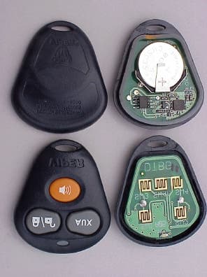
Click to zoom
Application Details
- Equipment Class
- DSC - Part 15 Security/Remote Control Transmitter
- Date of Grant
- Oct 24, 2002
- Application Purpose
- Original Equipment
- Date of Application
- Oct 24, 2002
- Equipment Note
- Viper Transmitter, Model 474V
- Frequency Range
- 433.92000000 - 433.92000000
- Company
- Voxx Electronics Corporation
- Country
- United States
Documents & Files
Document Text
Text extracted from the exhibit documents filed with the FCC. Open a document above to read the original.
Users Manual
Single-Button ConfigurationA remote that has been programmed to a single-but-ton configuration will control both arm/lock and dis-arm/unlock from the same button. Using the one-but-ton configuration, the transmitter buttons are assignedto the following functions: Lock Icon Button The lock icon button arms/locks and disarms/unlocksthe system. When held for three seconds, Panicmode is activated Unlock Icon Button The unlock icon button operates Channel 2 and silentarms/locks and disarms/unlocks. Unlock and Lock Icon Buttons When pressed together, the lock and unlock iconbuttons operate channel 3. Standard ConfigurationA remote that has been programmed to an standardconfiguration will use separate buttons for arm anddisarm similar to a factory keyless entry. Using theexpanded configuration, the transmitter buttons areassigned to the following functions: Lock Icon Button The lock icon button arms and locks the system. Unlock Icon Button The unlock icon button disarms and unlocks the system. AUX Icon Buttons The AUX icon button operates channel 2. Siren Icon Button The siren icon button operates Panic only. Unlock and Lock Icon Buttons When pressed together, the lock and unlock iconbuttons operate channel 3. REPLACEMENT TRANSMITTER Model 474V, 4–Button HF, Stealth Code Remote 210HV All 650XV All 850XV All 350HV All SYSTEM Date Code MADE IN TAIWAN © 2002 Directed Electronics, Inc. Vista CA 92083 All rights reserved. 10/02 P/N 474V REPLACEMENT TRANSMITTERModel 474V, 4 Button HF, Stealth Code Remote 1. Door. Open a door (except 210HV). 2. Key. Turn the key to the ON position. 3. Choose. Within 5 seconds press and release the Valet/Program button the number of times corre-sponding to the desired channel listed below.Once you have selected the channel, press theValet/Program button once more and hold it. TheLED will flash the same number of times as thechannel selected and the siren (except 210HV) will chirp to confirm the selected channel. Do NOTrelease the button. 4. Transmit. While holding the Valet/program button, press the button from the transmitter youwish to assign to that channel. The unit will chirp(except 210HV) to confirm that the transmitter has been taught to the receiver 5. Release. Once the code is learned you can release the Valet/Program button and remove the key. The following Learn Routine can be used to programthis replacement transmitter to the system. In order to enter the Learn Routine, the system’s Valet/Programswitch must be plugged into the BLUE port. Channel Number Function 7 Auto-learn Standard Configuration/Expanded (350HV) 8 Auto-learn Single-Button Configuration 9 Delete All Transmitters FCC/ID NoticeThis device complies with Part 15 of FCC rules.Operation is subject to the following conditions: (1) Thisdevice may not cause harmful interference, and (2) Thisdevice must accept any interference received, includinginterference that may cause undesired operation.CAUTION! Changes or modifications not expressly approved by the party responsible for compli-ance could void the user's authority to oper-ate this device. 350HV All REPLACEMENT TRANSMITTER Model 473V, 3–Button HF, Stealth Code Remote SYSTEM Date Code MADE IN TAIWAN © 2002 Directed Electronics, Inc. Vista CA 92083 All rights reserved. 10/02 P/N 473V Single-Button ConfigurationA remote that has been programmed to a single-but-ton configuration will control both arm/lock and dis-arm/unlock from the same button. Using the one-but-ton configuration, the transmitter buttons are assignedto the following functions: Lock/Unlock Icon Button The lock/unlock icon button arms/locks and dis-arms/unlocks the system. AUX Icon Button The AUX icon button operates Channel 2 and silentarm/lock and disarm/unlock. Siren Icon Button The siren icon button operates Panic only. Lock/Unlock and AUX Icon Buttons When pressed simutaneously, the lock/unlock andAUX icon buttons activate Channel 3. FCC/ID NoticeThis device complies with Part 15 of FCC rules.Operation is subject to the following conditions: (1) Thisdevice may not cause harmful interference, and (2) Thisdevice must accept any interference received, includinginterference that may cause undesired operation.CAUTION! Changes or modifications not expressly approved by the party responsible for compli-ance could void the user's authority to oper-ate this device. REPLACEMENT TRANSMITTERModel 473V, 3 Button HF, Stealth Code Remote 1. Door. Open a door. 2. Key. Turn the key to the ON position. 3. Choose. Within 5 seconds press and release the Valet/Program button the number of times corre-sponding to the desired channel listed below.Once you have selected the channel, press theValet/Program button once more and hold it. TheLED will flash the same number of times as thechannel selected and the siren will chirp to confirm the selected channel. Do NOT release the button. 4. Transmit. While holding the Valet/program button, press the button from the transmitter youwish to assign to that channel. The unit will chirpto confirm that the transmitter has been taught tothe receiver 5. Release. Once the code is learned you can release the Valet/Program button and remove the key. The following Learn Routine can be used to programthis replacement transmitter to the system. In order to enter the Learn Routine, the system’s Valet/Programswitch must be plugged into the BLUE port. Channel Number Function 8 Auto-learn Single-Button Configuration 9 Delete All Transmitters
Block Diagram
1234 A B C D 4321 D C B A 474V / 473V A Title: Size:Number: Revision: Date Code: File: Sheet of Drwn By X:\DRAWINGS\CURRENT\Security\TX\DTBG.DDB - Documents\474V block.SCH 11 A Directed Electronics Inc. One Viper Way Vista, CA 92083 Phone: 760-598-6200Fax: 760-598-6400 DTBG Appd By Chkd By Date Date Date 433.92 MHz Green LED BAT+(Clip) BAT-(PCB) 3V Battery T1 SW2 PCB SW1 PCB SW3 PCB SW4 PCB T3 EncoderRF OscillatorPCB Antenna Minas Minassian 10/14/02
External Photos
TOP OF 3 & 4 BUTTON RUBBER KEYPAD BOTTOM OF 3 & 4 BUTTON RUBBER KEYPAD
Internal Photos
BACK OF 474V PCB FRONT OF 474 PCB
Test Report
TÜV AMERICA, INC. 10040 Mesa Rim Road San Diego, CA 92121-2912 Phone 858 546 3999 FAX 858 546 0364 Report No. SC205234-03 Page 1 of 16 Rev.No 1.0 MEASUREMENT AND TECHNICAL REPORT DIRECTED ELECTRONICS INCORPORATED 2560 Progress Street Vista, CA 92083 DATE: 22 October 2002 This Report Concerns: Original Grant: X Class II Change: Equipment Type: Viper Transmitter, Model 474V Deferred grant requested per 47 CFR 0.457(d)(1)(ii)? Yes: Defer until: No: X Company Name agrees to notify the Commission by: N/A of the intended date of announcement of the product so that the grant can be issued on that date. Transition Rules Request per 15.37? Yes: No: X* (*) FCC Part 15, Paragraph(s) 15.231(a), 15.231(b), 15.231(c) Report Prepared by: TÜV AMERICA, INC 10040 Mesa Rim Road San Diego, CA 92121-2912 Phone: 858 546 3999 Fax: 858 546 0364 TÜV AMERICA, INC. 10040 Mesa Rim Road San Diego, CA 92121-2912 Phone 858 546 3999 FAX 858 546 0364 Report No. SC205234-03 Page 2 of 16 Rev.No 1.0 TABLE OF CONTENTS Pages 1.0 GENERAL INFORMATION 3 - 6 1.1 Product Discription 3 - 5 1.2 Related Submittal Grant 6 1.3 Tested System Details 6 1.4 Test Methodology 6 1.5 Test Facility 6 1.6 Part 2 Requirements 6 2.0 SYSTEM TEST CONFIGURATION 7 2.1 Justification 7 2.2 EUT Exercise Software 7 2.3 Special Accessories 7 2.4 Equipment Modifications 7 2.5 Configuration of Test System 7 3.0 DEACTIVATION EQUIPMENT/DATA 8 - 15 RADIATED SPURIOUS EMISSIONS EQUIPMENT/DATA 3.1 Field Strength Calculation EMISSIONS BANDWIDTH EQUIPMENT/DATA DUTY CYCLE MEASUREMENTS EQUIPMENT/DATA 4.0 ATTESTATION STATEMENT 16 TÜV AMERICA, INC. 10040 Mesa Rim Road San Diego, CA 92121-2912 Phone 858 546 3999 FAX 858 546 0364 Report No. SC205234-03 Page 3 of 16 Rev.No 1.0 1.0 GENERAL INFORMATION 1.1 Product Description General Equipment Description -- NOTE: This information will be input into your test report as shown below. EUT Description: Keyfob transmitter EUT Name: Viper Transmitter Model No.: 474V Serial No.: -- Product Options: -- Configurations to be tested: -- Power Requirements Regulations require testing to be performed at typical power ratings in the countries of intended use. (i.e., European power is typically 230 VAC 50 Hz or 400 VAC 50 Hz, single and three phase, respectively) Voltage: 3V (CR2032 lithium Battery) (If battery powered, make sure battery life is sufficient to complete testing.) # of Phases: -- Current (Amps/phase(max)): -- Current (Amps/phase(nominal)): -- Other: -- Other Special Requirements -- Typical Installation and/or Operating Environment (ie. Hospital, Small Business, Industrial/Factory, etc.) Automotive EUT Power Cable Permanent OR Removable Length (in meters): -- Shielded OR Unshielded n Not Applicable TÜV AMERICA, INC. 10040 Mesa Rim Road San Diego, CA 92121-2912 Phone 858 546 3999 FAX 858 546 0364 Report No. SC205234-03 Page 4 of 16 Rev.No 1.0 EUT Interface Ports and Cables Interface Shielding Type Type Termination Connector Type Port Termination EXAMPLE: RS232 o n 2 n o Foil over braid Coaxial Metallized 9- pin D-Sub Characteristic Impedance 6 n o -- EUT Software. Revision Level: -- Description: -- EUT Operating Modes to be Tested -- list the operating modes to be used during test. It is recommended the equipment be tested while operating in a typical operation mode. FCC testing of personal computers and/or peripherals requires that a simple program generate a complete line of upper case H’s. Provide a general description of all software, firmware, and PLD algorithms used in the equipment. List all code modules as described above, with the revision level used during testing. Consult with your TÜV Product Service Representative if additional assistance is required. 1. Continuous transmission with typical modulation. EUT System Components -- List and describe all components which are part of the EUT. For FCC testing a minimum configuration is required. (ie. Mouse, Printer, Monitor, External Disk Drive, Motherboard, etc.) Description Model # Serial # FCC ID # -- Support Equipment -- List and describe all support equipment which is not part of the EUT. (i.e. peripherals, simulators, etc) Description Model # Serial # FCC ID # -- TÜV AMERICA, INC. 10040 Mesa Rim Road San Diego, CA 92121-2912 Phone 858 546 3999 FAX 858 546 0364 Report No. SC205234-03 Page 5 of 16 Rev.No 1.0 Oscillator Frequencies Frequency Derived Frequency Component # / Location Description of Use 433.92 MHz -- -- RF Carrier frequency Power Supply Manufacturer Model # Serial # Type -- Switched-mode: (Frequency) Linear Other: Power Line Filters Manufacturer Model # Location in EUT -- Critical EMI Components (Capacitors, ferrites, etc.) Description Manufacturer Part # or Value Qty Component # / Location -- EMC Critical Detail -- Describe other EMC Design details used to reduce high frequency noise. -- TÜV AMERICA, INC. 10040 Mesa Rim Road San Diego, CA 92121-2912 Phone 858 546 3999 FAX 858 546 0364 Report No. SC205234-03 Page 6 of 16 Rev.No 1.0 1.2 Related Submittal Grant None 1.3 Tested System Details The FCC ID’s for all equipment, plus descriptions of all cables used in the tested system are: None 1.4 Test Methodology Purpose of Test: To demonstrate compliance with the following tests. TEST FCC CFR 47# PASS/FAIL Deactivation 15.231(a) Pass Radiated Spurious Emissions 15.231(b) Pass Emissions Bandwidth 15.231(c) Pass Duty Cycle Measurements ANSI C63.4, Appendix 14, Para. 10 Pass Both Conducted and Radiated testing were performed according to the procedures in FCC/ANSI C63.4 and CSA 108.8-M1983. Radiated testing was performed at an antenna-to-EUT distance of 3 meters (1 - 25 GHz). 1.5 Test Facility The open area test site and conducted measurement data were tested by: TÜV AMERICA, INC 10040 Mesa Rim Road San Diego, CA 92121-2912 Phone: 858 546 3999 Fax: 858 546 0364 The Test Site Data and performance comply with ANSI C63.4 and are registered with the FCC, 7435 Oakland Mills Road, Columbia Maryland 21046. All Measurement Data is acquired according to the content of F…
Text truncated - open the document above for the full version.
Test Setup Photos
Spectrum Analyzer EUT 1 Meter Test Setup for Bandwidth, Deactivation and Duty Cycle Measurements
Contact Information
Applicant
Joseph A. Santavicca(SVP of Engineering)
Test Firm
TUV AmericaJames Owen
Technical Specifications
| # | Rule Parts | Frequency Range | Power Output |
|---|---|---|---|
| 1 | 15.231 | 433.92 MHz - 433.92 MHz | - |
Other Applications from Voxx Electronics Corporation
EZS2403VD
Jan 08, 2026BT/NFC Reader
Equipment Class
JAB - Part 15 Class B Digital DeviceEZS6214T
Dec 02, 2024Transceiver
Equipment Class
DSR - Part 15 Remote Control/Security Device Transceiver
EZS1412VD
Jul 19, 2024KiB Ekey
Equipment Class
DTS - Digital Transmission System
EZS8812
Dec 10, 20228812
Equipment Class
DTS - Digital Transmission System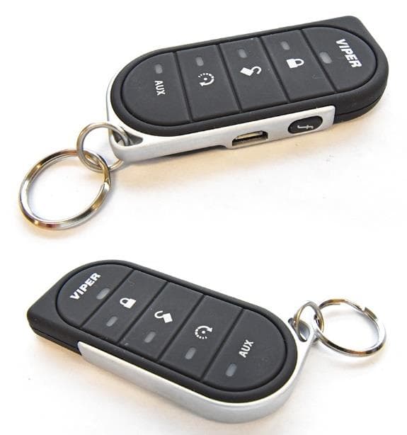
EZSG7857
Mar 22, 2021915MHz Remote Start Handheld Key fob
Equipment Class
DSS - Part 15 Spread Spectrum Transmitter