EZSDEI5472 Way LED
Voxx Electronics Corporation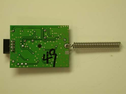
Click to zoom
Application Details
- Equipment Class
- DSC - Part 15 Security/Remote Control Transmitter
- Date of Grant
- Jul 08, 2004
- Application Purpose
- Original Equipment
- Date of Application
- May 16, 2004
- Equipment Note
- 2 Way LED
- Frequency Range
- 433.92000000 - 433.92000000
- Company
- Voxx Electronics Corporation
- Country
- United States
Documents & Files
Document Text
Text extracted from the exhibit documents filed with the FCC. Open a document above to read the original.
Users Manual
© 2004 Directed Electronics, Inc. Vista, CA N567V 05-04 NOTE:This product is intended for installation by a professional installer only! Any attempt to install this product by any person other than a trained professional may result in severe damage to a vehicle’s electrical system and components. MMooddeell 777711 XXVV IInnssttaallllaattiioonn GGuuiiddee ® 22 © 2004 Directed Electronics, Inc. Vista, CA Bitwriter™, Code Hopping™, Doubleguard®, ESP™, FailSafe®, Ghost Switch™, Learn Routine™, Nite-Lite®, Nuisance Prevention Circuitry®, NPC®, Revenger®, Silent Mode™, Soft Chirp®, Stinger®, Valet®, Vehicle Recovery System®, VRS®, and Warn Away® are all Trademarks or Registered Trademarks of Directed Electronics, Inc. NNeeww SSooffttwwaarree CCoommppaattiibbiilliittyy ffoorr 110033TT KKeeyyppaadd This unit now has software that allows arming with entry delay when used in conjunction with the optional 110033TT Keypad. Refer to the 103T Owner’s Guide for details. The Bitwriter ® (p/n 998T) requires chip version 1.4 or newer to program this unit. © 2004 Directed Electronics, Inc. Vista, CA 33 ttaabbllee ooff ccoonntteennttss wwhhaatt iiss iinncclluuddeedd.. .. .. .. .. .. .. .. .. .. .. .. .. .. .. .. .. .. .. .. .. .. .. .. .. .. .. .. 44 wwaarrnniinngg!! ssaaffeettyy ffiirrsstt.. .. .. .. .. .. .. .. .. .. .. .. .. .. .. .. .. .. .. .. .. .. .. .. .. 44 iinnssttaallllaattiioonn ppooiinnttss ttoo rreemmeemmbbeerr.. .. .. .. .. .. .. .. .. .. .. .. .. .. .. .. .. 55 before beginning the installation . . . . . . . . . . . . . 5 after the installation. . . . . . . . . . . . . . . . . . . . . . 5 ddeecciiddiinngg oonn ccoommppoonneenntt llooccaattiioonnss.. .. .. .. .. .. .. .. .. .. .. .. .. .. .. .. 66 locations for the siren . . . . . . . . . . . . . . . . . . . . . 6 locations for the control module . . . . . . . . . . . . . . 6 locations for stinger doubleguard shock sensor . . . . 7 locations for valet/program switch . . . . . . . . . . . . 8 locations for the status LED . . . . . . . . . . . . . . . . . 8 locations for the optional starter kill relay . . . . . . . 9 locations for the relay satellite. . . . . . . . . . . . . . . 9 ffiinnddiinngg tthhee wwiirreess yyoouu nneeeedd.. .. .. .. .. .. .. .. .. .. .. .. .. .. .. .. .. .. .. .. 99 obtaining constant 12V . . . . . . . . . . . . . . . . . . . . 9 finding the 12V switched ignition wire. . . . . . . . . 10 finding the starter wire . . . . . . . . . . . . . . . . . . . 10 finding the accessory wire . . . . . . . . . . . . . . . . . 11 finding the tachometer wire . . . . . . . . . . . . . . . . 11 finding the wait-to-start bulb wire for diesels . . . 11 finding a (+) parking light wire. . . . . . . . . . . . . . 12 finding the door pin switch circuit . . . . . . . . . . . 12 mmaakkiinngg yyoouurr wwiirriinngg ccoonnnneeccttiioonnss.. .. .. .. .. .. .. .. .. .. .. .. .. .. .. .. 1133 pprriimmaarryy hhaarrnneessss ((HH11)),, 1122--ppiinn ccoonnnneeccttoorr.. .. .. .. .. .. .. .. .. .. .. 1144 sseeccoonnddaarryy hhaarrnneessss ((HH22)),, 66--ppiinn ccoonnnneeccttoorr.. .. .. .. .. .. .. .. .. .. 1144 ddoooorr lloocckk hhaarrnneessss,, 33--ppiinn ccoonnnneeccttoorr.. .. .. .. .. .. .. .. .. .. .. .. .. .. 1155 rreemmoottee ssttaarrtt pprriimmaarryy hhaarrnneessss,, 77--ppiinn ccoonnnneeccttoorr.. .. .. .. .. .. 1155 hheeaavvyy ggaauuggee iinnlliinnee ccoonnnneeccttoorr kkeeyy sswwiittcchh iinntteerrffaaccee.. .. .. 1166 rreemmoottee ssttaarrtt sseeccoonnddaarryy hhaarrnneessss ((HH33)),,55--ppiinn ccoonnnneeccttoorr.. 1166 pprriimmaarryy hhaarrnneessss ((HH11)) wwiirree ccoonnnneeccttiioonn gguuiiddee.. .. .. .. .. .. .. .. 1177 sseeccoonnddaarryy hhaarrnneessss ((HH22)) wwiirree ccoonnnneeccttiioonn gguuiiddee.. .. .. .. .. .. 2211 rreellaayy ssaatteelllliittee iiggnniittiioonn sswwiittcchh iinntteerrffaaccee wwiirree ccoonnnneeccttiioonn gguuiiddee.. .. .. .. .. .. .. .. .. .. .. .. .. .. .. .. .. .. .. .. .. .. .. .. .. .. .. .. .. .. .. .. .. .. 2233 heavy gauge wires . . . . . . . . . . . . . . . . . . . . . . 23 ribbon harness . . . . . . . . . . . . . . . . . . . . . . . . . 24 auxiliary relay output harness . . . . . . . . . . . . . . . 24 rreemmoottee ssttaarrtt sseeccoonnddaarryy hhaarrnneessss ((HH33)) wwiirree ccoonnnneeccttiioonn gguuiiddee .. .. .. .. .. .. .. .. .. .. .. .. .. .. .. .. .. .. .. .. .. .. .. .. .. .. .. .. .. .. .. .. .. .. .. .. .. .. 2255 nneeuuttrraall ssaaffeettyy sswwiittcchh iinntteerrffaaccee.. .. .. .. .. .. .. .. .. .. .. .. .. .. .. .. .. 2277 testing the neutral safety switch. . . . . . . . . . . . . 27 bbyyppaassssiinngg GGMM vveehhiiccllee aannttii--tthheefftt ssyysstteemmss ((VVAATTSS)).. .. .. .. .. 3300 11999955 aanndd nneewweerr vveehhiiccllee aannttii--tthheefftt ssyysstteemmss .. .. .. .. .. .. .. .. .. ((iimmmmoobbiilliizzeerrss)).. .. .. .. .. .. .. .. .. .. .. .. .. .. .. .. .. .. .. .. .. .. .. .. .. .. .. .. 3311 passlock I and passlock II (PL-1 and PL-2) . . . . . . 31 passkey III (PK-3), transponder-based systems . . . 31 pplluugg--iinn LLEEDD aanndd vvaalleett//pprrooggrraamm sswwiittcchh.. .. .. .. .. .. .. .. .. .. .. .. 3322 pprrooggrraammmmeerr iinntteerrffaaccee,, 33--ppiinn bbllaacckk pplluugg.. .. .. .. .. .. .. .. .. .. .. 3322 sshhoocckk sseennssoorr hhaarrnneessss,, 44--ppiinn ccoonnnneeccttoorr.. .. .. .. .. .. .. .. .. .. .. .. 3333 ttaacchh lleeaarrnniinngg.. .. .. .. .. .. .. .. .. .. .. .. .. .. .. .. .. .. .. .. .. .. .. .. .. .. .. .. .. 3344 pprrooggrraammmmiinngg jjuummppeerrss.. .. .. .. .. .. .. .. .. .. .. .. .. .. .. .. .. .. .. .. .. .. .. 3344 tach threshold on/off . . . . . . . . . . . . . . . . . . . . 35 light flash (+)/(-) . . . . . . . . . . . . . . . . . . . . . . . 35 ttrraannssmmiitttteerr//rreecceeiivveerr lleeaarrnn rroouuttiinnee™™.. .. .. .. .. .. .. .. .. .. .. .. .. .. 3355 ttrraannssmmiitttteerr ccoonnffiigguurraattiioonnss.. .. .. .. .. .. .. .. .. .. .. .. .. .. .. .. .. .. .. .. 3377 standard configuration. . . . . . . . . . . . . . . . . . . . 3…
Text truncated - open the document above for the full version.
Users Manual
Wednesday, May 12, 2004 TUV Product Services 10040 Mesa Rim Road San Diego, CA 92121 RE: FCC ID EZSDEI487 Dear Sir or Madam, This letter is to address the following for the 547T Transceiver: 1. System transmission frequency range 2. Data transmission duty cycle description 3. Manuals 1. This transmitter is a single frequency device. It has a crystal controlled PLL oscillator which generates the RF carrier. The crystal based oscillator can maintain a center frequency of 433.92MHz within a +/-35KHz tolerance. The receiver operated by this transmitter is a single band receiver tuned to 433.92MHz and only capable of receiving this frequency. 2. The 547T is a data transmission device. Its protocol consists of the following worst case condition for duty cycle credit calculation: a) 17 preamble bits: 9 x 300us HI bits and 8 x 300us LO bits = 2.7ms ON time out of 5.1ms total time. b) There’s a 3ms gap between the preamble bits and the data bits. c) 57 data bits of 300us or 600us each, they are random. Worst case of 600us HI bits and 300us LO will be used. So, 29 x 600us and 28 x 300us LO = 17.4ms HI out of 25.8ms total time. c) There’s a 60ms gap between the end of the data bits and the beginning of the next frame. d) Total worst case word = 2.7ms + 17.4ms = 20.1ms ON time out of 93.9ms (5.1ms+3ms+25.8ms+60ms) So for a worst case 100ms frame we have: 20.1ms ON out of 93.9ms + 3.3ms ON out of 6.1ms = 23.4ms out of 100ms = 23.4% ON time OR a -12.62dB FCC duty cycle credit. 3. There are no dedicated manuals for this device. The 547T transceiver is part of several car alarm and remote start systems. Included are the installation and owner’s guides for the system with the most features which is representative of other, less feature rich systems. The installation guide of all systems have a section covering the wiring of the transceiver. There are no user features associated with this device. Once installed in the vehicle by certified car alarm installers (Just connection) no interfacing to the device is necessary. No user or installer settings are available, the device is purely to do RF communication. Please refer to the wiring diagram on page 53 in the installation guide. Sincerely, Minas Minassian RF Engineer MMooddeell 777711XXVV ➤ OOwwnneerr’’ss GGuuiiddee VViippeerr i © 2004 directed electronics, inc. lliimmiitteedd lliiffeettiimmee ccoonnssuummeerr wwaarrrraannttyy Directed Electronics, Inc. ("Directed") promises to the original purchaser to repair or replace with a comparable reconditioned model any Directed unit (hereafter the "unit"), excluding without limitation the siren, the remote transmitters, the associated sensors and accessories, which proves to be defective in workmanship or material under reasonable use during the lifetime of the vehicle provided the following conditions are met: the unit was professionally installed and serviced by an authorized Directed dealer; the unit will be pro- fessionally reinstalled in the vehicle in which it was originally installed by an authorized Directed dealer; and the unit is returned to Directed, shipping prepaid with a legible copy of the bill of sale or other dated proof of purchase bearing the following information: con- sumer's name, telephone number and address; the authorized dealers name, telephone number and address; complete product description, including accessories; the year, make and model of the vehicle; vehicle license number and vehicle identification number. All components other than the unit, including without limitation the siren, the remote trans- mitters and the associated sensors and accessories, carry a one-year warranty from the date of purchase of the same. This warranty is non-transferable and is automatically void if: the original purchaser has not completed the warranty card and mailed it within ten (10) days of the date of purchase to the address listed on the card; the unit's date code or serial num- ber is defaced, missing or altered; the unit has been modified or used in a manner con- trary to its intended purpose; the unit has been damaged by accident, unreasonable use, neglect, improper service, installation or other causes not arising out of defects in materi- als or construction. The warranty does not cover damage to the unit caused by installa- tion or removal of the unit. Directed, in its sole discretion, will determine what consti- tutes excessive damage and may refuse the return of any unit with excessive damage. TO THE MAXIMUM EXTENT ALLOWED BY LAW, ALL WARRANTIES, INCLUD- ING BUT NOT LIMITED TO EXPRESS WARRANTY, IMPLIED WARRANTY, WARRANTY OF MERCHANTABILITY, FITNESS FOR PARTICULAR PURPOSE AND WARRANTY OF NON-INFRINGEMENT OF INTELLECTUAL PROPERTY, ARE EXPRESSLY EXCLUDED; AND DIRECTED NEITHER ASSUMES NOR AUTHORIZES ANY PERSON OR ENTITY TO ASSUME FOR IT ANY DUTY, OBLIGATION OR LIABILITY IN CONNECTION WITH ITS PRODUCTS. DIRECTED DISCLAIMS AND HAS ABSOLUTELY NO LIABILITY FOR ANY AND ALL ACTS OF THIRD PARTIES INCLUDING ITS AUTHORIZED DEAL- ERS OR INSTALLERS. DIRECTED SECURITY SYSTEMS, INCLUDING THIS UNIT, ARE DETERRENTS AGAINST POSSIBLE THEFT. DIRECTED IS NOT OFFERING A GUARANTEE OR INSURANCE AGAINST VANDALISM, DAM- AGE OR THEFT OF THE AUTOMOBILE, ITS PARTS OR CONTENTS; AND HEREBY EXPRESSLY DISCLAIMS ANY LIABILITY WHATSOEVER, INCLUD- ING WITHOUT LIMITATION, LIABILITY FOR THEFT, DAMAGE AND/OR VANDALISM. THIS WARRANTY DOES NOT COVER LABOR COSTS FOR MAINTENANCE, REMOVAL OR REINSTALLATION OF THE UNIT OR ANY ii © 2004 directed electronics, inc. CONSEQUENTIAL DAMAGES OF ANY KIND. IN THE EVENT OF A CLAIM OR A DISPUTE INVOLVING DIRECTED OR ITS SUBSIDIARY, THE PROPER VENUE SHALL BE SAN DIEGO COUNTY IN THE STATE OF CALIFORNIA. CALIFORNIA STATE LAWS AND APPLICABLE FEDERAL LAWS SHALL APPLY AND GOVERN THE DISPUTE. THE MAXIMUM RECOVERY UNDER ANY CLAIM AGAINST DIRECTED SHALL BE STRICTLY LIMITED TO THE AUTHORIZED DIRECTED DEALER'S PURCHASE PRICE OF THE UNIT. DIRECTED SHALL NOT BE RESPONSIBLE FOR ANY DAMAGES WHATSOEV- ER, INCLUDI…
Text truncated - open the document above for the full version.
Block Diagram
DATA OUT S? SW SPDT ANTENNA VOLTAGE REGULATOR 3.3V 5 V FROM VEHICLE MI CROCONTROLLER 5V TX FROM VEHICLE RX TO VEHICLE 433.92MHz LNA MATC HING CIRCUIT MATC H ING CIRCUIT SAW FILTER 433.92MHz MATC HING CIRCUIT MIX CERAMIC FILTER 10.7MHz IF AMP LPF + - DATA SLICER 13.2256 MHz CRYSTAL PLL SYNTHESIZER IF RECEI VER MIXER AND IMAGE R EJ EC T POWER DOWN MATC H ING CIRCUIT PA PLL C ONTROL ASK IN ON 13.56MHz TRANSMITTER CIRCUIT 5V 3.3V
Cover Letter(s)
Thursday, April 15, 2004 Chief, Equipment Approval Services Federal Communications Commission P.O. Box 358315 Pittsburgh, PA 15251-5315 Dear Sir or Madam: We, Directed Electronics Incorporated, hereby authorize TÜV Product Service (10040 Mesa Rim Road, San Diego, CA 92121, Tel. (619) 546-3999) to act as our agent in all matters relating to applications for equipment authorization, including the signing of all documents relating to these matters. I further certify that the applicant nor any party to the application is subject to a denial of Federal benefits, that includes FCC benefits, pursuant to Section 5301 of the Anti-Drug Abuse Act of 1988, 21 U.S.C. Section 862. This authorization expires on 04/15/05. Sincerely, Mark Rutledge Vice President of Engineering Wednesday, May 12, 2004 Chief, Equipment Approval Services Federal Communications Commission P.O. Box 358315 Pittsburgh, PA 15251-5315 Re: Request of Confidentiality Pursuant to Sections 0.457(d)(1)(ii) and 0.459 of the Commission’s Rules, the Applicant hereby requests confidential treatment of information accompanying as outlined below: Schematics and operating description for EZSDEI547. The above materials contain trade secrets and proprietary information not customarily released to the public. The public disclosure of these matters might be harmful to the Applicant and provide unjustified benefits to its competitors. The Applicant understands that pursuant to Rule 0.457(d)(1)(ii), disclosure of this Application and all accompanying documentation will not be made before the date of the Grant for this Application. Sincerely, Mark Rutledge Vice President of Engineering
External Photos
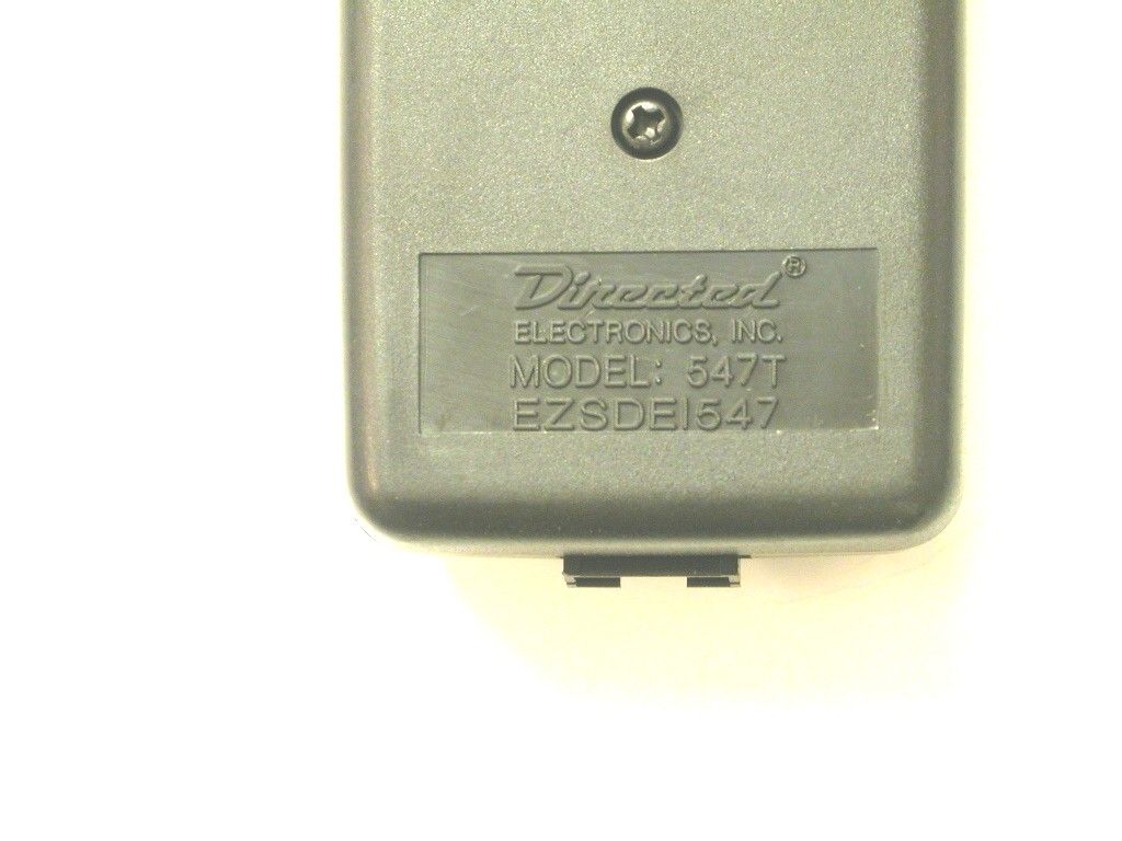
TOP VIEW BOTTOM VIEW BOTTOM VIEW OF PCB TOP AND BOTTOM OF PLASTIC CASE
ID Label/Location Info
FCC ID LABEL FORMAT AND LOCATION Applicant: DIRECTED ELECTRONICS, INC. FCC ID: EZSDEI547 FCC ID: EZSDEI547 This device complies with part 15 of the FCC Rules. Operation is subject to the following two conditions: (1) This device may not cause harmful interference, and (2) this device must accept any interference received, including interference that may cause undesired operation.
ID Label/Location Info
FCC ID LABEL FORMAT AND LOCATION Applicant: DIRECTED ELECTRONICS, INC. FCC ID: EZSDEI547 FCC ID: EZSDEI547 This device complies with part 15 of the FCC Rules. Operation is subject to the following two conditions: (1) This device may not cause harmful interference, and (2) this device must accept any interference received, including interference that may cause undesired operation.
Internal Photos
TOP VIEW OF PCB IN CASE TOP VIEW OF PCB BOTTOM VIEW OF PCB TOP AND BOTTOM OF PLASTIC CASE
Test Report
Report No. SC401730-06A EMC - TEST REPORT UNITED STATES STANDARD FCC PART 15, Paragraph 15.231 Test Report File No. : SC401730-06A Date of Issue: 06 May 2004 Model / Serial No. : 547T / -- Product Type : 2 Way LED Applicant : DIRECTED ELECTRONICS INCORPORATED Manufacturer : DIRECTED ELECTRONICS INCORPORATED License holder : DIRECTED ELECTRONICS INCORPORATED Address : 1 Viper Way : Vista, CA 92081 Test Result : Positive* Negative Test Project Number Reference(s) : SC401730-06A Total pages - Test Report : 22 (*) See General Remarks. NOTE: All test equipment used during testing is calibrated and traceable to NIST. TÜV America reports apply only to the specific sample tested under stated test conditions. It is the manufacturer’s responsibility to assure the continued compliance of production units of this model. TÜV America, Inc. shall have no liability for any deductions, inferences or generalizations drawn by the client or others from TÜV America, Inc. issued reports. This report is the confidential property of the client. As a mutual protection to our clients, the public and ourselves, extracts from the test report shall not be reproduced except in full without our written approval. This report shall not be used by the client to claim product endorsement by NVLAP or any agency of the US government. TÜV America, Inc. and its professional staff hold government and professional organization certifications and are members of AAMI, ACIL, AEA, ANSI, IEEE, NVLAP, and VCCI Page 1 of 7 Rev.No 1.0 TÜV AMERICA INC 10040 Mesa Rim Road San Diego, CA 92121-2912 Phone 858 678 1400 FAX 858 546 0364 Report No. SC401730-06A DIRECTORY Test Report Pages Test Report 1 - 7 Directory 2 Test Regulations 3 General Remarks and Summary 7 Equipment Part 15.231(a) Deactivation 5 Part 15.231(b) Radiated Spurious Emissions 5 Part 15.231(c) Emissions Bandwidth 5 Technical Documentation Test Data Sheets and Test Setup Drawing(s) TD1 Appendices Appendix A - Test Setups (Photographs) A1 Appendix B - Product Information Form(s) B1 Appendix C - Change History C1 Appendix D - Supplemental Information D1 Page 2 of 7 Rev.No 1.0 TÜV AMERICA INC 10040 Mesa Rim Road San Diego, CA 92121-2912 Phone 858 678 1400 FAX 858 546 0364 Report No. SC401730-06A TEST REGULATIONS: The tests were performed according to the following regulations: - EN 50081-1: 1991 - EN 55011: 1998, Amendment A2: 2002 - Group 1 - Group 2 - Class A - Class B - EN 55013: 1990 - EN 55014: 1993 - Household appliances and similar - Portable tools - Semiconductor devices - EN 55022: 1987 - Class A - Class B - EN 55022: 1998, Amendment A2: 2003 - Class A - Class B - VCCI - Class A ITE - Class B ITE - CNS 13438: 1994 - Class A - Class B - FCC Part 15 - 15.231(a) - 15.231(b) - 15.231(c) - AS/NZS 3548: 1995 - Class A - Class B - CISPR 11: 1997 - Group 1 - Group 2 - Class A - Class B - CISPR 22: 1997 - Class A - Class B Page 3 of 7 Rev.No 1.0 TÜV AMERICA INC 10040 Mesa Rim Road San Diego, CA 92121-2912 Phone 858 678 1400 FAX 858 546 0364 Report No. SC401730-06A Environmental Conditions In The Laboratory: Actual Temperature : 23 °C Relative Humidity : 50 % Atmospheric Pressure : 100.0 kPa Power Supply Utilized: Power supply system : 5 V External Symbol Definitions: - Applicable - Not Applicable Page 4 of 7 Rev.No 1.0 TÜV AMERICA INC 10040 Mesa Rim Road San Diego, CA 92121-2912 Phone 858 678 1400 FAX 858 546 0364 Report No. SC401730-06A Test Conditions: Part 15.231(a) Deactivation Part 15.231(b) Radiated Spurious Emissions Part 15.231(c) Emissions Bandwidth The measurements were performed in the following location at the San Diego Testing Facility: - Test not applicable - SR-3, Shielded Room, 12’ x 20’ x 8’, Metal Chamber - Roof (Small Open Area Test Site), 3 meters (Date of listing April 20, 2004. Site Verification Valid for 3 years from listing.) Test Equipment Used: Model No. Prop. No. Description Manufacturer Serial No. Date Cal’ed Equipment List SR-3 1 8566B 823 Spectrum Analyzer Hewlett Packard 2332A02751 09/03 2 CBL6111 460 Bilog Antenna Chase Electronics 1013 NCR* Equipment List Roof 3 3115 453 Double Ridge Antenna EMCO 9412-4364 02/04 4 8566B 744 Spectrum Analyzer Hewlett Packard 2618A02913 01/04 5 AMF-5D- 010180-35-10P 719 Preamplifier Miteq 549460 NCR* 6 FF6549-1 778 High Pass Filter Sage 005 NCR* Remarks: One year calibration cycle for all test equipment and sites. (*) No Calibration Required. No emissions detected between 30 MHz to 1 GHz. See Appendix D for prescans. Page 5 of 7 Rev.No 1.0 TÜV AMERICA INC 10040 Mesa Rim Road San Diego, CA 92121-2912 Phone 858 678 1400 FAX 858 546 0364 Report No. SC401730-06A Equipment Under Test (EUT) Test Operation Mode: The equipment under test was operated under the following conditions during testing: - Standby - Test Program (H - Pattern) - Test Program (Color Bar) - Test Program (Customer Specified) - Practice Operation - Normal Operating Mode - Transmit Configuration of the equipment under test: - See Constructional Data Form in Appendix B - See Product Information Form(s) in Appendix B The following peripheral devices and interface cables were connected during the testing: - Type: - Type: - Type: - Type: - Type: - Type: - Unshielded power cable - Unshielded cables - Shielded cables MPS. No.: - Customer specific cables - - Page 6 of 7 Rev.No 1.0 TÜV AMERICA INC 10040 Mesa Rim Road San Diego, CA 92121-2912 Phone 858 678 1400 FAX 858 546 0364 Report No. SC401730-06A GENERAL REMARKS: NOTE: All photographs are representative of setup for maximum emissions. (*) No emissions detected between 30 MHz to 1 GHz. See Appendix D for prescans. SUMMARY: All tests according to the regulations cited on page 3 were - Performed - Performed with the following exceptions The Equipment Under Test - Fulfills the general approval requirements cited on page 3.* - Does not fulfill the general approval requirem…
Text truncated - open the document above for the full version.
Test Report
Wednesday, May 12, 2004 TUV Product Services 10040 Mesa Rim Road San Diego, CA 92121 RE: FCC ID EZSDEI487 Dear Sir or Madam, This letter is to address the following for the 547T Transceiver: 1. System transmission frequency range 2. Data transmission duty cycle description 3. Manuals 1. This transmitter is a single frequency device. It has a crystal controlled PLL oscillator which generates the RF carrier. The crystal based oscillator can maintain a center frequency of 433.92MHz within a +/-35KHz tolerance. The receiver operated by this transmitter is a single band receiver tuned to 433.92MHz and only capable of receiving this frequency. 2. The 547T is a data transmission device. Its protocol consists of the following worst case condition for duty cycle credit calculation: a) 17 preamble bits: 9 x 300us HI bits and 8 x 300us LO bits = 2.7ms ON time out of 5.1ms total time. b) There’s a 3ms gap between the preamble bits and the data bits. c) 57 data bits of 300us or 600us each, they are random. Worst case of 600us HI bits and 300us LO will be used. So, 29 x 600us and 28 x 300us LO = 17.4ms HI out of 25.8ms total time. c) There’s a 60ms gap between the end of the data bits and the beginning of the next frame. d) Total worst case word = 2.7ms + 17.4ms = 20.1ms ON time out of 93.9ms (5.1ms+3ms+25.8ms+60ms) So for a worst case 100ms frame we have: 20.1ms ON out of 93.9ms + 3.3ms ON out of 6.1ms = 23.4ms out of 100ms = 23.4% ON time OR a -12.62dB FCC duty cycle credit. 3. There are no dedicated manuals for this device. The 547T transceiver is part of several car alarm and remote start systems. Included are the installation and owner’s guides for the system with the most features which is representative of other, less feature rich systems. The installation guide of all systems have a section covering the wiring of the transceiver. There are no user features associated with this device. Once installed in the vehicle by certified car alarm installers (Just connection) no interfacing to the device is necessary. No user or installer settings are available, the device is purely to do RF communication. Please refer to the wiring diagram on page 53 in the installation guide. Sincerely, Minas Minassian RF Engineer
Test Report
Wednesday, May 12, 2004 TUV Product Services 10040 Mesa Rim Road San Diego, CA 92121 RE: FCC ID EZSDEI487 Dear Sir or Madam, This letter is to address the following for the 547T Transceiver: 1. System transmission frequency range 2. Data transmission duty cycle description 3. Manuals 1. This transmitter is a single frequency device. It has a crystal controlled PLL oscillator which generates the RF carrier. The crystal based oscillator can maintain a center frequency of 433.92MHz within a +/-35KHz tolerance. The receiver operated by this transmitter is a single band receiver tuned to 433.92MHz and only capable of receiving this frequency. 2. The 547T is a data transmission device. Its protocol consists of the following worst case condition for duty cycle credit calculation: a) 17 preamble bits: 9 x 300us HI bits and 8 x 300us LO bits = 2.7ms ON time out of 5.1ms total time. b) There’s a 3ms gap between the preamble bits and the data bits. c) 57 data bits of 300us or 600us each, they are random. Worst case of 600us HI bits and 300us LO will be used. So, 29 x 600us and 28 x 300us LO = 17.4ms HI out of 25.8ms total time. c) There’s a 60ms gap between the end of the data bits and the beginning of the next frame. d) Total worst case word = 2.7ms + 17.4ms = 20.1ms ON time out of 93.9ms (5.1ms+3ms+25.8ms+60ms) So for a worst case 100ms frame we have: 20.1ms ON out of 93.9ms + 3.3ms ON out of 6.1ms = 23.4ms out of 100ms = 23.4% ON time OR a -12.62dB FCC duty cycle credit. 3. There are no dedicated manuals for this device. The 547T transceiver is part of several car alarm and remote start systems. Included are the installation and owner’s guides for the system with the most features which is representative of other, less feature rich systems. The installation guide of all systems have a section covering the wiring of the transceiver. There are no user features associated with this device. Once installed in the vehicle by certified car alarm installers (Just connection) no interfacing to the device is necessary. No user or installer settings are available, the device is purely to do RF communication. Please refer to the wiring diagram on page 53 in the installation guide. Sincerely, Minas Minassian RF Engineer
Test Setup Photos
Photograph of Test Setup: Deactivation Emissions Bandwidth Photograph of Test Setup: Radiated Spurious Emissions Photograph of Test Setup: Radiated Spurious Emissions
Contact Information
Applicant
Joseph A. Santavicca(SVP of Engineering)
Test Firm
TUV America Inc.Jim Owen
Technical Specifications
| # | Rule Parts | Frequency Range | Power Output |
|---|---|---|---|
| 1 | 15.231 | 433.92 MHz - 433.92 MHz | - |
Other Applications from Voxx Electronics Corporation
EZS2403VD
Jan 08, 2026BT/NFC Reader
Equipment Class
JAB - Part 15 Class B Digital DeviceEZS6214T
Dec 02, 2024Transceiver
Equipment Class
DSR - Part 15 Remote Control/Security Device Transceiver
EZS1412VD
Jul 19, 2024KiB Ekey
Equipment Class
DTS - Digital Transmission System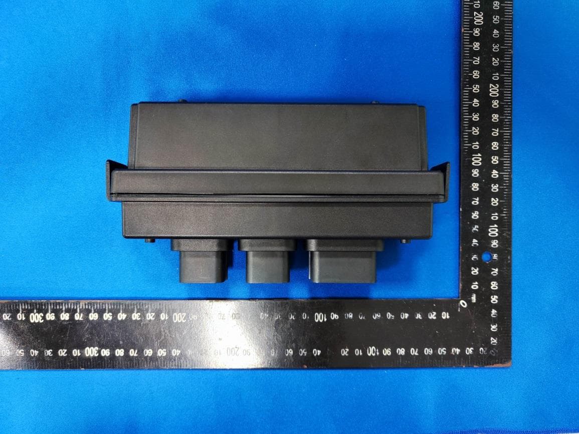
EZS8812
Dec 10, 20228812
Equipment Class
DTS - Digital Transmission System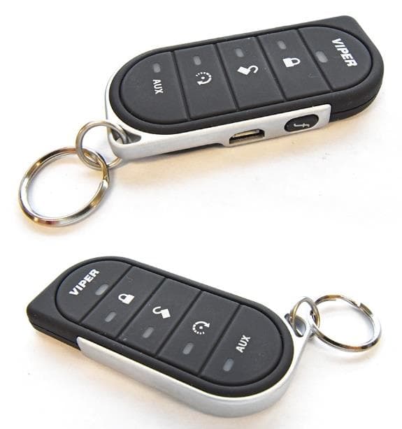
EZSG7857
Mar 22, 2021915MHz Remote Start Handheld Key fob
Equipment Class
DSS - Part 15 Spread Spectrum Transmitter