EZSDEI6816Two way transceiver SST car remote starter (IVU)
Voxx Electronics Corporation
Click to zoom
Application Details
- Equipment Class
- DSS - Part 15 Spread Spectrum Transmitter
- Date of Grant
- Sep 05, 2013
- Application Purpose
- Original Equipment
- Date of Application
- Aug 27, 2013
- Equipment Note
- Two way transceiver SST car remote starter (IVU)
- Frequency Range
- 907.09500000 - 923.83500000
- Company
- Voxx Electronics Corporation
- Country
- United States
Documents & Files
Document Text
Text extracted from the exhibit documents filed with the FCC. Open a document above to read the original.
Users Manual
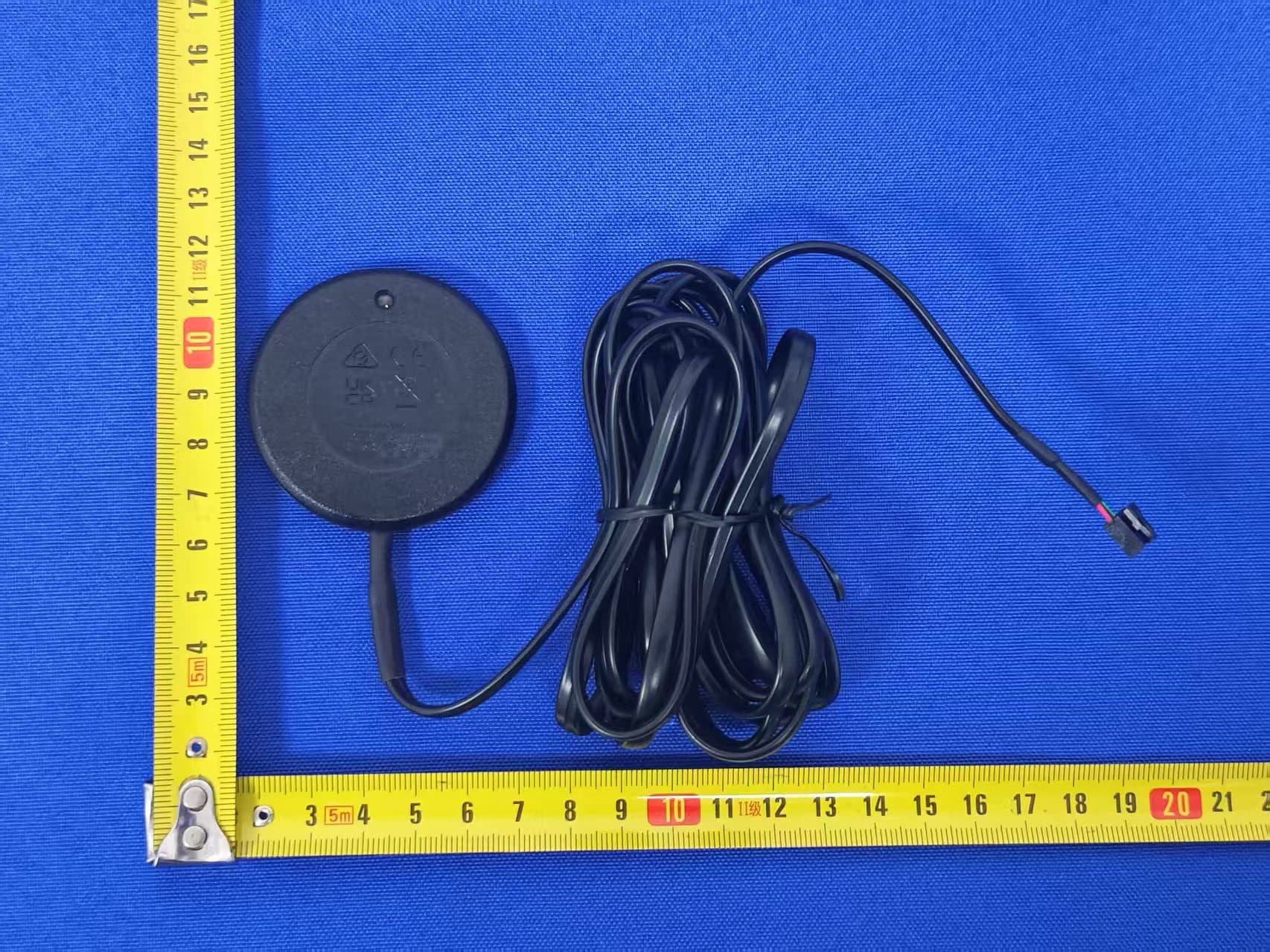
© 2013 Directed, All rights reserved. 1 Product Description The 6816T control center is compatible with the following systems: 3606, 4606, 4706, 4806, 5606, 5706, 5806. It is not compatible with Directed legacy 434MHz ASK or SST systems. Control CenterLEDButton Mounting the Control Center Note Once this replacement control center has been installed, all remote controls must be paired with your system. See Remote Pairing for details and follow the instructions for your remote control type. The control center’s position should be discussed with the vehicle owner prior to installation since the antenna, with built-in status LED and Valet/ Program, must be visible/accessible to the customer. The best position to locate the control center is centered high on the front windshield. It can be mounted vertically or horizontally relative to the windshield. Metallic window tint can also affect range negatively, so this should be a consideration when determining the mounting location. After you determine the best mounting location, follow these steps: Clean the mounting area with a quality glass cleaner or alcohol to remove any dirt or residue. Plug the cable into the control center. Mount the control center with double-sided tape. Route the cable down the window pillar to the control module and plug the cable in the control module. CONTROL CENTER CABLE CONTROL MODULE Remote Pairing Prepare the vehicle system to be Paired with a new remote 1. Open at least one vehicle door. 2. Tu r n the key to the ON position. 3. Within 5 seconds press and release the Control button on the Control Center one time. 4. Within 5 seconds, press and hold the Control button on the Control Center. The status LED begins flashing in single flash sequence and the siren/horn sounds once to confirm the system is ready for remote pairing. Release the button. 5. Locate your remote control model below and follow the instructions. System Pairing will exit if: • The ignition is turned off • The open door is closed • 60 seconds lapses with no actions Note: Make sure the remote to be paired with the system is set for the de- sired Car 1 or Car 2 operation. LCD Remote Control: 1. Press and hold the AUX button for 8 seconds, the remote beeps once, Main Menu is displayed. Release the AUX button. 2. Press the AUX or AUX buttons until Pair is displayed. 3. Press and hold the AUX button until the remote beeps 3 times then re- lease the AUX button. The remote is now ready to pair with the system. 4. Press the AUX button. 5. Wait several seconds for feedback as the remote generates a security encryption and sends it to the Control Center. If pairing is successful the siren/horn sounds and the remote emits several tones. The screen displays if the Pairing is successful or failed with corresponding text. If pairing fails repeat step 4. To exit pairing mode on the remote: • Press and release the A U X button. • Wait 30 seconds without pressing a command button on the remote. Responder LE or Companion Remote Control: 1. Press and hold the AUX button for 8 seconds. The transmit LED will come on solid. Release the AUX button. 2. Press and hold the AUX until the transmit LED flashes 3 times then comes on solid. 3. Press the AUX button. 4. Wait several seconds for feedback as the remote generates a security encryption and sends it to the Control Center. If pairing is successful the siren/horn sounds and the 2-way remote emits several tones (the companion remote does not generate tones). If pairing is not suc- cessful press and release the AUX button once and then repeat steps 2 and 3. To exit pairing mode on the remote: • Press and release the AUX button once, then press and hold until the transmit LED shuts off. • Wait 30 seconds without pressing a command button on the remote control. 6816T Replacement Control Center © 2013 Directed, All rights reserved. 2 GOVERNMENT REGULATIONS This device complies with Part 15 of FCC rules. Operation is subject to the following two conditions: (1) This device may not cause harmful interference, and (2) This device must accept any interference received, including interference that may cause undesirable operation. This equipment has been tested and found to comply with the limits for a class B digital device, pursuant to Part 15 of the FCC Rules. These limits are de- signed to provide reasonable protection against harmful interference in a residential installation. This equipment generates and can radiate radio frequency energy and, if not installed and used in accordance with the instruction manual, may cause harmful interference to radio communications. However, there is no guarantee that interference will not occur in a particular installation. If this equipment does cause harmful interference to radio or television, which can be determined by turning the equipment OFF and ON, the user is encouraged to try to correct the interference by one or more of the following measures: • Reorient or relocate the receiving antenna. • Increase the separation between the equipment and receiver. • Connect the equipment into an outlet on a circuit different from that to which the receiver is connected. • Consult the dealer or an experienced radio / TV technician for help. To satisfy FCC RF exposure compliance requirements, the device and its antenna must maintain a separation distance of 20 cm or more from the person’s body, except for the hand and wrists, to satisfy RF exposure compliance. This device complies with Industry Canada licence-exempt RSS standard(s). Operation is subject to the following two conditions: (1) this device may not cause interference, and (2) this device must accept any interference, including interference that may cause undesired operation of the device. Le présent appareil est conforme aux CNR d’Industrie Canada applicables aux appareils radio exempts de licence. L’exploitation est autorisée aux deux conditions suivantes : (1) l’appareil ne doit pas produire de brouillage, et (2) l’utilisateur de l’a…
Text truncated - open the document above for the full version.
Users Manual
© 2013 Directed, All rights reserved. 1 Product Description The TW-150 control center is compatible with the following systems: AS- 2481TWS, AS-2482TWS, AS-6880TWS, CS-2481TWS, OB-3485, PD485, PS-4481TWS and PS-7880TWS. It is not compatible with Directed legacy 434MHz ASK or SST systems. Mounting the Control Center Note Once this replacement control center has been installed, all remote controls must be paired with your system. See Remote Pairing for details and follow the instructions for your remote control type. The control center’s position should be discussed with the vehicle owner prior to installation since the antenna, with built-in status LED and Valet/ Program, must be visible/accessible to the customer. The best position to locate the control center is centered high on the front windshield. It can be mounted vertically or horizontally relative to the windshield. Metallic window tint can also affect range negatively, so this should be a consideration when determining the mounting location. After you determine the best mounting location, follow these steps: Clean the mounting area with a quality glass cleaner or alcohol to remove any dirt or residue. Plug the cable into the control center. Mount the control center with double-sided tape. Route the cable down the window pillar to the control module and plug the cable in the control module. Remote Pairing ProcedureConfirmations 1. Setting the remote into pairing mode: Press and hold “F” button until the “PAIR MODE” appears on the remote’s LCD screen. “PAIR MODE” text is displayed on the remote’s LCD screen for a period of 30 seconds. 2. Turn the key to IGN ON. 3. Press release and then press and hold the antenna program- ming button until the LED start flashing rapidly The Parking lights will stay ON for 20 seconds. From this point, the installer has 20seconds to complete steps 4-5. 4. Turn the key from IGN ON to IGN OFF and then OFF. The parking light should turn OFF. 5. Press and release lock button.The remote’s LCD screen will dis- play “PASSED “and the parking lights will start flashing to confirm successful learning of the remote. FAILED PAIRING: The remote’s LCD screen will display “FAILED”. First verify if the antenna is still flashing rapidly, if yes, simply redo step4. Other- wise, repeat the whole process from STEP1. 6. Press “F” button once OR leave the remote inactive for 30 seconds. Note1: To learn the remote to a second car that has the same system, in STEP4, press the TRUNK button instead of the LOCK button. Note2: “F” can be AUX or Orbit on the remote TW-150 Replacement Control Center © 2013 Directed, All rights reserved. 2 GOVERNMENT REGULATIONS This device complies with Part 15 of FCC rules. Operation is subject to the following two conditions: (1) This device may not cause harmful interference, and (2) This device must accept any interference received, including interference that may cause undesirable operation. This equipment has been tested and found to comply with the limits for a class B digital device, pursuant to Part 15 of the FCC Rules. These limits are de- signed to provide reasonable protection against harmful interference in a residential installation. This equipment generates and can radiate radio frequency energy and, if not installed and used in accordance with the instruction manual, may cause harmful interference to radio communications. However, there is no guarantee that interference will not occur in a particular installation. If this equipment does cause harmful interference to radio or television, which can be determined by turning the equipment OFF and ON, the user is encouraged to try to correct the interference by one or more of the following measures: • Reorient or relocate the receiving antenna. • Increase the separation between the equipment and receiver. • Connect the equipment into an outlet on a circuit different from that to which the receiver is connected. • Consult the dealer or an experienced radio / TV technician for help. To satisfy FCC RF exposure compliance requirements, the device and its antenna must maintain a separation distance of 20 cm or more from the person’s body, except for the hand and wrists, to satisfy RF exposure compliance. This device complies with Industry Canada licence-exempt RSS standard(s). Operation is subject to the following two conditions: (1) this device may not cause interference, and (2) this device must accept any interference, including interference that may cause undesired operation of the device. Le présent appareil est conforme aux CNR d’Industrie Canada applicables aux appareils radio exempts de licence. L’exploitation est autorisée aux deux conditions suivantes : (1) l’appareil ne doit pas produire de brouillage, et (2) l’utilisateur de l’appareil doit accepter tout brouillage radioélectrique subi, même si le brouillage est susceptible d’en compromettre le fonctionnement. Any changes or modifications not expressly approved by the party responsible for compliance could void the user’s authority to operate the equipment. Les changements ou modifications non approuvés expressément par la partie responsable de la conformité pourrait annuler l’autorité de l’utilisateur à faire fonctionner l’équipement. Warning: Changes or modifications not expressly approved by the party responsible for compliance could void the user’s authority to operate this device. LIMITED ONE YEAR CONSUMER WARRANTY For a period of ONE YEAR from the date of purchase of a Directed Electronics remote start or security product, Directed Electronics. (“DIRECTED”) prom- ises to the original purchaser, to repair or replace with a comparable reconditioned piece, the security or remote start accessory piece (hereinafter the “Part”), which proves to be defective in workmanship or material under normal use, provided the following conditions are met: the Part was purchased from an authorized DIRECTED dealer; and the Part is returned to DIRECTED, postage prepaid, along with a clear, leg…
Text truncated - open the document above for the full version.
Cover Letter(s)
May 7, 2013 Nemko Canada Inc 303 River Road Ottawa, Ontario, Canada K1V 1H2 Attn: Director of Certification IC: 1513A-6816 FCC ID: EZSDEI6816 Models: 6816T, TW150 Family letter This letter explain that Directed are using different models (Viper/ Clifford Model 6816T and Autostart Model TW150 ) on this product. All this models uses the same (PCB, HW/RF), the only change is that each model use different data to communicated with the brain system in the car and that the cases are cosmetically different. All the RF frames in the air are the same with same duty cycle and RF parameters. Sincerely, Minas Minassian Sr. director, hw/rf systems
Cover Letter(s)
May 7, 2013 Nemko Canada Inc 303 River Road Ottawa, Ontario, Canada K1V 1H2 Attn: Director of Certification FCC ID: EZSDEI6816 Authority to Act as Agent On our behalf, I appoint Alan Laudani of Nemko USA Inc., 2210 Faraday Ave, STE 150, Carlsbad, CA, USA to act as our agent in the preparation of this application for equipment certification. I certify that submitted documents properly describe the device or system for which equipment certification is sought. I also certify that each unit manufactured, imported or marketed, as defined in Federal Communication Commission’s regulations will have affixed to it a label identical to that submitted for approval with this application. For instances where our authorized agent signs the application for certification on our behalf, I acknowledge that all responsibility for complying with the terms and conditions for certification, as specified by Nemko USA Inc, still resides with Minas Minassian, DEI Headquarters, Inc 1Viper way, Vista CA 92081, USA. This appointment is in effect until May 7, 2014. Sincerely, Minas Minassian Sr. director, hw/rf systems
Cover Letter(s)
May 7, 2013 Nemko Canada Inc 303 River Road Ottawa, Ontario, Canada K1V 1H2 Attn: Director of Certification Re: Request of Confidentiality Pursuant to Sections 0.457(d)(1)(ii) and 0.459 of the Commission’s Rules, the Applicant hereby requests confidential treatment of information accompanying as outlined below: Schematics Block diagram Operational description Parts List All the above for EZSDEI6816 The above materials contain trade secrets and proprietary information not customarily released to the public. The public disclosure of these matters might be harmful to the Applicant and provide unjustified benefits to its competitors. The Applicant understands that pursuant to Rule 0.457(d)(1)(ii), disclosure of this Application and all accompanying documentation will not be made before the date of the Grant for this Application. Sincerely, Minas Minassian Sr. director, hw/rf systems
External Photos
Model 6816T Model TW‐150
RF Exposure Info
May 7, 2013 Chief, Equipment Approval Services Federal Communications Commission P.O. Box 358315 Pittsburgh, PA 15251-5315 RE: FCC ID EZSDEI6816 Dear Sir or Madam: The following is the SAR calculation for the EUT filed under EZSDEI6816 using the system’s maximum RF emissions. The calculation is based on FCC 47CFR Part 2 and OET 65. Per OET 65: Maximum permissible exposure is the Freq. (MHz) ÷ 1500 = MPE/cm² 923.835MHz (highest used freq.) ÷ 1500 = 0.6123mW/cm² The following equations determine the distance from the antenna that the power density is ≤ 0.6123mW/cm². +19.25dBm Transmitter Power (Max) 0dBi Antenna Gain (Max) +19.25dBm + 0dBi = +19.25dBm EIRP +19.25dBm EIRP = 84.14mW EIRP 0.6123mW/cm² = 84.14mW ÷ (4 x π x r²) r = SQR(84.14 ÷ 4 x π x 0.6123) r = 3.31cm We would like to emphasize that this device is a hand held remote control for vehicle security and convenience systems. The typical use is for unlocking/locking door locks, activating a car alarm or remote starting the vehicle. We estimate that the typical user will activate the remote about 20 times for a period of 2 seconds on average in a 24 hour period. Therefore, the exposure risk to the user is further minimized by the very low duty cycle of on time of the device. In addition, the following statement will be added to our installation/operation manual: To satisfy FCC RF exposure compliance requirements, this device should be used in hand-held, hand-operated configurations only. The device and its antenna must maintain a separation distance of 20cm or more from a person’s body, except for the hand and wrists, to satisfy RF exposure compliance. This device is designed to be used in a person’s hands and its operating configurations do not support normal transmissions while it is carried in pockets or holsters next to a person’s body. Sincerely, Minas Minassian Sr. director, hw/rf systems
Test Report
Nemko-CCL, Inc. 1940 West Alexander Street Salt Lake City, UT 84119 801-972-6146 Test Report Certification Test Of: 6816T & TW-150 FCC ID: EZSDEI16816 Test Specification: FCC PART 15, Subpart C Test Report Serial No: 230382-9-2.3 Applicant: DEI Headquarters Inc. 1 Viper Way Vista, CA 92081 Dates of Test: May 29 - June 7, 2013 Report Issue Date: July 11, 2013 Accredited Testing Laboratory By: NVLAP Lab Code 100272-0 Nemko-CCL, Inc. TEST REPORT: 230382-9-2.3 REPORT ISSUE DATE: 07/11/2013 Page 2 of 46 CERTIFICATION OF ENGINEERING REPORT This report has been prepared by Nemko-CCL, Inc. to document compliance of the device described below with the requirements of Federal Communications Commission (FCC) Part 15, Subpart C. This report may be reproduced in full; partial reproduction may only be made with the written consent of the laboratory. The results in this report apply only to the sample tested. - Applicant: DEI Headquarters Inc. - Manufacturer: DEI Headquarters Inc. - Brand Name: DEI Headquarters Inc. - Model Numbers: 6816T & TW-150 - FCC ID Number: EZSDEI16816 On this 11 th day of July 2013, I, individually and for Nemko-CCL, Inc., certify that the statements made in this engineering report are true, complete, and correct to the best of my knowledge, and are made in good faith. Although NVLAP has recognized that the Nemko-CCL, Inc. EMC testing facilities are in good standing, this report must not be used to claim product certification, approval, or endorsement by NVLAP, NIST, or any agency of the federal government. Nemko-CCL, Inc. Tested by: Mark M. Feil EMC Engineer Reviewed by: Thomas C. Jackson General Manager Nemko-CCL, Inc. TEST REPORT: 230382-9-2.3 REPORT ISSUE DATE: 07/11/2013 Page 3 of 46 TABLE OF CONTENTS PAGE SECTION 1.0 CLIENT INFORMATION .................................................................................4 SECTION 2.0 EQUIPMENT UNDER TEST (EUT) ..................................................................5 SECTION 3.0 TEST SPECIFICATION, METHODS & PROCEDURES .............................9 SECTION 4.0 OPERATION OF EUT DURING TESTING ..................................................14 SECTION 5.0 SUMMARY OF TEST RESULTS ...................................................................15 SECTION 6.0 MEASUREMENTS, EXAMINATIONS AND DERIVED RESULTS ..........16 APPENDIX 1 TEST PROCEDURES AND TEST EQUIPMENT ..........................................36 APPENDIX 2 PHOTOGRAPHS ................................................................................................39 APPENDIX 3 AVERAGE FACTOR CALCULATION ..........................................................46 Nemko-CCL, Inc. TEST REPORT: 230382-9-2.3 REPORT ISSUE DATE: 07/11/2013 Page 4 of 46 SECTION 1.0 CLIENT INFORMATION 1.1 Applicant: Company Name: DEI Headquarters Inc. 1 Viper Way Vista, CA 92081 Contact Name: Minas Minassian Title: Sr. Director, HW/RF Systems 1.2 Manufacturer: Company Name: DEI Headquarters Inc. 1 Viper Way Vista, CA 92081 Contact Name: Minas Minassian Title: Sr. Director, HW/RF Systems Nemko-CCL, Inc. TEST REPORT: 230382-9-2.3 REPORT ISSUE DATE: 07/11/2013 Page 5 of 46 SECTION 2.0 EQUIPMENT UNDER TEST (EUT) 2.1 Identification of EUT: Brand Name: DEI Headquarters Inc. Model Numbers: 6816T & TW-150 Dimensions: 6.0 cm x 2.9 cm x 0.7 cm 2.2 Description of EUT: The 6816T was tested as a representative of models 6816T & TW-150. The differences in the models are cosmetic only. The 6816T, only, will be referred to throughout the remainder of this report. The 6816T is a handheld key fob, exercised by push buttons to arm/disarm, lock/unlock, start vehicle systems, etc. A continuous transmit mode was configured by the applicant for RF testing. The device is powered by a 3.7 V battery. The 6816T transceiver operates using 25 channels, spaced 622 KHz apart, in the 902 MHz to 928 MHz frequency band. The 6816T transceiver uses a helical antenna extending from a trace on the PCB. Testing was performed at the upper channel (923.835 MHz), the middle channel (916.395 MHz), and the lower channel (907.095 MHz). See the plots of the channels below. Nemko-CCL, Inc. TEST REPORT: 230382-9-2.3 REPORT ISSUE DATE: 07/11/2013 Page 6 of 46 Nemko-CCL, Inc. TEST REPORT: 230382-9-2.3 REPORT ISSUE DATE: 07/11/2013 Page 7 of 46 This report covers the circuitry of the devices subject to FCC Part 15, Subpart C. The circuitry of the device subject to FCC Part 15, Subpart B has been tested and found to comply. See Nemko-CCL report #230382-9-1.2. Nemko-CCL, Inc. TEST REPORT: 230382-9-2.3 REPORT ISSUE DATE: 07/11/2013 Page 8 of 46 2.3 EUT and Support Equipment: The EUT and support equipment used during the test are listed below: Brand Name Model Number Serial Number FCC ID Number or Compliance Description Name of Interface Ports / Interface Cables BN: DEI Headquarters Inc. MN: 6816T (Note 1) EZSDEI16816 Key fob remote None Note: (1) EUT The support equipment listed above was not modified in order to achieve compliance with this standard. 2.4 Modification Incorporated/Special Accessories on EUT: No modifications were made during testing to comply with the specification. Nemko-CCL, Inc. TEST REPORT: 230382-9-2.3 REPORT ISSUE DATE: 07/11/2013 Page 9 of 46 SECTION 3.0 TEST SPECIFICATION, METHODS & PROCEDURES 3.1 Test Specification: Title: FCC PART 15, Subpart C (47 CFR 15) 15.203 and 15.247 Limits and methods of measurement of radio interference characteristics of radio frequency devices Purpose of Test: The tests were performed to demonstrate initial compliance 3.2 Methods & Procedures: 3.2.1 §15.203 Antenna Requirement An intentional radiator shall be designed to ensure that no antenna other than that furnished by the responsible party shall be used with the device. The use of a permanently attached antenna or of an antenna that uses a unique coupling to the intentional radiator shall be considered sufficient to comply with the provisions of this Section. The manufacturer may design the unit so that a broken antenna can …
Text truncated - open the document above for the full version.
Contact Information
Applicant
Joseph A. Santavicca(SVP of Engineering)
Technical Contact
Test Firm
Nemko-CCL incThomas Jackson
Technical Specifications
| # | Rule Parts | Frequency Range | Power Output |
|---|---|---|---|
| 1 | 15C | 907.095 MHz - 923.835 MHz | 233.00 mW |
Other Applications from Voxx Electronics Corporation
EZS2403VD
Jan 08, 2026BT/NFC Reader
Equipment Class
JAB - Part 15 Class B Digital DeviceEZS6214T
Dec 02, 2024Transceiver
Equipment Class
DSR - Part 15 Remote Control/Security Device Transceiver
EZS1412VD
Jul 19, 2024KiB Ekey
Equipment Class
DTS - Digital Transmission System
EZS8812
Dec 10, 20228812
Equipment Class
DTS - Digital Transmission System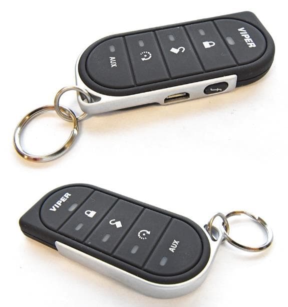
EZSG7857
Mar 22, 2021915MHz Remote Start Handheld Key fob
Equipment Class
DSS - Part 15 Spread Spectrum Transmitter