EZSDEI7541Security/Remote Control Transmitter
Voxx Electronics Corporation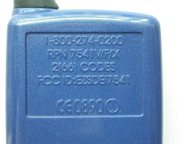
Click to zoom
Application Details
- Equipment Class
- DSC - Part 15 Security/Remote Control Transmitter
- Date of Grant
- Dec 07, 2006
- Application Purpose
- Original Equipment
- Date of Application
- Oct 19, 2006
- Equipment Note
- Security/Remote Control Transmitter
- Frequency Range
- 433.92000000 - 433.92000000
- Company
- Voxx Electronics Corporation
- Country
- United States
Documents & Files
Document Text
Text extracted from the exhibit documents filed with the FCC. Open a document above to read the original.
Users Manual
DRAFT © 2006 Directed Electronics, Vista, CA N5501V 10-06 NOTE: This product is intended for installation by a professional installer only! Any attempt to install this product by any person other than a trained professional may result in severe damage to a vehicle’s electrical system and components. Model 7900 Installation Guide DRAFT DRAFT 2 © 2005 Directed Electronics—all rights reserved Bitwriter®, Code Hopping™, Doubleguard®, ESP™, FailSafe®, Ghost Switch™, Learn Routine™, Nite- Lite®, Nuisance Prevention® Circuitry, Revenger®, Silent Mode™, Soft Chirp®, Stinger®, Valet®, Vehicle Recovery System®, VRS®, and Warn Away® are all Trademarks or Registered Trademarks of Directed Electronics. New Software Compatibility for 103T Keypad This unit now has software that allows arming with entry delay when used in conjunction with the optional 103T Keypad. Refer to the 103T Owner’s Guide for details. The Bitwriter ® (p/n 998T) requires chip version 2.2 or newer to program this unit. DRAFT DRAFT © 2005 Directed Electronics—all rights reserved 3 table of contents what is included . . . . . . . . . . . . . . . . . . . . . . . . . . .4 warning! safety first . . . . . . . . . . . . . . . . . . . . . . . .4 installation points to remember . . . . . . . . . . . . . . .5 before beginning the installation . . . . . . . . . . . . . 5 after the installation . . . . . . . . . . . . . . . . . . . . . 5 deciding on component locations . . . . . . . . . . . . . .6 locations for the siren . . . . . . . . . . . . . . . . . . . . 6 locations for the control module . . . . . . . . . . . . . 6 locations for stinger doubleguard shock sensor . . . 7 mounting the antenna . . . . . . . . . . . . . . . . . . . . 7 locations for valet/program switch . . . . . . . . . . . . 8 locations for the status LED . . . . . . . . . . . . . . . . 8 finding the wires you need . . . . . . . . . . . . . . . . . . .9 locations for the optional starter kill relay . . . . . . 9 locations for the relay satellite . . . . . . . . . . . . . . 9 obtaining constant 12V . . . . . . . . . . . . . . . . . . . 9 finding the 12V switched ignition wire . . . . . . . . 10 finding the starter wire . . . . . . . . . . . . . . . . . . 10 finding the tachometer wire . . . . . . . . . . . . . . . 11 finding the accessory wire . . . . . . . . . . . . . . . . 11 finding the wait-to-start bulb wire for diesels . . . 11 finding a (+) parking light wire . . . . . . . . . . . . . 12 finding the door pin switch circuit . . . . . . . . . . . 12 making your wiring connections . . . . . . . . . . . . . .13 primary harness (H1), 12-pin connector . . . . . . . .14 auxiliary harness (H2), 6-pin connector . . . . . . . . .14 door lock harness, 3-pin connector . . . . . . . . . . . .15 remote start ribbon harness, wiring diagram . . . . . 15 heavy gauge inline connector key switch interface . 16 remote start harness (H3), 5-pin connector . . . . . . 16 horn, channel 6 (H4), 2-pin connector . . . . . . . . .16 relay satellite wire connection guide . . . . . . . . . . .23 remote start secondary harness (H3) wire . . . . . . . . . connection guide . . . . . . . . . . . . . . . . . . . . . . . . .24 horn, channel 6 harness (H4) wire connection guide 26 neutral safety switch interface . . . . . . . . . . . . . . .26 testing the neutral safety switch . . . . . . . . . . . . 27 bypassing GM vehicle anti-theft systems (VATS) . . . 29 1995 and newer vehicle anti-theft systems . . . . . . . . (immobilizers) . . . . . . . . . . . . . . . . . . . . . . . . . . .30 passlock I and passlock II (PL-1 and PL-2) . . . . . 30 passkey III (PK-3), transponder-based systems . . 30 plug-in LED and valet/program switch . . . . . . . . . .31 programmer interface, 3-pin black plug . . . . . . . . .31 shock sensor harness, 4-pin connector . . . . . . . . . .32 tach learning . . . . . . . . . . . . . . . . . . . . . . . . . . . .32 programming jumpers . . . . . . . . . . . . . . . . . . . . . .33 tach threshold on/off . . . . . . . . . . . . . . . . . . . . 33 light flash (+)/(-) . . . . . . . . . . . . . . . . . . . . . . 33 transmitter/receiver learn routine™ . . . . . . . . . . . .34 standard configuration . . . . . . . . . . . . . . . . . . . 36 remote control diagram . . . . . . . . . . . . . . . . . . . . .37 standard mode configuration . . . . . . . . . . . . . . . . .38 multi-level security arming . . . . . . . . . . . . . . . . . .39 system features learn routine . . . . . . . . . . . . . . . .40 feature menus . . . . . . . . . . . . . . . . . . . . . . . . . . .42 menu #1 - basic features . . . . . . . . . . . . . . . . . 42 menu #2 - advanced features. . . . . . . . . . . . . . . 43 menu #3 - remote start options . . . . . . . . . . . . . 44 feature descriptions . . . . . . . . . . . . . . . . . . . . . . .45 menu #1 - basic features . . . . . . . . . . . . . . . . . 45 menu #2 - advanced features. . . . . . . . . . . . . . . 46 menu #3 - remote start options . . . . . . . . . . . . . 49 valet mode . . . . . . . . . . . . . . . . . . . . . . . . . . . . . .51 rear defogger control . . . . . . . . . . . . . . . . . . . . . .51 timer mode . . . . . . . . . . . . . . . . . . . . . . . . . . . . .52 table of zones . . . . . . . . . . . . . . . . . . . . . . . . . . .53 shutdown diagnostics . . . . . . . . . . . . . . . . . . . . . .53 to perform shutdown diagnostics . . . . . . . . . . . . 53 long term event history . . . . . . . . . . . . . . . . . . . .54 safety check . . . . . . . . . . . . . . . . . . . . . . . . . . . .54 troubleshooting . . . . . . . . . . . . . . . . . . . . . . . . . .55 alarm troubleshooting . . . . . . . . . . . . . . . . . . . 55 remote start troubleshooting . . . . . . . . . . . . . . . 56 wiring quick reference guide . . . . . . . . . . . . . . . . .58 relay satellite wiring quick reference guide . . . . . .59 DRAFT DRAFT 4 © 2005 Directed Electronics—all rights reserved what is included ■ The control module ■ The plug-in status LED ■ A Responder receiver/antenn…
Text truncated - open the document above for the full version.
Users Manual
DRAFT © 2005 Directed Electronics—all rights reserved 39 and ............... operate............................Channel 5 and and operate .........................rear defogger and ............... operate............................Channel 6 remote control button/animation locations 1 23 4 DRAFT DRAFT 40 © 2005 Directed Electronics—all rights reserved standard mode configuration 1. Arm Button 2. Auxiliary Button 3. Remote Start Button 4. Disarm Button 5. Programming button DRAFT DRAFT © 2005 Directed Electronics—all rights reserved 41 remote control programming The remote control has programmable features that can be changed to fit the users preferences. Programming can be performed anytime using the programming and function buttons to select the feature menus and change feature settings. Function button operations during programming: • Press the or button to scroll and highlight menu and feature items. • Press the button to choose the highlighted item • Press the button to exit programming anytime Enter programming: Press and hold for 3 seconds the round programming button on the rear of the remote control. The program- ming main menu will appear. Use the function buttons as described above to navigate and change the features. Exit Programming: Press the button anytime to save the settings and exit programming, or, if more than 10 seconds lapses between button presses, the remote control will automatically save the settings and exit programming mode. Power off sleep mode: This setting will make the remote control go to sleep. It will not respond to any RF signals or function button presses. 1. Enter programming mode 2. Scroll to highlight the Clock icon 3. Press the button to choose the Clock and access Clock set screen 4. Scroll and highlight a digit or A/P and then press the button to change the digit. 5. Press the button anytime to save the new setting and exit. Wake Up the remote control: To wake up the remote control press and hold the program button for 3 seconds. The display will cycle through all available animations and icons before becoming active. Set the 12 hour Clock: 1. Enter programming mode DRAFT DRAFT 42 © 2005 Directed Electronics—all rights reserved 2. Scroll to highlight the Clock icon 3. Press to choose the Clock and access Clock set screen 4. Scroll and highlight a digit or A/P and press to change the digit. 5. Press anytime to save the new setting and exit. Page mode on/off: When Page is off, the remote control will not receive Pages or output Page Notifications or Alerts. It will only receive Command Reponses. 1. Enter programming mode 2. Scroll to highlight OPERATION 3. Press to choose the operation menu screen 4. Scroll to highlight PAGE and press to choose. 5. Scroll to highlight the desired setting. 6. Press to save and return to the Operation menu or to save the setting and exit. Beeps on/off: When Beep is off, the remote control will only show animations or icons for Page Notifications. Alarm Page Alerts will be eliminated. 1. Enter programming mode 2. Scroll to highlight OPERATION 3. Press the button to choose the operation menu screen 4. Scroll to highlight BEEP and press to choose. 5. Scroll to highlight the desired setting. 6. Press to save and return to the Operation menu or to save the setting and exit. Custom zone ID: Use this menu item to select which sensor or input information will be displayed when a particular zone is triggered. 1. Enter programming mode 2. Scroll to highlight OPERATION 3. Press to choose the operation menu 4. Scroll to highlight ZONE and press to choose the zone menu. 5. Scroll to highlight the desired zone and press to choose. 6. Scroll to highlight the icon to be displayed for that zone and press to choose. 7. Press to save and return to the zone menu or to save the setting and exit. DRAFT DRAFT © 2005 Directed Electronics—all rights reserved 43 Status Icon Descriptions: Each time the remote control plays any animation due to an Alarm Page or Command Response, icons will be displayed to indicate the current system status. Below is a list of icons and the system characteristics they represent. This icon indicates the DOOR is open or has triggered the alarm This icon indicates the TRUNK is open or has triggered the alarm This icon indicates the system status is ARMED or LOCKED This icon indicates the system status is DISARMED or UNLOCKED This icon indicates the BATTERY charge level This icon indicates the REMOTE START is on and the engine is running This icon indicates the GARAGE DOOR is open This icon indicates the GARAGE DOOR is closed This icon indicates the HOOD is open or has triggered the alarm This icon indicates the IGNITION is on or has triggered the alarm This icon indicates the SIREN is active This icon indicates a SENSOR is active or has triggered the alarm This icon indicates an alarm FULL TRIGGER event has occurred This icon indicates an alarm WARN TRIGGER event has occurred This icon indicates a CALL PAGE from a vehicle occupant was received This icon displays the current TIME DRAFT DRAFT 44 © 2005 Directed Electronics—all rights reserved multi-level security arming Multi-Level Security Arming is a feature that allows the user to select which of the system's inputs or sensors will be active and which will be bypassed when the system is armed. (See Table of Zones section of this guide.) Multi-Level Security Arming can only be accessed from a standard configuration transmitter. Pressing the arm button of the standard configuration transmitter again within five seconds of arming the system will activate the Multi-Level Security feature. Each time the arm button is pressed again, a different security level is selected. The different levels of security are selected as follows: ■ Pressing one time: The siren chirps once. The system is armed. ■ Pressing a second time within five seconds: The siren chirps twice followed by a long chirp. Zone Two is now bypassed. ■ Pressing a third time within five seconds: The siren chir…
Text truncated - open the document above for the full version.
Block Diagram
AntennaCoupledCircuitHarmonicDetector HarmonicFilter F/9 LocalOscillatorFrequency Multiplier IntermediateFrequency 47.02444MHz423.22MHz Receiving InterfaceControl Microcontroller (MCU) Bias pattern (3.3V) DEI_HHU(BLOCK DIAGRAM) (PIC18LF6520) UAA3220TS F/0 LI PolymerBattery DC 3.7V 433.220MHz TransmitterControl S/W TX CONT 10.7MHz RX CONT/TR RX PWR CONT HCS 300 ChargerDC4.2V RegulatorDC 3.3V Imagecontrol KeeLoq Device RXD SAW F434Bias pattern Frequency Multiplier F/0 F/0 Amplification 433.920MHz 48.213333MHz HarmonicFilter F/9 LocalOscillator 433.920MHz 144.64MHz F/3 FrequencyMultiplier 3.3V 2 Remote Contol DEI A3 11 Tuesday, October 10, 2006 TitleSize Document Number Rev Date: Sheet of
Cover Letter(s)
Tuesday, October 10, 2006 TÜV America, Inc. 10040 Mesa Rim Road San Diego, CA 92121 Dear Sir or Madam: We, Directed Electronics Incorporated, hereby authorize TÜV Product Service (10040 Mesa Rim Road, San Diego, CA 92121, Tel. (619) 546-3999) to act as our agent in all matters relating to applications for equipment authorization, including the signing of all documents relating to these matters. I further certify that the applicant nor any party to the application is subject to a denial of Federal benefits, that includes FCC benefits, pursuant to Section 5301 of the Anti-Drug Abuse Act of 1988, 21 U.S.C. Section 862. This authorization expires on 10/10/07. Sincerely, Minas Minassian RF Engineering Manager Thursday, October 12, 2006 Chief, Equipment Approval Services Federal Communications Commission P.O. Box 358315 Pittsburgh, PA 15251-5315 Re: Request of Confidentiality Pursuant to Sections 0.457(d)(1)(ii) and 0.459 of the Commission’s Rules, the Applicant hereby requests confidential treatment of information accompanying as outlined below: Schematics and operating description for EZSDEI7541. The above materials contain trade secrets and proprietary information not customarily released to the public. The public disclosure of these matters might be harmful to the Applicant and provide unjustified benefits to its competitors. The Applicant understands that pursuant to Rule 0.457(d)(1)(ii), disclosure of this Application and all accompanying documentation will not be made before the date of the Grant for this Application. Sincerely, Minas Minassian RF Engineering Manager
Test Report
Report No. SC605588-08 Page 1 of 15 Rev.No 1.0 TÜV AMERICA INC 10040 Mesa Rim Road San Diego, CA 92121-2912 Phone 858 678 1400 FAX 858 546 0364 MEASUREMENT AND TECHNICAL REPORT DIRECTED ELECTRONICS INCORPORATED 1 Viper Way Vista, CA 92083 DATE: 16 October 2006 This Report Concerns: Original Grant: X Class II Change: Equipment Type: 7541VPX HHU Deferred grant requested per 47 CFR 0.457(d)(1)(ii)? Yes: Defer until: No: X Company Name agrees to notify the Commission by: N/A of the intended date of announcement of the product so that the grant can be issued on that date. Transition Rules Request per 15.37? Yes: No: X* (*) FCC Part 15, Paragraph(s) 15.231(a), 15.231(b), 15.231(c) Report Prepared by: TÜV AMERICA, INC 10040 Mesa Rim Road San Diego, CA 92121-2912 Phone: 858 678 1400 Fax: 858 546 0364 Report No. SC605588-08 Page 2 of 15 Rev.No 1.0 TÜV AMERICA INC 10040 Mesa Rim Road San Diego, CA 92121-2912 Phone 858 678 1400 FAX 858 546 0364 TABLE OF CONTENTS Pages 1.0 GENERAL INFORMATION 3 - 5 2.0 SYSTEM TEST CONFIGURATION 6 3.0 EQUIPMENT/DATA DEACTIVATION FIELD STRENGTH OF FUNDAMENTAL EMISSION BANDWIDTH 7 - 18 4.0 ATTESTATION STATEMENT 19 Report No. SC605588-08 Page 3 of 15 Rev.No 1.0 TÜV AMERICA INC 10040 Mesa Rim Road San Diego, CA 92121-2912 Phone 858 678 1400 FAX 858 546 0364 1.0 GENERAL INFORMATION 1.1 Product Description Report No. SC605588-08 Page 4 of 15 Rev.No 1.0 TÜV AMERICA INC 10040 Mesa Rim Road San Diego, CA 92121-2912 Phone 858 678 1400 FAX 858 546 0364 1.2 Related Submittal Grant None 1.3 Tested System Details The FCC ID’s for all equipment, plus descriptions of all cables used in the tested system are: None 1.4 Test Methodology Purpose of Test: To demonstrate compliance with the following tests. Test Description Paragraph Number Pass/Fail Deactivation 15.231(a) Pass Field Strength of Fundamental 15.231(b) Pass Emissions Bandwidth 15.231(c) Pass Field Strength of Emissions 15.231(e) N/A Testing was performed according to the procedures in FCC/ANSI C63.4 and CSA 108.8-M1983. 1.5 Test Facility The open area test site and conducted measurement data were tested by: TÜV AMERICA, INC 10040 Mesa Rim Road San Diego, CA 92121-2912 Phone: 858 678 1400 Fax: 858 546 0364 The Test Site Data and performance comply with ANSI C63.4 and are registered with the FCC, 7435 Oakland Mills Road, Columbia Maryland 21046. All Measurement Data is acquired according to the content of FCC Measurement Procedure and ANSI C63.4, unless supplemented with additional requirements as noted in the test report. Report No. SC605588-08 Page 5 of 15 Rev.No 1.0 TÜV AMERICA INC 10040 Mesa Rim Road San Diego, CA 92121-2912 Phone 858 678 1400 FAX 858 546 0364 2.0 SYSTEM TEST CONFIGURATION 2.1 Justification The EUT was initially tested for FCC emissions in the following configuration: See Test Setup Photos Exhibit 2.2 EUT Exercise Software None 2.3 Special Accessories None 2.4 Equipment Modifications None 2.5 Configuration of Test System See Test Setup Photos Exhibit Report No. SC605588-08 Page 6 of 15 Rev.No 1.0 TÜV AMERICA INC 10040 Mesa Rim Road San Diego, CA 92121-2912 Phone 858 678 1400 FAX 858 546 0364 3.0 DEACTIVATION EQUIPMENT/DATA FIELD STRENGTH OF FUNDAMENTAL EQUIPMENT/DATA EMISSION BANDWIDTH EQUIPMENT/DATA FIELD STRENGTH OF EMISSIONS EQUIPMENT/DATA Test Conditions: DEACTIVATION: FCC Part 15.231(a) FIELD STRENGTH OF FUNDAMENTAL: FCC Part 15.231(b) EMISSION BANDWIDTH: FCC Part 15.231(c) FIELD STRENGTH OF EMISSIONS: FCC Part 15.231(e) The following measurements were performed at the San Diego Testing Facility: - Test not applicable - Roof (Small Open Area Test Site) Test Equipment Used: Model No. Prop. No. Description Manufacturer Serial No. Date Cal’ed 3146 6641 Log Periodic Antenna EMCO 106X 07/06 3115 6669 Double Ridge Antenna EMCO 9412-4364 08/06 AMF-5D-010180-35-10P 6786 Preamplifier Miteq 549460 Verified FF6549-1 777 High Pass Filter Sage 004 Verified FF6549-1 777 High Pass Filter Sage 004 Verified AA-19030.00.0 7492 30’ Coaxial Cable United Microwave -- N/A E4440A 7500 Spectrum Analyzer Hewlett Packard MY43362168 01/06 Remarks: One year calibration cycle for all test equipment and sites. Report No. SC605588-08 Page 7 of 15 Rev.No 1.0 TÜV AMERICA INC 10040 Mesa Rim Road San Diego, CA 92121-2912 Phone 858 678 1400 FAX 858 546 0364 FCC Part 15.231(a) – Deactivation Report No. SC605588-08 Page 8 of 15 Rev.No 1.0 TÜV AMERICA INC 10040 Mesa Rim Road San Diego, CA 92121-2912 Phone 858 678 1400 FAX 858 546 0364 FCC Part 15.231(b) - Field Strength of Fundamental Report No. SC605588-08 Page 9 of 15 Rev.No 1.0 TÜV AMERICA INC 10040 Mesa Rim Road San Diego, CA 92121-2912 Phone 858 678 1400 FAX 858 546 0364 Report No. SC605588-08 Page 10 of 15 Rev.No 1.0 TÜV AMERICA INC 10040 Mesa Rim Road San Diego, CA 92121-2912 Phone 858 678 1400 FAX 858 546 0364 FCC Part 15.231(b) - Duty Cycle Report No. SC605588-08 Page 11 of 15 Rev.No 1.0 TÜV AMERICA INC 10040 Mesa Rim Road San Diego, CA 92121-2912 Phone 858 678 1400 FAX 858 546 0364 FCC Part 15.231(b) - Duty Cycle Report No. SC605588-08 Page 12 of 15 Rev.No 1.0 TÜV AMERICA INC 10040 Mesa Rim Road San Diego, CA 92121-2912 Phone 858 678 1400 FAX 858 546 0364 FCC Part 15.231(b) - Duty Cycle Report No. SC605588-08 Page 13 of 15 Rev.No 1.0 TÜV AMERICA INC 10040 Mesa Rim Road San Diego, CA 92121-2912 Phone 858 678 1400 FAX 858 546 0364 FCC Part 15.231(b) - Duty Cycle Report No. SC605588-08 Page 14 of 15 Rev.No 1.0 TÜV AMERICA INC 10040 Mesa Rim Road San Diego, CA 92121-2912 Phone 858 678 1400 FAX 858 546 0364 FCC Part 15.231(c) - Emission Bandwidth Report No. SC605588-08 Page 15 of 15 Rev.No 1.0 TÜV AMERICA INC 10040 Mesa Rim Road San Diego, CA 92121-2912 Phone 858 678 1400 FAX 858 546 0364 4.0 ATTESTATION STATEMENT GENERAL REMARKS: SUMMARY: All tests were performed per CFR 47, Part(s) 15.231(a), 15.231(b), 15.231(c) - Performed The Equipment Under Test - Fulfills the requirements of CFR 47, Part(s) 15.231(a), 15.231(b), 15.231(c) Testing Start Date: 31 May 2006 Testing End Dat…
Text truncated - open the document above for the full version.
Contact Information
Applicant
Joseph A. Santavicca(SVP of Engineering)
Test Firm
TUV America Inc.Jim Owen
Technical Specifications
| # | Rule Parts | Frequency Range | Power Output |
|---|---|---|---|
| 1 | 15.231 | 433.92 MHz - 433.92 MHz | - |
Other Applications from Voxx Electronics Corporation
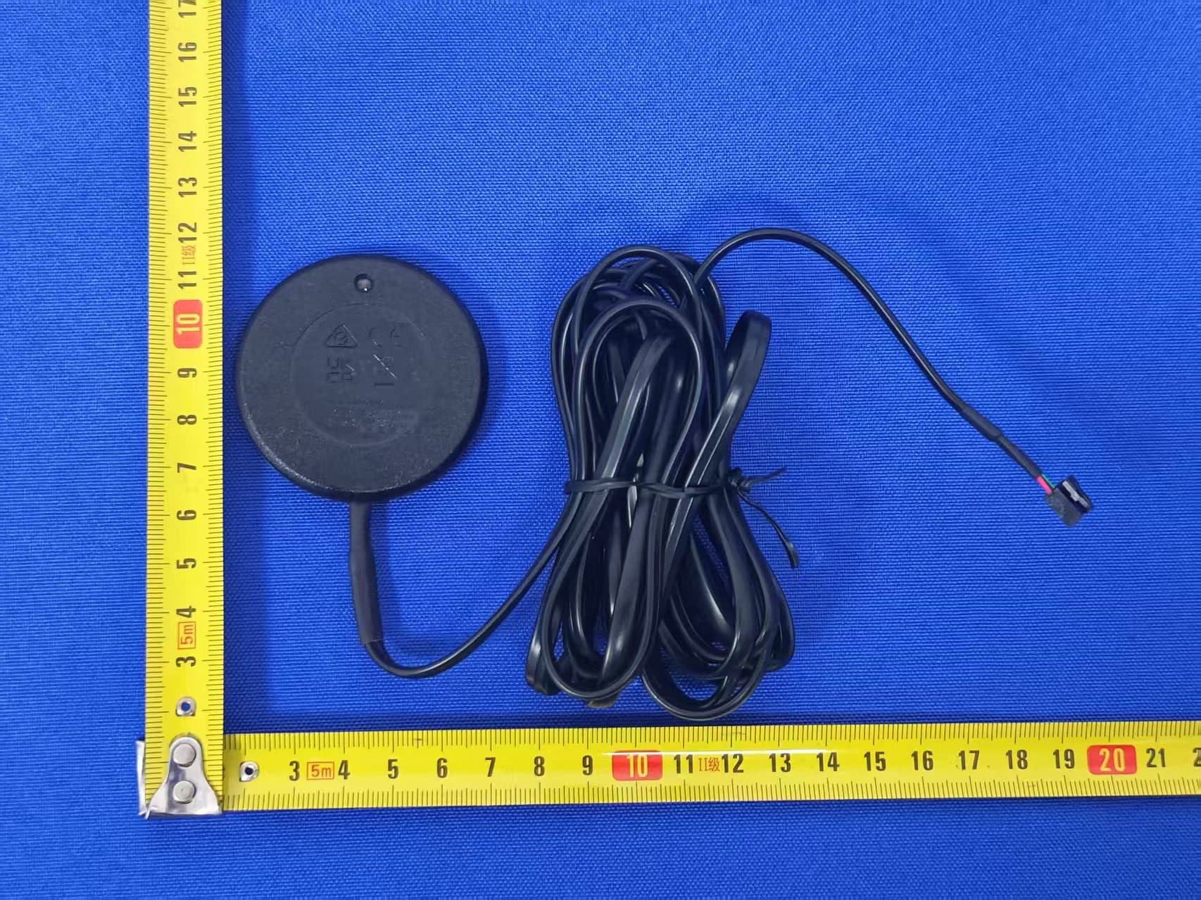
EZS2403VD
Jan 08, 2026BT/NFC Reader
Equipment Class
JAB - Part 15 Class B Digital DeviceEZS6214T
Dec 02, 2024Transceiver
Equipment Class
DSR - Part 15 Remote Control/Security Device Transceiver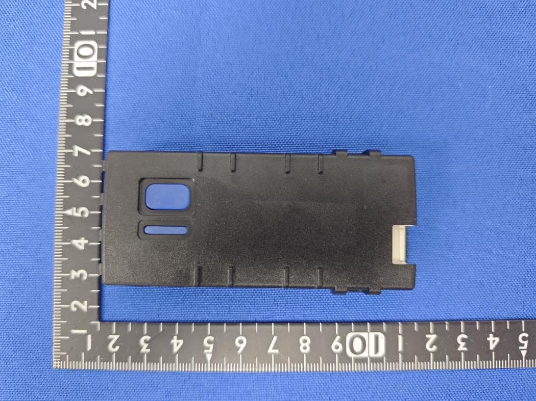
EZS1412VD
Jul 19, 2024KiB Ekey
Equipment Class
DTS - Digital Transmission System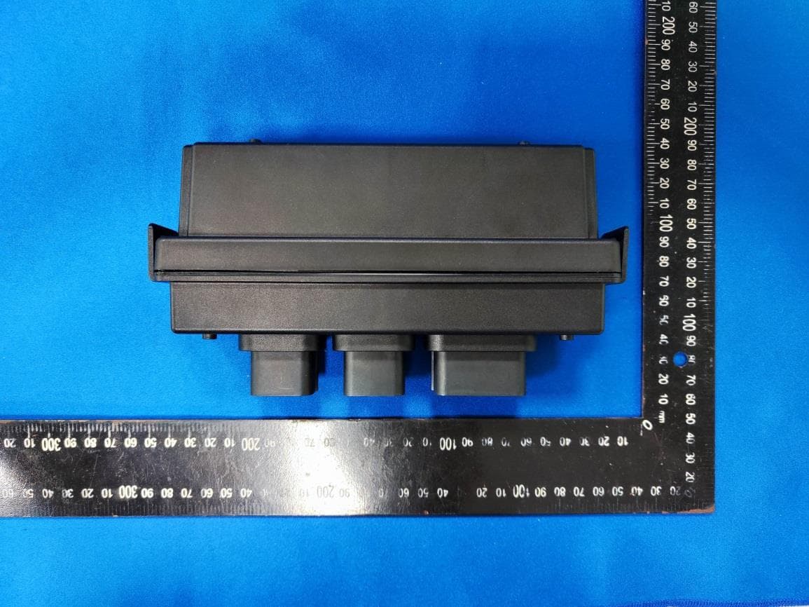
EZS8812
Dec 10, 20228812
Equipment Class
DTS - Digital Transmission System
EZSG7857
Mar 22, 2021915MHz Remote Start Handheld Key fob
Equipment Class
DSS - Part 15 Spread Spectrum Transmitter