EZSDEI7656AOne way transmitter SST car remote starter
Voxx Electronics Corporation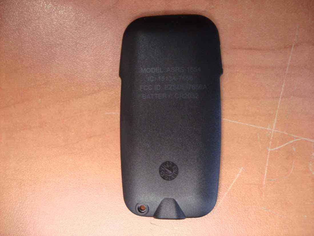
Click to zoom
Application Details
- Equipment Class
- DSS - Part 15 Spread Spectrum Transmitter
- Date of Grant
- Feb 03, 2014
- Application Purpose
- Original Equipment
- Date of Application
- Feb 03, 2014
- Equipment Note
- One way transmitter SST car remote starter
- Frequency Range
- 907.09500000 - 923.83500000
- Company
- Voxx Electronics Corporation
- Country
- United States
Documents & Files
Document Text
Text extracted from the exhibit documents filed with the FCC. Open a document above to read the original.
Users Manual
© 2013 Directed. All Rights Reserved GASRS1554 2013-07 Auto Start ASRS-1554FBK 1-Way Remote User Guide Thank you for purchasing this Auto Start Remote Transmitter. This guide provides a general description of operations for Auto Start Remote Start and Security Systems. LOCK: Locks the DOORS and arms the STARTER KILL (if installed). UNLOCK: Unlocks the DOORS and disarms the STARTER KILL (if installed). Activates the AUX 1 output if Priority Door Access is configured. TRUNK: Opens the TRUNK or activates the AUX 3 output. Note: Trunk option must be installed. START: Remote starts or stops the engine. Gets the system into Cold Weather mode by pressing the AUX button and then pressing and holding the START/STOP button for 3 seconds. AUX: This button serves as a second function button. This button allows assigning different functions to any of the other four buttons. Remote Pairing Procedure Confirmations 1. Press and hold “AUX” button until the remote generates a long beep. The LED will start flashing every 2 seconds for a period of 30 seconds. 2. Turn the key to IGN ON 3. Press release and then press and hold the antenna programming button until the LED start flashing rapidly. The Parking lights will stay ON for 20 seconds. From this point, the installer has 20 seconds to complete steps 4-5. 4. Turn the key to IGN OFF/ON/OFF. The parking light should turn OFF. 5. Press and release lock button. The parking lights will start flashing to confirm successful learning of the remote. 6. Press “AUX” button once OR leave the remote inactive for 30 seconds. Note: To learn the remote to a second car that has the same system, in STEP4, press the TRUNK button instead of the LOCK button. Government Regulations This device complies with Part 15 of FCC rules. Operation is subject to the following two conditions: (1) This device may not cause harmful interference, and (2) This device must accept any interference received, including interference that may cause undesirable operation. This equipment has been tested and found to comply with the limits for a class B digital device, pursuant to Part 15 of the FCC Rules. These limits are designed to provide reasonable protection against harmful interference in a residential installation. This equipment generates and can radiate radio frequency energy and, if not installed and used in accordance with the instruction manual, may cause harmful interference to radio communications. However, there is no guarantee that interference will not occur in a particular installation. If this equipment does cause harmful interference to radio or television, which can be determined by turning the equipment OFF and ON, the user is encouraged to try to correct the interference by one or more of the following measures: • Reorient or relocate the receiving antenna. • Increase the separation between the equipment and receiver. • Connect the equipment into an outlet on a circuit different from that to which the receiver is connected. • Consult the dealer or an experienced radio / TV technician for help. To satisfy FCC RF exposure compliance requirements, this device should be used in hand-held, hand operated configurations only. The device and its antenna must maintain a separation distance of 20 cm or more from the person’s body, except for the hand and wrists, to satisfy RF exposure compliance. This device is designed to be used in a person’s hands and its operating configurations do not support normal transmissions while it is carried in pockets or holsters next to a person’s body. Canada Statements This device complies with Industry Canada licence-exempt RSS standard(s). Operation is subject to the following two conditions: (1) this device may not cause interference, and (2) this device must accept any interference, including interference that may cause undesired operation of the device. Le présent appareil est conforme aux CNR d'Industrie Canada applicables aux appareils radio exempts de licence. L'exploitation est autorisée aux deux conditions suivantes : (1) l'appareil ne doit pas produire de brouillage, et (2) l'utilisateur de l'appareil doit accepter tout brouillage radioélectrique subi, même si le brouillage est susceptible d'en compromettre le fonctionnement. Any changes or modifications not expressly approved by the party responsible for compliance could void the user’s authority to operate the equipment. Les changements ou modifications non approuvés expressément par la partie responsable de la conformité pourrait annuler l'autorité de l'utilisateur à faire fonctionner l'équipement. © 2013 Directed. All Rights Reserved GGSRS1554 2013-07 Auto Start GSRS-1554FBK 1-Way Remote User Guide Thank you for purchasing this Auto Start Remote Transmitter. This guide provides a general description of operations for Auto Start Remote Start and Security Systems. LOCK: Locks the DOORS and arms the STARTER KILL (if installed). UNLOCK: Unlocks the DOORS and disarms the STARTER KILL (if installed). Activates the AUX 1 output if Priority Door Access is configured. TRUNK: Opens the TRUNK or activates the AUX 3 output. Note: Trunk option must be installed. START: Remote starts or stops the engine. Gets the system into Cold Weather mode by pressing the AUX button and then pressing and holding the START/STOP button for 3 seconds. AUX: This button serves as a second function button. This button allows assigning different functions to any of the other four buttons. Remote Pairing Procedure Confirmations 1. Press and hold “AUX” button until the remote generates a long beep. The LED will start flashing every 2 seconds for a period of 30 seconds. 2. Turn the key to IGN ON 3. Press release and then press and hold the antenna programming button until the LED start flashing rapidly. The Parking lights will stay ON for 20 seconds. From this point, the installer has 20 seconds to complete steps 4-5. 4. Turn the key to IGN OFF/ON/OFF. The parking light should turn OFF. 5. Press and release lock b…
Text truncated - open the document above for the full version.
Cover Letter(s)
Jan 16, 2013 Nemko Canada Inc 303 River Road Ottawa, Ontario, Canada K1V 1H2 Attn: Director of Certification Re: Request of Confidentiality Pursuant to Sections 0.457(d)(1)(ii) and 0.459 of the Commission’s Rules, the Applicant hereby requests confidential treatment of information accompanying as outlined below: Schematics Block diagram Operational description All the above for EZSDEI7656A The above materials contain trade secrets and proprietary information not customarily released to the public. The public disclosure of these matters might be harmful to the Applicant and provide unjustified benefits to its competitors. The Applicant understands that pursuant to Rule 0.457(d)(1)(ii), disclosure of this Application and all accompanying documentation will not be made before the date of the Grant for this Application. Sincerely, Minas Minassian Sr. director, hw/rf systems
Cover Letter(s)
Jan 16, 2013 Nemko Canada Inc 303 River Road Ottawa, Ontario, Canada K1V 1H2 Attn: Director of Certification Models: 7656X 7656V OBRS-1554 GSRS-1554 ASRS-1554 Family letter This letter explain that Directed are using different models (Viper 7656V,Clifford 7656X and Autostart OBRS-1554,GSRS-1554,ASRS-1554 )on this product. All this models uses the same (PCB,HW/RF and software ), the only change is the casing cosmetic. Sincerely, Minas Minassian Sr. director, hw/rf systems
ID Label/Location Info
SIDE RUBBER KEYPAD:BLACK+Matte coating ICON COLOR:Cool Gray 5U PRINTING:PMS 426C TOP RUBBER KEYPAD:TRANSLUCENT WHITE BLACK PAINTING+Matte coating LED AREA: LASER ENGRAVING ICON/LOGO COLOR:Cool Gray 5U TOP/BOTTOM HOUSING: NATURAL BLACK 2. Radious will be 0.2 if not specified. 1. Texture is same as MT-11010 BODY MATERIAL : PC/ABS 0.10 0.20 0.40 0.08 A 6~30 120~300 30~120 GRADE DIMENSION UNDER 6 ± 0.40 0.20 0.80 0.16 B ± 0.80 0.40 2.00 0.30 C ± FINISH MATERIAL CODE APPD BY CHK BY SHEET OF UNIT:SCALE: DRN BY DATE NUTEK TITLE SIZE CORPORATION DRAWING NODEPTREV 1-800-274-0200 MODEL: 7656V IC: 1513A-7656 FCC ID: EZSDEI7656A BATTERY: CR2032 1-800-274-0200 MODEL: 7656V IC: 1513A-7656A FCC ID: EZSDEI7656A BATTERY: CR2032 1/29-'14Eric modify screen print 1/29 mail 1 DATE DRN. DESCRIPTION ACC.REV. REVISIONS 1 CENTER SHELL:BLACK+Matte coating ICON COLOR:Cool Gray 5U TOP/BOTTOM HOUSING: NATURAL BLACK LOGO COLOR:Cool Gray 5U TOP RUBBER KEYPAD:BLACK+Matte coating LED AREA: TRANSLUCENT WHITE ICON COLOR:Cool Gray 5U 1-800-274-0200 MODEL: 7656X IC: 1513A-7656 FCC ID: EZSDEI7656A BATTERY: CR2032 REVDEPTDRAWING NO CORPORATION SIZE TITLE NUTEK DATE DRN BY SCALE:UNIT: OFSHEET CHK BY APPD BY CODE MATERIAL FINISH ± C 0.30 2.00 0.40 0.80 ± B 0.16 0.80 0.20 0.40 ± UNDER 6 DIMENSION GRADE 30~120 120~300 6~30 A 0.08 0.40 0.20 0.10 BODY MATERIAL : PC/ABS 1. Texture is same as MT-11010 2. Radious will be 0.2 if not specified. PRINTING:PMS 426C 1-800-274-0200 MODEL: 7656X IC: 1513A-7656A FCC ID: EZSDEI7656A BATTERY: CR2032 1/29-'14Eric modify screen print 1/29 mail 1 DATE DRN. DESCRIPTION ACC.REV. REVISIONS 1 PRINTING:PMS 426C MODEL: ASRS-1554 IC: 1513A-7656 FCC ID: EZSDEI7656A BATTERY: CR2032 2. Radious will be 0.2 if not specified. 1. Texture is same as MT-11010 BODY MATERIAL : PC/ABS NUTEK 0.10 0.20 0.40 0.08 A 6~30 120~300 30~120 GRADE DIMENSION UNDER 6 ± 0.40 0.20 0.80 0.16 B ± 0.80 0.40 2.00 0.30 C ± FINISH MATERIAL CODE APPD BY CHK BY SHEET OF TITLE SIZE UNIT:SCALE: DRN BY DATE CORPORATION DRAWING NODEPTREV TOP/BOTTOM HOUSING: NATURAL BLACK ALUMINUM NAME PLATE:MAT SILVER RUBBER KEYPAD:TRANSLUCENT WHITE BLACK PAINTING+MAT PU coating LED AREA: LASER ENGRAVING ICON COLOR:Cool Gray 5U SIDE BUTTON:NATURAL BLACK ICON ENGRAVING MATERIAL SAME AS 7752V USB PLUG MODEL: ASRS-1554 IC: 1513A-7656A FCC ID: EZSDEI7656A BATTERY: CR2032 REVISIONS REV.ACC. DESCRIPTION DRN.DATE 1 1/29 mail modify screen print Eric1/29-'14 1 PRINTING:PMS 426C MODEL: GSRS-1554 IC: 1513A-7656 FCC ID: EZSDEI7656A BATTERY: CR2032 2. Radious will be 0.2 if not specified. 1. Texture is same as MT-11010 BODY MATERIAL : PC/ABS NUTEK 0.10 0.20 0.40 0.08 A 6~30 120~300 30~120 GRADE DIMENSION UNDER 6 ± 0.40 0.20 0.80 0.16 B ± 0.80 0.40 2.00 0.30 C ± FINISH MATERIAL CODE APPD BY CHK BY SHEET OF TITLE SIZE UNIT:SCALE: DRN BY DATE CORPORATION DRAWING NODEPTREV TOP/BOTTOM HOUSING: NATURAL BLACK ALUMINUM NAME PLATE:MAT SILVER RUBBER KEYPAD:TRANSLUCENT WHITE BLACK PAINTING+MAT PU coating LED AREA: LASER ENGRAVING ICON COLOR:Cool Gray 5U SIDE BUTTON:NATURAL BLACK ICON ENGRAVING MATERIAL SAME AS 7752V USB PLUG 1/29-'14Eric modify screen print 1/29 mail 1 DATE DRN. DESCRIPTION ACC.REV. REVISIONS MODEL: GSRS-1554 IC: 1513A-7656A FCC ID: EZSDEI7656A BATTERY: CR2032 1 NATURAL BLACK MODEL: OBRS-1554 IC: 1513A-7656 FCC ID: EZSDEI7656A BATTERY: CR2032 2. Radious will be 0.2 if not specified. 1. Texture is same as MT-11010 BODY MATERIAL : PC/ABS 0.10 0.20 0.40 0.08 A 6~30 120~300 30~120 GRADE DIMENSION UNDER 6 ± 0.40 0.20 0.80 0.16 B ± 0.80 0.40 2.00 0.30 C ± FINISH MATERIAL CODE APPD BY CHK BY SHEET OF UNIT:SCALE: DRN BY DATE NUTEK TITLE SIZE CORPORATION DRAWING NODEPTREV REVISIONS REV.ACC. DESCRIPTION DRN.DATE 1 TOP RUBBER KEYPAD:TRANSLUCENT WHITE BLACK PAINTING+Matte coating LED AREA: LASER ENGRAVING ICON COLOR:Cool Gray 5U METAL LOOP:CHROME SIDE RUBBER KEYPAD:BLACK+Matte coating ICON COLOR:Cool Gray 5U TOP/BOTTOM HOUSING: BLACK SOFT TOUCH RUBBER PAINT PRINTING:PMS 426C MODEL: OBRS-1554 IC: 1513A-7656A FCC ID: EZSDEI7656A BATTERY: CR2032 1/29 mail modify screen print Eric1/29-'14 1
RF Exposure Info
447498 10 D01 General RF Exposure Guidance v05 4.3.1. Standalone SAR test exclusion considerations 1) The 1-g and 10-g SAR test exclusion thresholds for 100 MHz to 6 GHz at test separation distances ≤ 50 mm are determined by: [(max. power of channel, including tune-up tolerance, mW)/(min. test separation distance, mm)] · [√f(GHz)] ≤ 3.0 for 1-g SAR and ≤ 7.5 for 10-g extremity SAR,16 where f(GHz) is the RF channel transmit frequency in GHz Power and distance are rounded to the nearest mW and mm before calculation17 The result is rounded to one decimal place for comparison The test exclusions are applicable only when the minimum test separation distance is ≤ 50 mm and for transmission frequencies between 100 MHz and 6 GHz. When the minimum test separation distance is < 5 mm, a distance of 5 mm is applied to determine SAR test exclusion. Max power = 6 mW This equipment is a handheld remote control transmitter for use in the 902 – 928 MHz frequency band SAR exclusion Threshold = (6/5)*√0.928=1.16<7.5
Test Report
www.nemko.com Nemko Canada Inc., a testing laboratory, is accredited by the Standards Council of Canada. The tests included in this report are within the scope of this accreditation FCC 15.247 and RSS-210 A8.docx; Date: May 2013 SCC Accredited LAB LAB Accrédité CCN TM ONE WORLDOURAPPROVAL Test report 247504-1TRFWL Date of issue: January 30, 2014 Applicant: DEI Headquarters, Inc. Product: One way transmitter SST car remote starter Model: Model variant: 7656X 7656V, OBRS-1554, GSRS-1554, and ASRS-1554 FCC ID: IC Registration number: EZSDEI7656A 1513A-7656 Specifications: FCC 47 CFR Part 15 Subpart C, §15.247 Operation in the 902–928 MHz, 2400–2483.5 MHz, 5725–5850 MHz RSS-210, Issue 8, December 2010, Annex 8 Frequency Hopping and Digital Modulation Systems Operating in the 902–928 MHz, 2400–2483.5 MHz, and 5725–5850 MHz Bands Report reference ID: 247504-1TRFWL Page 2 of 23 Test location Company name: Nemko Canada Inc. Address: 303 River Road City: Ottawa Province: Ontario Postal code: K1V 1H2 Country: Canada Telephone: +1 613 737 9680 Facsimile: +1 613 737 9691 Toll free: +1 800 563 6336 Website: www.nemko.com Site number: FCC: 176392; IC: 2040A-4 (3 m semi anechoic chamber) Tested by: Kevin Rose, Wireless/EMC Specialist and Daniel Hynes, Senior EMC Specialist Reviewed by: Andrey Adelberg, Senior Wireless/EMC Specialist Date: January 30, 2014 Signature: Limits of responsibility Note that the results contained in this report relate only to the items tested and were obtained in the period between the date of initial receipt of samples and the date of issue of the report. This test report has been completed in accordance with the requirements of ISO/IEC 17025. All results contain in this report are within Nemko Canada’s ISO/IEC 17025 accreditation. Copyright notification Nemko Canada Inc. authorizes the applicant to reproduce this report provided it is reproduced in its entirety and for use by the company’s employees only. Any use which a third party makes of this report, or any reliance on or decisions to be made based on it, are the responsibility of such third parties. Nemko Canada Inc. accepts no responsibility for damages, if any, suffered by any third party as a result of decisions made or actions based on this report. © Nemko Canada Inc. Report reference ID: 247504-1TRFWL Page 3 of 23 Table of contents Table of contents .......................................................................................................................................................................................................... 3 Section 1. Report summary ................................................................................................................................................................................. 4 1.1 Applicant and manufacturer .................................................................................................................................................................................... 4 1.2 Test specifications .................................................................................................................................................................................................... 4 1.3 Test methods ............................................................................................................................................................................................................ 4 1.4 Statement of compliance ......................................................................................................................................................................................... 4 1.5 Exclusions ................................................................................................................................................................................................................. 4 1.6 Test report revision history ...................................................................................................................................................................................... 4 Section 2. Summary of test results ....................................................................................................................................................................... 5 2.1 FCC Part 15 Subpart C, general requirements test results ........................................................................................................................................ 5 2.2 FCC Part 15 Subpart C, intentional radiators test results.......................................................................................................................................... 5 2.3 IC RSS-GEN, Issue 3, test results ............................................................................................................................................................................... 5 2.4 IC RSS-210, Issue 8, test results ................................................................................................................................................................................ 6 Section 3. Equipment under test (EUT) details ..................................................................................................................................................... 7 3.1 Sample information .................................................................................................................................................................................................. 7 3.2 EUT information ....................................................................................................................................................................................................... 7 3.3 Technical information .............................................................................................................................................................................................. 7 …
Text truncated - open the document above for the full version.
Contact Information
Applicant
Joseph A. Santavicca(SVP of Engineering)
Test Firm
Nemko Canada Inc. (Ottawa)Charles Neal
Technical Specifications
| # | Rule Parts | Frequency Range | Power Output |
|---|---|---|---|
| 1 | 15C | 907.095 MHz - 923.835 MHz | 5.66 mW |
Other Applications from Voxx Electronics Corporation
EZS2403VD
Jan 08, 2026BT/NFC Reader
Equipment Class
JAB - Part 15 Class B Digital DeviceEZS6214T
Dec 02, 2024Transceiver
Equipment Class
DSR - Part 15 Remote Control/Security Device Transceiver
EZS1412VD
Jul 19, 2024KiB Ekey
Equipment Class
DTS - Digital Transmission System
EZS8812
Dec 10, 20228812
Equipment Class
DTS - Digital Transmission System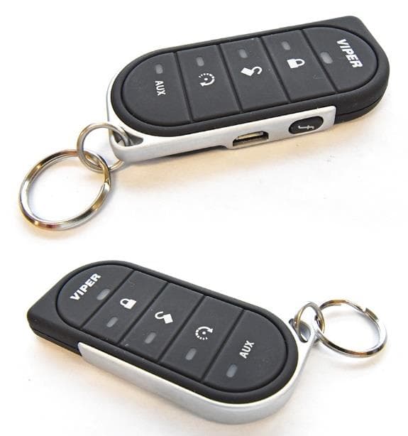
EZSG7857
Mar 22, 2021915MHz Remote Start Handheld Key fob
Equipment Class
DSS - Part 15 Spread Spectrum Transmitter