EZSDEI7703915MHz spread spectrum 25 channels
Voxx Electronics Corporation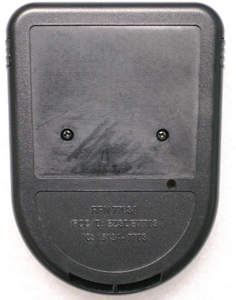
Click to zoom
Application Details
- Equipment Class
- DSS - Part 15 Spread Spectrum Transmitter
- Date of Grant
- Aug 12, 2012
- Application Purpose
- Original Equipment
- Date of Application
- Aug 11, 2012
- Equipment Note
- 915MHz spread spectrum 25 channels
- Frequency Range
- 909.44000000 - 918.50000000
- Company
- Voxx Electronics Corporation
- Country
- United States
Documents & Files
Document Text
Text extracted from the exhibit documents filed with the FCC. Open a document above to read the original.
Users Manual
1 © 2011 Directed Electronics. All rights reserved. User’s Guide 6703A Lot Management System Hub Logo, Directed Electronics w-driven.eps Logo, Directed with designed in USA.eps Logo, Directed with Distributed By.eps Directed Logo Usage Getting Started Connect the hub to the designated computer* using the USB cable provided. The unit is powered via this cable which is also used for data exchange. Position the hub at the highest possible point in an area free of obstructions or interference. Rotate the antenna to the upright position. The hub is used to relay information between the 7703A keypad and the computer. When the hub is connected to power, it initializes by testing each display character in sequence before providing status feedback. Due to the display’s limited character capacity, system status is ab- breviated. These abbreviations are as follows: Display Description UN hub is unplugged, verification is off UN VO hub is unplugged, verification is on PA PC is active, verification is off PA VO PC is active, verification is on NR PC is not responding, verification is off NR VO PC is not responding, verification is on *This designated computer uses proprietary pre-loaded software which enables the hub to transfer data via this system to a remote database. FCC/ID Notice This device complies with Part 15 of the FCC Rules. Op- eration is subject to the following two conditions: (1) This device may not cause harmful interference, and (2) This device must accept any interference received, including interference that may cause undesired operation. This equipment has been tested and found to comply with the limits for Class B Digital Device, pursuant to Part 15 of the FCC Rules. These limits are designed to provide reasonable protection against harmful interference in a residential installation. This equipment generates and can radiate radio frequency energy and, if not installed and used in accordance with the instructions, may cause harmful interference to radio communications. However, there is no guarantee that interference will not occur in a particular installation. If this equipment does cause harm- ful interference to radio or television reception, which can be determined by turning the equipment off and on, the user is encouraged to try to correct the interference by one or more of the following measures. • Reorient or relocate the receiving antenna • Increase the separation between the equipment and receiver • Connect the equipment into an outlet on a circuit dif- ferent from that to which the receiver is connected Antenna Display Mini-USB port 2 © 2011 Directed Electronics. All rights reserved. • Consult the dealer or an experienced radio/TV tech- nician for help Any changes or modifications not expressly approved by the party responsible for compliance could void the user’s authority to operate the equipment. Canada statements: This device complies with Industry Canada licence-exempt RSS standard(s). Operation is subject to the following two conditions: (1) this device may not cause interference, and (2) this device must accept any interference, includ- ing interference that may cause undesired operation of the device. This radio transmitter 6703A & 7703A has been ap- proved by Industry Canada to operate with the antenna types listed below with the maximum permissible gain and required antenna impedance for each antenna type indicated. Antenna types not included in this list, having a gain greater than the maximum gain indicated for that type, are strictly prohibited for use with this device. Le présent appareil est conforme aux CNR d’Industrie Canada applicables aux appareils radio exempts de li- cence. L’exploitation est autorisée aux deux conditions suivantes : (1) l’appareil ne doit pas produire de brouil- lage, et (2) l’utilisateur de l’appareil doit accepter tout brouillage radioélectrique subi, même si le brouillage est susceptible d’en compromettre le fonctionnement. Le présent émetteur radio 6703A et 7703A a été approu- vé par Industrie Canada pour fonctionner avec les types d’antenne énumérés ci-dessous et ayant un gain admis- sible maximal et l’impédance requise pour chaque type d’antenne. Les types d’antenne non inclus dans cette liste, ou dont le gain est supérieur au gain maximal indiqué, sont strictement interdits pour l’exploitation de l’émetteur. When antenna is detachable and RSS-IC Applies This radio transmitter (identify the device by certification number, or model number if Category II) has been ap- proved by Industry Canada to operate with the antenna types listed below with the maximum permissible gain and required antenna impedance for each antenna type indicated. Antenna types not included in this list, having a gain greater than the maximum gain indicated for that type, are strictly prohibited for use with this device. Le présent émetteur radio (identifier le dispositif par son numéro de certification ou son numéro de modèle s’il fait partie du matériel de catégorie I) a été approuvé par In- dustrie Canada pour fonctionner avec les types d’antenne énumérés ci-dessous et ayant un gain admissible maximal et l’impédance requise pour chaque type d’antenne. Les types d’antenne non inclus dans cette liste, ou dont le gain est supérieur au gain maximal indiqué, sont stricte- ment interdits pour l’exploitation de l’émetteur. Antenna S161XX-915R The antenna used for the transmitter must be installed to provide a separation distance of at least 7.87 inches (20 cm) from all persons, and must not be co-located or oper- ating in conjunction with any other antenna or transmitter. L’antenne de l’émetteur doit être installé à une distance d’au moins 7,87 pouces (20 cm) de toutes les personnes, et ne doit pas être placé ou utilisé en conjonction avec toute autre antenne ou tout autre émetteur. This Class B digital apparatus complies with Canadian ICES-003. Cet appareil numérique de la classe B est conforme à la norme NMB-003 du Canada.
Users Manual
Lot load keypad (full guide) Modes and explanations for the lot load keypad and main unit There are four types of keypads; depending on the keypad type is going to determine the user function permissions. SRK‐ Sales Rep Keypad functions: • Command Vehicle: Control the system functions • File Transfer: Transfer the stored information from the keypad to the HUB FIK‐Finance Manager Keypad: • Command Vehicle: Control the system functions • Learn Keypad: Program the keypad to the system • File Transfer: Transfer the stored information from the keypad to the HUB • Set System: Sets the system type; RF Security, RKE Security, Sensor Add, No Sale, Lot Transfer DMK‐Dealer Master Keypad: • Verify Keypads: Verifies SRK and FIK keypads for use when the HUB is inactive (used as backup). EMK‐Expediter Master Keypad: • Command Vehicle: Control the system functions • Learn Keypad: Program the keypad to the system • File Transfer: Transfer the stored information from the keypad to the HUB • Set System: Sets the system type; RF Security, RKE Security, Sensor Add, No Sale, Lot Transfer • Verify Keypads: Verifies SRK and FIK keypads for use when the HUB is inactive (used as backup). The main unit can be placed in multiple modes (for different uses/purposes) by the FIK and EMK keypads only. The following is the description of each mode for operation: Consumer Mode: Places the unit in RF Security, RKE Security, or Sensor Add mode for consumer usability. When the system is in the Consumer Mode you can recall what system the unit is set up as by the LED flashes. The following routine describes how to recall the system type: 1. Turn the ignition On for 1 second, Off for 1 second, On for 1 second, Off for 1 second then back On again and leaving On. 2. The LED will begin to flash a pattern to confirm the mode the unit is set to. Dealer Mode: Used when the vehicle is on the lot and the system is active. Lot Transfer Mode: Places a unit that is currently in Dealer Mode into a modified valet mode until the unit is returned to Dealer Mode. No Sale Mode: Places a unit that is currently in Dealer Mode into a modified valet mode until the unit is returned to Dealer Mode. Initial keypad setup The keypad must be registered and configured by the local Lot Management Program Administrator before it will become operational. 1. Login to the Lot Management Program website 2. Click on Manage Users tab 3. Connect the keypad to the Hub using the supplied USB cable 4. Click on ‘Find Keypad’ button 5. The Keypad ID and previously programmed information is displayed on the screen 6. Enter or change the user information and permissions 7. Click the ‘Configure Keypad’ button 8. The Keypad is configured and ready for use after successful verification Sleep mode and Wake‐up Sleep Mode: To conserve battery life the keypad automatically enters a low power consumption Sleep Mode after an extended period of inactivity. The users name is always displayed in Sleep Mode. Battery status is added to the display when attention is required. “USER NAME” toggles with ‘BATTERY LOW’, ‘CHARGING’ or ‘BATTERY FULL’ to indicate battery status. Wake‐Up: Press any key (except ) to wake up the keypad. Once awake, the keypad may need the User’s PIN and to verify before it will become operational. PIN code: If a PIN code is required “INPUT PIN” ‐ “PRESS ENTER” is displayed on the screen. Input the PIN using the input keys and then press the key. Note; PIN code not required for 1 minute after entering Sleep mode, just press any key (except ). DEALER MODE Is used when the vehicle is on the lot and the system is active. Programming Keypad RF learning (for dealer mode): 1. Open a door and turn the ignition on 2. Press/release once and then press/hold the Valet button 3. The horn/siren will sound once • The button can be released (the unit will exit programming in 30 seconds if no action is performed) 4. Wake up a verified EMK and Input, or confirm and enter, the Dealer ID (DID) 5. Select and enter ‘LEARN KYPD’ from the Function list 6. Input, or confirm and enter, the Vehicle Inventory Number (VIN) 7. Select the System Type as installed and enter to complete learning 8. The horn will emit 1 long chirp and the Keypad will display ‘Successful’ to confirm learning. 9. To exit turn the ignition off, the horn/siren will sound twice to confirm. Notes: • Learning a Keypad sets the system to Dealer mode and deletes all previously learned IDs. • The entered DID & VIN information is saved as the only allowed Keypad ID that can operate the system. • The entered System Type information will be displayed on the Keypad each time the system is operated. • When the system is in dealer mode the feature sets for the system are as follows: Security features OFF Passive arming/locking ON Arm/disarm sounds OFF Ignition controlled locks OFF Panic mode OFF Once the keypad has been programmed to the system, it is ready to be used. To control the system in the vehicle: 1. Wake up a verified Keypad and Input, or confirm and enter, the Pin Number and Dealer ID (DID). 2. Select and enter the ‘FUNCTION LST’. 3. Choose and enter ‘CMND VEHICLE’. 4. Input, or confirm and enter, the Vehicle Inventory Number (VIN) 5. ‘PRESS CMND’ will display on the screen. 6. Press the desired command button on the keypad to control the system. 7. The keypad will display the function chosen and the unit will perform the function. Dealer mode exit: The following procedure is used to exit the dealer mode. 1. Wake up a verified EMK and input, or confirm and enter the DID 2. Select and enter ‘SET SYSTEM’ from the function list 3. Choose the system type in the menu 4. Input, or confirm and enter, the VIN 5. Keypad displays ‘TRANSMITTING’ then ‘PROGRAM ON’ and the horn/siren sounds once confirming entry into programming mode 6. Choose the type of system, press enter 7. Keypad displays ‘TRANSMITTING’ then ‘SUCCESSFUL’ and the horn/siren sounds twice to confirm programming mode has been exited. NOTE: If the keypa…
Text truncated - open the document above for the full version.
Cover Letter(s)
October 12, 2011 Nemko Canada Inc 303 River Road Ottawa, Ontario, Canada K1V 1H2 Attn: Director of Certification FCC ID: EZSDEI7703 Authority to Act as Agent On our behalf, I appoint Alan Laudani of Nemko USA Inc., 2210 Faraday Ave, STE 150, Carlsbad, CA, USA to act as our agent in the preparation of this application for equipment certification. I certify that submitted documents properly describe the device or system for which equipment certification is sought. I also certify that each unit manufactured, imported or marketed, as defined in Federal Communication Commission’s regulations will have affixed to it a label identical to that submitted for approval with this application. For instances where our authorized agent signs the application for certification on our behalf, I acknowledge that all responsibility for complying with the terms and conditions for certification, as specified by Nemko USA Inc, still resides with Minas Minassian, DEI Headquarters,Inc,, 1Viper way, Vista CA 92081, USA. This appointment is in effect until April 1, 2012. Sincerely, Minas Minassian RF Engineering Manager
Cover Letter(s)
October 12, 2011 Nemko Canada Inc 303 River Road Ottawa, Ontario, Canada K1V 1H2 Attn: Director of Certification Re: Request of Confidentiality Pursuant to Sections 0.457(d)(1)(ii) and 0.459 of the Commission’s Rules, the Applicant hereby requests confidential treatment of information accompanying as outlined below: Schematics Block diagram Operational description Parts List All the above for EZSDEI7703 The above materials contain trade secrets and proprietary information not customarily released to the public. The public disclosure of these matters might be harmful to the Applicant and provide unjustified benefits to its competitors. The Applicant understands that pursuant to Rule 0.457(d)(1)(ii), disclosure of this Application and all accompanying documentation will not be made before the date of the Grant for this Application. Sincerely, Minas Minassian RF Engineering Manager
Cover Letter(s)
Model 7703A and Model 6703A differences: Model 7703A is a portable device and model 6703A is a stationary base station based on the same HW. Due to ergonomic requirements, each model has a unique antenna. Each antenna has a unique set of RF matching component values. All active, frequency defining, oscillator and power generating circuits as well as the PCB are identical. Here are the differences; MODEL 6703A (HUB) Model 7703A (KEY PAD) L1 NC 8.7nH L13 NC 8.2nH L14 10nH NC C15 3pF 100pF C17 NC 5.1pF U1 NC 25LC256 R40 NC 100K R41 NC 100K U6 AT25DF641 NC R44 100K NC R45 100K NC Antenna Nearson S161XX-915R Trace The L1, L13, L14, C15, C17 change from the Key pad to Hub to allow perfect matching 50ohm between Antennas impedance and the Saw filter impedance. Base in the different data it need to be loader in the Hub and Key pad, the both support two different EEPROM , AT25DF641 for Hub and 25LC256 for Keypad. R40,R41 are used to support U6 EEPROM in the Hub model , and R44and R45 are used to support the Key pad model. This EEPROM circuitry has nothing to do with RF or RF control. Schematic 3 and Schematic 2 shows and mention those differences, with clear note inside.
External Photos
Model 6703A Model 7703A The Hub support a external antenna, this external antenna use a reverse technology with that work with a reverse technology connector this will not allow using the standard antenna in the market : RF connector Antenna Antenna: Nearson S161XX-915R
RF Exposure Info
Prediction of MPE limit at a given distance S = power density P = power input to the antenna G = antenna gain R = distance Conducted output power:7.00(dBm) 5(mW) 0.005(W) Antenna gain:2.5(dBi) Maximum antenna gain:1.78(numeric) EIRP0.00891(W) Distance:20(cm) Duty Cycle:100(%) Frequency:918.5(MHz) MPE Limit:0.612(mW/cm^2) Power density:0.00177(mW/cm^2) 0.0177(W/m^2) Margin25.4(dB) 2 4R PG S p =
Test Report
Nemko USA, Inc. FCC Part 15 Subpart C, 15.247 : 10/08/2012 CERTIFICATION TEST REPORT Report Number: 2012 02164553 FCC Project Number: 1023311 Nex Number: 164553 Applicant: DEI HEADQUARTERS INC. 1 VIPER WAY Vista, CA 92081 Equipment Under Test (EUT): HAND HELD UNIT : MODEL 7703A HUB: MODEL 6703A, FCC ID: EZSDEI7703 IC: 1513A-7703 In Accordance With: FCC Part 15 Subpart C, 15.247 IC RSS-210 Issue 8 December 2010 IC RSS-Gen Issue 3 December 2010 Tested By: Nemko USA Inc. 11696 Sorrento Valley Road, Suite F San Diego, CA 92121 Authorized By: Alan Laudani, EMC/RF Test Engineer Date: A UGUST 1, 2012 Total Number of Pages: 52 Nemko USA, Inc. 2210 Faraday Avenue, Suite 150, Carlsbad, CA 92008 Phone (760) 444-3500 Fax (760) 444-3005 IC: 1513A-7703 Report Number: 2007 076353-2 FCC FCC ID: EZSDEI7703 Specification: FCC Part 15 Subpart C, 15.247 Page 2 of 52 Section 1. Summary of Test Results 1.1 General All measurements are traceable to national standards These tests were conducted on a sample of the equipment for the purpose of demonstrating compliance with Part 15; Subpart C and RSS-210, Issue 8 December 2010. Radiated tests were conducted is accordance with ANSI C63.4-2003. Radiated emissions are made on an open area test site. A description of the test facility is on file with the FCC and IC. The assessment summary is as follows: Apparatus Assessed: 6703A, 7703A Specifications: FCC Part 15 Subpart C, 15.247 IC RSS-210 Issue 8 December 2010 Date Received in Laboratory: M ARCH 18, 2011 TO AUGUST 1, 2012 Compliance Status: Complies Exclusions: None Non-compliances: None Nemko USA, Inc. 2210 Faraday Avenue, Suite 150, Carlsbad, CA 92008 Phone (760) 444-3500 Fax (760) 444-3005 IC: 1513A-7703 Report Number: 2007 076353-2 FCC FCC ID: EZSDEI7703 Specification: FCC Part 15 Subpart C, 15.247 Page 3 of 52 1.2 Report Release History: REVISION DATE COMMENTS - AUGUST 1, 2012 Prepared By: Alan Laudani - AUGUST 1, 2012 Initial Release: Alan Laudani Note that the results contained in this report relate only to the items tested and were obtained in the period between the date of initial receipt of samples and the date of issue of the report. This test report has been completed in accordance with the requirements of ISO/IEC 17025. Nemko USA Inc. authorizes the applicant to reproduce this report provided it is reproduced in its entirety and for use by the company’s employees only. Any use which a third party makes of this report, or any reliance on or decisions to be made based on it, are the responsibility of such third parties. Nemko USA Inc. accepts no responsibility for damages, if any, suffered by any third party as a result of decisions made or actions based on this report. TESTED BY: Date: AUGUST 1, 2012 Alan Laudani, EMC Test Engineer Nemko USA, Inc. 2210 Faraday Avenue, Suite 150, Carlsbad, CA 92008 Phone (760) 444-3500 Fax (760) 444-3005 IC: 1513A-7703 Report Number: 2007 076353-2 FCC FCC ID: EZSDEI7703 Specification: FCC Part 15 Subpart C, 15.247 Page 4 of 52 TABLE OF CONTENTS Section 1. Summary of Test Results ....................................................................... 2 1.1 General ........................................................................................................................................ 2 1.2 Report Release History: ............................................................................................................... 3 Section 2: Equipment Under Test ................................................................................ 5 2.1 Product Identification ................................................................................................................... 5 2.2 Theory of Operation ..................................................................................................................... 5 2.3 Technical Specifications of the EUT ............................................................................................ 6 Section 3: Test Conditions ........................................................................................... 7 3.1 Specifications ............................................................................................................................... 7 3.3 Test Environment ......................................................................................................................... 7 3.4 Test Equipment ............................................................................................................................ 8 Section 4: Observations ............................................................................................... 9 4.1 Modifications Performed During Assessment .............................................................................. 9 4.2 Record Of Technical Judgments ................................................................................................. 9 4.3 EUT Parameters Affecting Compliance ....................................................................................... 9 4.4 Deviations From Laboratory Test Procedures ............................................................................. 9 4.5 Test Deleted ................................................................................................................................ 9 4.6 Additional Observations ............................................................................................................... 9 Section 5: Results Summary ...................................................................................... 10 5.1 Test Results ............................................................................................................................... 10 Appendix A: Test Results ......................................................................................... A11 Power Line Conducted Emissions ............................................................................................................ A11 20 dB Bandwidth ........…
Text truncated - open the document above for the full version.
Test Setup Photos
MODEL 7703A (remote) radiated emissions MODEL 7703A (remote) radiated emissions MODEL 6703A (HUB), keypad required for changing frequencies, test mode. radiated emissions MODEL 6703A (HUB), keypad required for changing frequencies, test mode. radiated emissions AC power line conducted emissions, MODEL 6703A, no enclosure MODEL 6703A (HUB), keypad required for changing frequencies, test mode. Additional setups – Carlsbad Model 7703A (KEY PAD) MODEL 6703A (HUB)
Contact Information
Applicant
Joseph A. Santavicca(SVP of Engineering)
Test Firm
Nemko USA, Inc. - San Diego EMC DivisionJan Blomgren
[email protected]760-444-3500
Technical Specifications
| # | Rule Parts | Frequency Range | Power Output |
|---|---|---|---|
| 1 | 15C | 909.44 MHz - 918.5 MHz | 5.00 mW |
Other Applications from Voxx Electronics Corporation
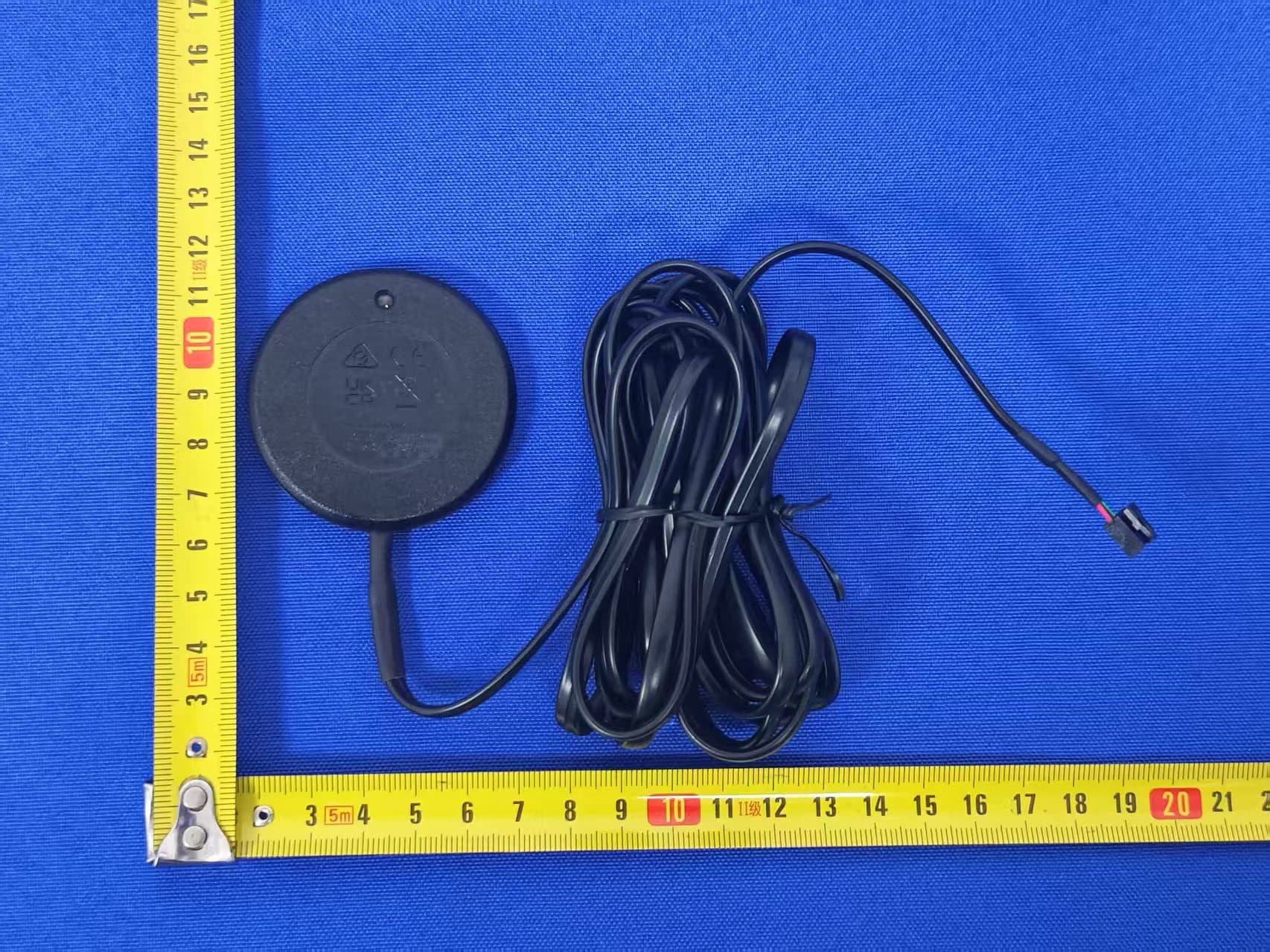
EZS2403VD
Jan 08, 2026BT/NFC Reader
Equipment Class
JAB - Part 15 Class B Digital DeviceEZS6214T
Dec 02, 2024Transceiver
Equipment Class
DSR - Part 15 Remote Control/Security Device Transceiver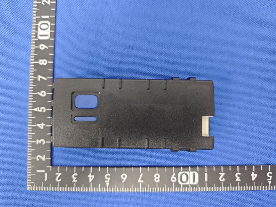
EZS1412VD
Jul 19, 2024KiB Ekey
Equipment Class
DTS - Digital Transmission System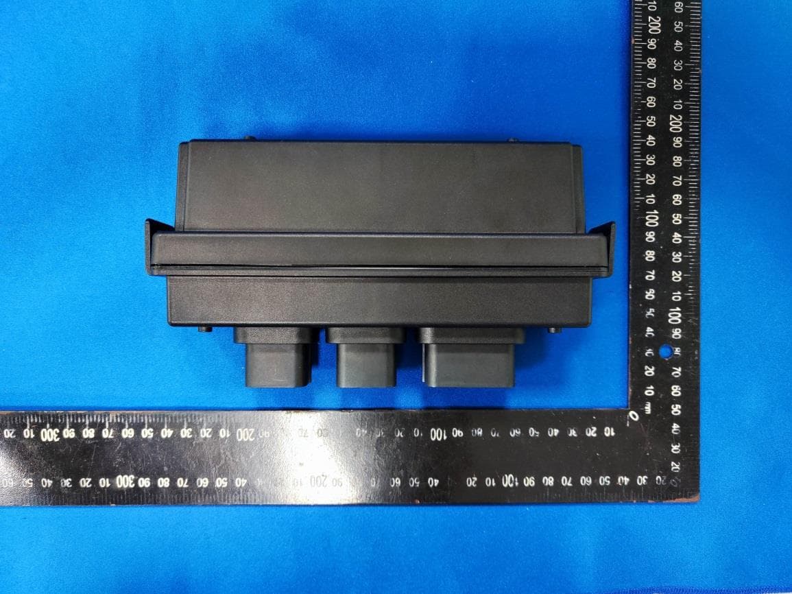
EZS8812
Dec 10, 20228812
Equipment Class
DTS - Digital Transmission System
EZSG7857
Mar 22, 2021915MHz Remote Start Handheld Key fob
Equipment Class
DSS - Part 15 Spread Spectrum Transmitter