EZSDEIINKEYCar Alarm Remote Transmitter
Voxx Electronics Corporation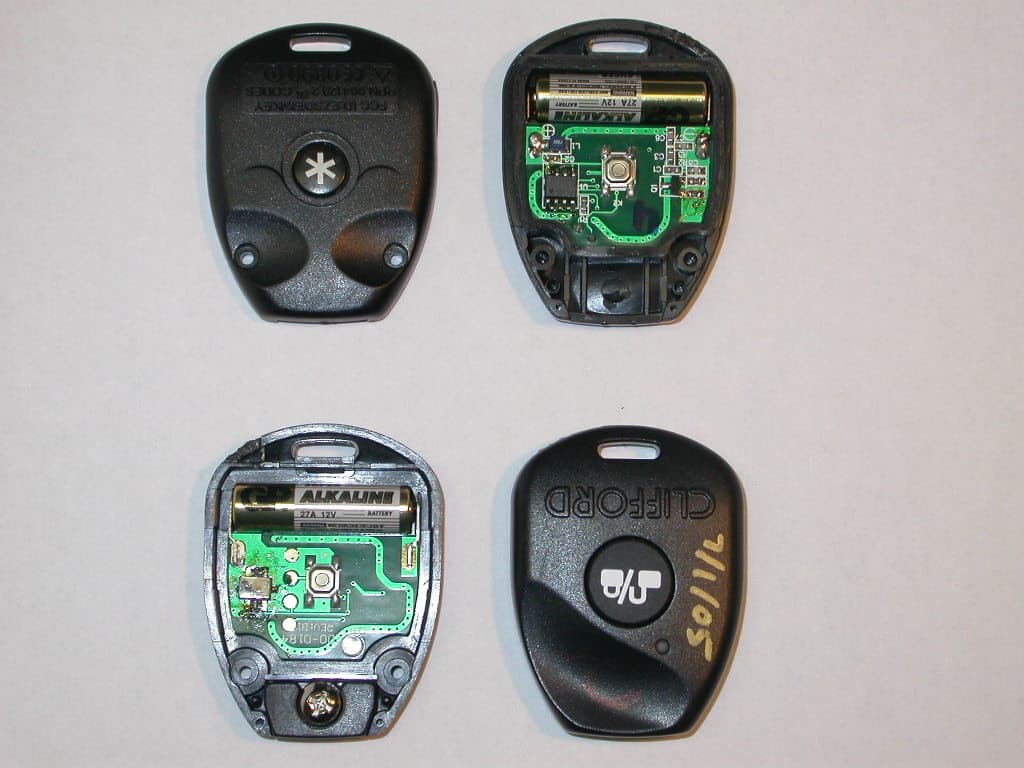
Click to zoom
Application Details
- Equipment Class
- DSC - Part 15 Security/Remote Control Transmitter
- Date of Grant
- Nov 01, 2005
- Application Purpose
- Original Equipment
- Date of Application
- Sep 26, 2005
- Equipment Note
- Car Alarm Remote Transmitter
- Frequency Range
- 433.92000000 - 433.92000000
- Company
- Voxx Electronics Corporation
- Country
- United States
Documents & Files
Document Text
Text extracted from the exhibit documents filed with the FCC. Open a document above to read the original.
Users Manual
The Science of Security ™ CClliiffffoorrdd PN 904120 Compatible with the following systems: GGPP11000000TT ((GG55)) AArrrrooww 55 ((GG55)) PPoollaarriiss 44 ((GG44)) CCyybbeerr 22 ((GG44)) AAccee 220000 ((GG44)) AArrrrooww 33 ((GG44)) MMaattrriixx 11 MADE IN CHINA © 2005 Directed Electronics, Inc. Vista CA 92081 All rights reserved. P/N 904120 04-05 1.IGNITION ON:Place the key into the ignition and turn to the ON position or start the engine. 2.ENTER PIN NUMBER: Enter your PIN number using the Plainview 2 valet switch. Note:The Factory default PIN number is written on the back of the system owner’s guide. 3.PRESS/HOLD/RELEASE:Immediately PRESS and HOLD the * button until you hear one chirp and the Status LED turns on, then RELEASE the * button. 4.PRESS/RELEASE:PRESS and RELEASE the "blank" button once. Pause until you hear one chirp. 5.PRESS/RELEASE:PRESS and RELEASE the * button once. The siren will chirp once as you push the button. 6.TRANSMIT:Press the button on you new transmitter. The siren will chirp once to confirm it has received the transmission. 7.TRANSMIT AGAIN:Press the button a second time. The siren will chirp twice to confirm it has learned your new transmitter. 8.IGNITION OFF:Turn the ignition off and remove the key: The alarm will chirp three times to indicate exiting transmitter learn routine. 9.TEST TRANSMITTER:Press the button to verify that the transmitter is operating the alarm system. Note:This transmitter auto-learn routine is applicable to specific system/transmitter combinations, use the following reference guide or consult your local Clifford dealer for your particular application 904120 transmitter: GP1000T/Arrow 5/Arrow 3/Cyber 2 904065 transmitter: Arrow 5 /Arrow 3 / Cyber 2 904100 transmitter: Concept 100 / Concept 450/ Intelliguard 6000 / Cyber 4 904075 transmitter: All other systems This device complies with Part 15 of FCC rules. Operation is subject to the following conditions: (1) This device may not cause harmful interference, and (2) This device must accept any interference received, including interference that may cause unde- sired operation. Changes or modifications not expressly approved by the party responsible for compliance could void the user's authority to operate this device. 22 BBuuttttoonn,, IInn--KKeeyy RReeppllaacceemmeenntt TTrraannssmmiitttteerr PN 904120 To program your new transmitter:
Block Diagram
1234 A B C D 4 321 D C B A T42 A Title: Size:Num ber: Revision: Date C ode: File: Sheet of Dr wn By X:\Develop ment\D2004 \401-4 146 Cl ifford Thatcham MC alarm\Project Plan\SCH_PCB\GP5 00.DDB - Do cumen ts\Block D 11 A Directed Electronics Inc. One Viper Way V is ta , C A 92081 Phone: 760-598-6200 Fa x: 760-598-6400 Appd By Chkd By Da te Da te Da te 433.92 MHz Blue LED BAT+ (Cl i p) BAT- (PCB) 12 V Ba ttery SW2 SW1 EncoderRF Oscillator PCB Antenna Mi n as Mi nas si an 09/ 13/ 2 005
Cover Letter(s)
Tuesday, September 13, 2005 Chief, Equipment Approval Services Federal Communications Commission P.O. Box 358315 Pittsburgh, PA 15251-5315 Re: Request of Confidentiality Pursuant to Sections 0.457(d)(1)(ii) and 0.459 of the Commission’s Rules, the Applicant hereby requests confidential treatment of information accompanying as outlined below: Schematics for EZSDEIINKEY. The above materials contain trade secrets and proprietary information not customarily released to the public. The public disclosure of these matters might be harmful to the Applicant and provide unjustified benefits to its competitors. The Applicant understands that pursuant to Rule 0.457(d)(1)(ii), disclosure of this Application and all accompanying documentation will not be made before the date of the Grant for this Application. Sincerely, Minas Minassian RF Engineering Manager
External Photos
Photo 1 Top and bottom internal Photo 2 Assembled case top side Photo 3 Assembled case bottom side Photo 6 Rubber keypad top side Photo 7 Rubber keypad bottom side Photo 8 Complete Mechanicals
ID Label/Location Info
FCC ID Label Location – Rear of Case 1. Label is on separate piece of paper and included with transmitter.
Internal Photos
Photo 1 Top and bottom internal Photo 4 PCB top side Photo 5 PCB bottom side Photo 8 Complete Mechanicals
Operational Description
EUT is operated by pressing one of the momentary switches. The switch makes contact on the PCB which inputs voltage to one of the DIGITAL ENCODERS inputs. The DIGITAL ENCODER sends a Pulse Width Modulated signal to the RF Oscillator section. The RF Oscillator section transmits the signal at 433.92MHz via a PCB antenna.
Contact Information
Applicant
Joseph A. Santavicca(SVP of Engineering)
Test Firm
TUV America Inc.Jim Owen
Technical Specifications
| # | Rule Parts | Frequency Range | Power Output |
|---|---|---|---|
| 1 | 15.231 | 433.92 MHz - 433.92 MHz | - |
Other Applications from Voxx Electronics Corporation
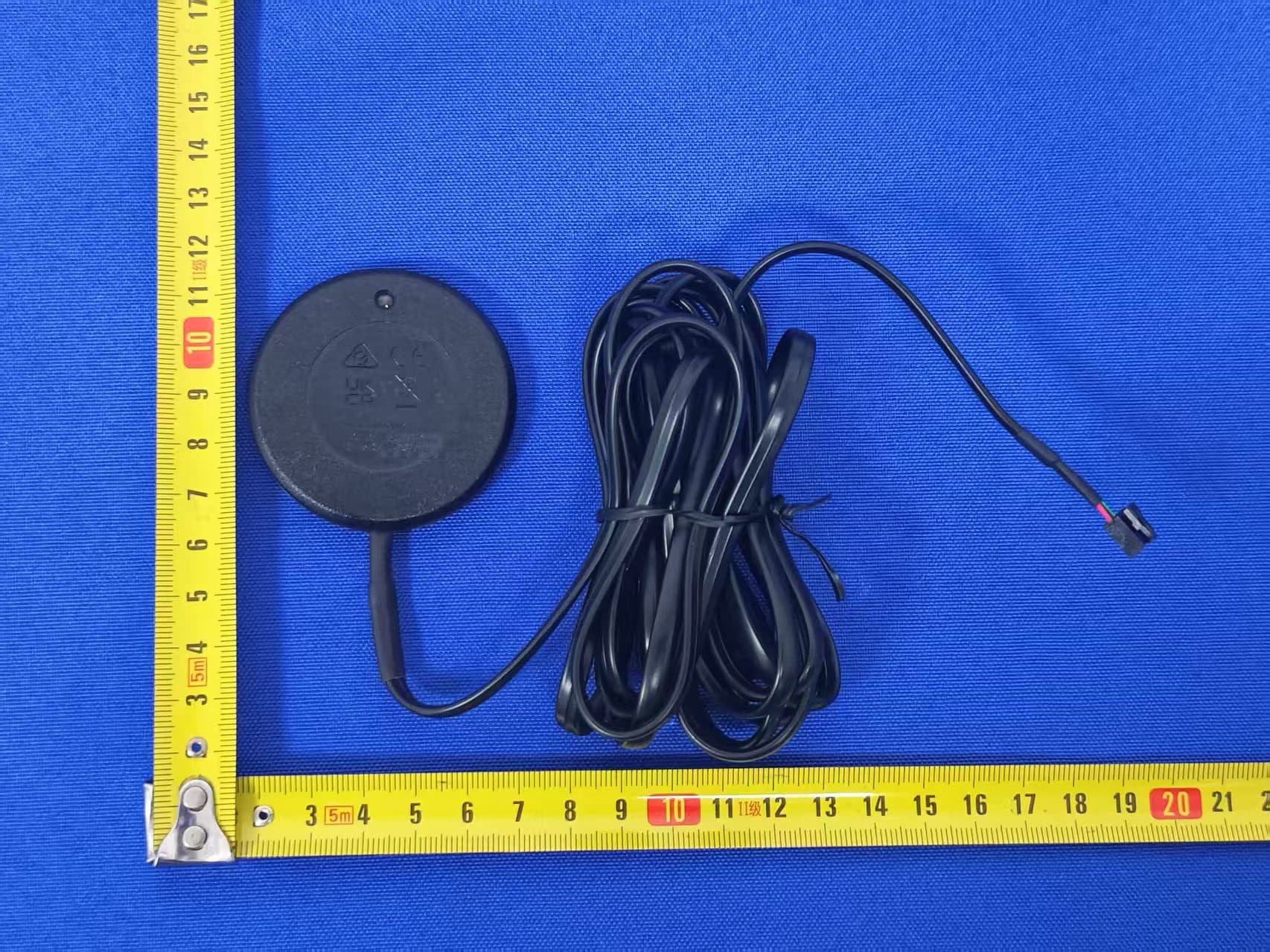
EZS2403VD
Jan 08, 2026BT/NFC Reader
Equipment Class
JAB - Part 15 Class B Digital DeviceEZS6214T
Dec 02, 2024Transceiver
Equipment Class
DSR - Part 15 Remote Control/Security Device Transceiver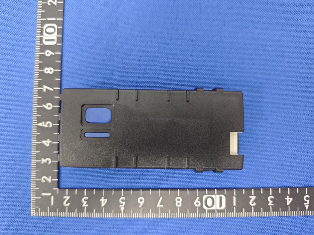
EZS1412VD
Jul 19, 2024KiB Ekey
Equipment Class
DTS - Digital Transmission System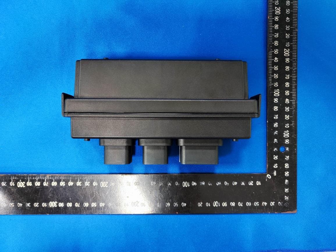
EZS8812
Dec 10, 20228812
Equipment Class
DTS - Digital Transmission System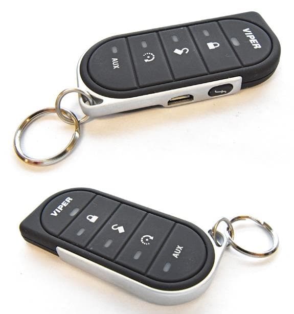
EZSG7857
Mar 22, 2021915MHz Remote Start Handheld Key fob
Equipment Class
DSS - Part 15 Spread Spectrum Transmitter