EZSRADAR2Radar 2
Voxx Electronics Corporation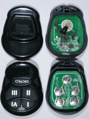
Click to zoom
Application Details
- Equipment Class
- DSC - Part 15 Security/Remote Control Transmitter
- Date of Grant
- Mar 17, 2003
- Application Purpose
- Original Equipment
- Date of Application
- Feb 12, 2003
- Equipment Note
- Radar 2
- Frequency Range
- 433.96000000 - 433.96000000
- Company
- Voxx Electronics Corporation
- Country
- United States
Documents & Files
Document Text
Text extracted from the exhibit documents filed with the FCC. Open a document above to read the original.
Users Manual
The Science of Security ™ 11 66 CC hh aa nn nn ee ll ,, 55 BB uu tt tt oo nn ,, AA CC GG RR ee pp ll aa cc ee mm ee nn tt TT rr aa nn ss mm ii tt tt ee rr PN 904075 Compatible with thefollowing systems: AA vv aa nn tt gg uu aa rr dd 55 (( GG 55 )) SS oo ll aa rr ii ss 55 (( GG 55 )) II nn tt ee ll ll ii GG uu aa rr dd 88 55 00 (( GG 55 )) II nn tt ee ll ll ii GG uu aa rr dd 77 55 00 (( GG 55 )) CC oo nn cc ee pp tt 55 55 00 (( GG 55 )) TT aa zz oo rr 44 (( GG 44 )) BB uu ll ll ee tt 44 (( GG 44 )) MADE IN TAIWAN © 2002 Directed Electronics, Inc. Vista CA 92083 All rights reserved. P/N 904075 11/02 1. IGNITION ON: Place the key into the ignition and turn to the ON position or start the engine. 2. ENTER PIN NUMBER : Enter your PIN number using the Plainview 2 valet switch. Note: The Factory default PIN number is 2 and can be entered by pressing the * button twice then the "blank" button once of the Plainview 2 valet switch. 3. PRESS/HOLD/RELEASE: Immediately PRESS and HOLD the * button until you hear one chirp and the Status LED turns on, then RELEASE the * button. 4. PRESS/RELEASE: PRESS and RELEASE the "blank" button once. Pause until you hear onechirp. 5. PRESS/RELEASE: PRESS and RELEASE the * button once. The siren will chirp once as you push the button. 6. TRANSMIT: Press the button on your new transmitter. The siren will chirp once to confirm ithas received the transmission. 7. TRANSMIT AGAIN: Press the button a second time. The siren will chirp twice to confirmit has learned your new transmitter. 8. IGNITION OFF: Turn the ignition off and remove the key: The alarm will chirp three times toindicate exiting transmitter learn routine. 9. TEST TRANSMITTER: Press the button to verify that the transmitter is operating thealarm system. Note: This transmitter auto-learn routine is applicable to specific system/transmitter combinations, use thefollowing reference guide or consult your localClifford dealer for your particular application904065 transmitter: Arrow 5 /Arrow 3 / Cyber 2 904100 transmitter: Concept 100 / Concept 450/ Intelliguard 6000 / Cyber 4 904075 transmitter: All other systems This device complies with Part 15 of FCC rules.Operation is subject to the following conditions: (1)This device may not cause harmful interference, and(2) This device must accept any interferencereceived, including interference that may causeundesired operation. Changes or modifications notexpressly approved by the party responsible forcompliance could void the user's authority tooperate this device. 11 66 CC hh aa nn nn ee ll ,, 55 BB uu tt tt oo nn ,, AA CC GG RR ee pp ll aa cc ee mm ee nn tt TT rr aa nn ss mm ii tt tt ee rr PN 904075 To program your new transmitter: TM G5 Blister card.qxd 1/30/2003 9:57 AM Page 1
Block Diagram
1234 A B C D 4321 D C B A RADAR2 A Title: Size:Number:Revision: Date Code: File: Sheet of Drwn By X:\FCC\Radar2 (Rev. 2)\Docs for TUV\Radar2 block.ddb - Documents\Radar2 block.Sch 11 A Directed Electronics Inc. One Viper Way Vista, CA 92083 Phone: 760-598-6200 Fax: 760-598-6400 DTBK Appd By Chkd By Date Date Date 433.92 MHz Blue LED BAT+(Clip) BAT- (PCB) 6V Battery SW2 DOME SW1 DOME SW3 DOME SW4 DOME EncoderRF Oscillator PCB Antenna Minas Minassian 01/15/2003 (2 x 3V) SW5 DOME
Cover Letter(s)
Friday, February 07, 2003 Chief, Equipment Approval Services Federal Communications Commission P.O. Box 358315 Pittsburgh, PA 15251-5315 Dear Sir or Madam: We, (Name and Address of Firm), hereby authorize TÜV Product Service (10040 Mesa Rim Road, San Diego, CA 92121, Tel. (619) 546-3999) to act as our agent in all matters relating to applications for equipment authorization, including the signing of all documents relating to these matters. I further certify that the applicant nor any party to the application is subject to a denial of Federal benefits, that includes FCC benefits, pursuant to Section 5301 of the Anti-Drug Abuse Act of 1988, 21 U.S.C. Section 862. This authorization expires on Friday, February 07, 2004. Sincerely, Vice President of Engineering (760) 598-6200 (760) 598-6400
External Photos
MATT BLACK FINISH CASE TOP AND BOTTOM OF RUBBER KEYPAD USED FOR MATT FINISH KEYPAD USED FOR CARBON FINISH TOP OF CARBON AND MATT FINISH BOTTOM OF CARBON AND MATT FINISH
Internal Photos
MATT BLACK FINISH CASE FRONT OF RADAR2 PCB BACK OF RADAR2 PCB
Operational Description
EUT is operated by pressing one of the momentary switches. The switch makes contact on the PCB which inputs voltage to one of the DIGITAL ENCODERS inputs. The DIGITAL ENCODER sends a Pulse Width Modulated signal to the RF Oscillator section. The RF Oscillator section transmits the signal at 433.92MHz via a PCB antenna.
Test Report
TÜV AMERICA, INC. 10040 Mesa Rim Road San Diego, CA 92121-2912 Phone 858 546 3999 FAX 858 546 0364 Report No. SC300367-03 Page 1 of 16 Rev.No 1.0 MEASUREMENT AND TECHNICAL REPORT DIRECTED ELECTRONICS INCORPORATED 2560 Progress Street Vista, CA 92083 DATE: 31 January 2003 This Report Concerns: Original Grant: X Class II Change: Equipment Type: Radar 2, Models 904070 and 904075 Deferred grant requested per 47 CFR 0.457(d)(1)(ii)? Yes: Defer until: No: X Company Name agrees to notify the Commission by: N/A of the intended date of announcement of the product so that the grant can be issued on that date. Transition Rules Request per 15.37? Yes: No: X* (*) FCC Part 15, Paragraph(s) 15.231(a), 15.231(b), 15.231(c) Report Prepared by: TÜV AMERICA, INC 10040 Mesa Rim Road San Diego, CA 92121-2912 Phone: 858 546 3999 Fax: 858 546 0364 TÜV AMERICA, INC. 10040 Mesa Rim Road San Diego, CA 92121-2912 Phone 858 546 3999 FAX 858 546 0364 Report No. SC300367-03 Page 2 of 16 Rev.No 1.0 TABLE OF CONTENTS Pages 1.0 GENERAL INFORMATION 3 - 6 1.1 Product Description 3 - 5 1.2 Related Submittal Grant 6 1.3 Tested System Details 6 1.4 Test Methodology 6 1.5 Test Facility 6 1.6 Part 2 Requirements 6 2.0 SYSTEM TEST CONFIGURATION 7 2.1 Justification 7 2.2 EUT Exercise Software 7 2.3 Special Accessories 7 2.4 Equipment Modifications 7 2.5 Configuration of Test System 7 3.0 DEACTIVATION EQUIPMENT/DATA RADIATED SPURIOUS EMISSIONS EQUIPMENT/DATA DUTY CYCLE MEASUREMENTS EQUIPMENT/DATA EMISSIONS BANDWIDTH EQUIPMENT/DATA 8 - 15 4.0 ATTESTATION STATEMENT 16 TÜV AMERICA, INC. 10040 Mesa Rim Road San Diego, CA 92121-2912 Phone 858 546 3999 FAX 858 546 0364 Report No. SC300367-03 Page 3 of 16 Rev.No 1.0 1.0 GENERAL INFORMATION 1.1 Product Description General Equipment Description -- NOTE: This information will be input into your test report as shown below. EUT Description: Keyfob Transmitter EUT Name: Radar 2 Model No.: 904070 and 904075 Serial No.: -- Product Options: -- Configurations to be tested: Normal Emissions Power Requirements Regulations require testing to be performed at typical power ratings in the countries of intended use. (i.e., European power is typically 230 VAC 50 Hz or 400 VAC 50 Hz, single and three phase, respectively) Voltage: 6V (If battery powered, make sure battery life is sufficient to complete testing.) # of Phases: -- Current (Amps/phase(max)): -- Current (Amps/phase(nominal)): -- Other: Battery operated by (2) CR2025 Battery Cells Typical Installation and/or Operating Environment (ie. Hospital, Small Business, Industrial/Factory, etc.) Automotive electronics, inc EUT Power Cable: N/A EUT Specifications and Requirements Length: Width: Height: Weight: EUT Interface Ports and Cables: N/A EUT Operating Modes to be Tested : N/A EUT System Components : N/A TÜV AMERICA, INC. 10040 Mesa Rim Road San Diego, CA 92121-2912 Phone 858 546 3999 FAX 858 546 0364 Report No. SC300367-03 Page 4 of 16 Rev.No 1.0 1.1 Product Description (continued) Support Equipment : N/A Power Supply: N/A Power Line Filters: N/A Critical EMI Components (Capacitors, ferrites, etc.): N/A EMC Critical Detail -- : N/A TÜV AMERICA, INC. 10040 Mesa Rim Road San Diego, CA 92121-2912 Phone 858 546 3999 FAX 858 546 0364 Report No. SC300367-03 Page 5 of 16 Rev.No 1.0 1.1 Product Description (continued) 1. Learn routine for replacement transmitters The Radar2 transmitter will be programmed-in to work with automotive security / convenience systems. These systems all use the same learn routine to program-in the replacement transmitter. Using two momentary switches (2) in the vehicle (valet switch) and the ignition key, the user will input a security code that allows access to the system’s programming mode. Once in program mode, the user will need to transmit, pause and transmit again in order to program the transmitter into the system. A single continuous transmission will not work so a secondary transmitter in the vicinity of the receiver will not be programmed-in. The user has a maximum of 60 seconds to program up to four transmitters into the system. The system confirms the programming of transmitters via a series of audible chirps. The user can exit the programming mode at any time simply by removing the ignition. Exiting the learn routine is confirmed by a series of chirps. Directed electronics provides a tool called the “Wizard” to our authorized dealers. This tool allows to verify how many transmitters are programmed-in or to delete all currently programmed transmitters in the alarm system. This is accomplished through a temporary serial connection from the “Wizard” tool to the alarm system. And finally, Directed Electronics Radar2 compatible alarm systems will only learn Directed Electronics Radar2 transmitters. Our systems provide interactive responses from the alarm system while programming replacement transmitters in. Tools provided from Directed Electronics to our authorized installers allow them to monitor what has been programmed-in the alarm system. Given these features and tools, the likelihood of having a transmitter get programmed-in unintentionally and not be known is very remote to impossible. 2. System transmission frequency range This transmitter is a single frequency device. It’s SAW resonator based and the transmission frequency is determined by the SAW resonator. The resonator used in the Radar2 has a center frequency of 433.92 MHz +/-75 KHz. This means the single transmission frequency will always be locked at 433.92MHz only with a +/-75 KHz tolerance for its center. Furthermore, the receivers operated by this transmitter are single band receivers tuned to 433.92MHz and only capable of receiving this frequency. 3. Data transmission duty cycle description The Radar2 is a data transmission device. Their protocol consists of 12 preamble bits (400us each) and 66 data bits (400us or 800us each, they are random) for a total of 78 bits. So the calculation for the duty cycle becomes: (12 x 400us)+(66x800us)= 57.60ms within a …
Text truncated - open the document above for the full version.
Contact Information
Applicant
Joseph A. Santavicca(SVP of Engineering)
Test Firm
TUV AmericaJames Owen
Technical Specifications
| # | Rule Parts | Frequency Range | Power Output |
|---|---|---|---|
| 1 | 15.231 | 433.96 MHz - 433.96 MHz | - |
Other Applications from Voxx Electronics Corporation
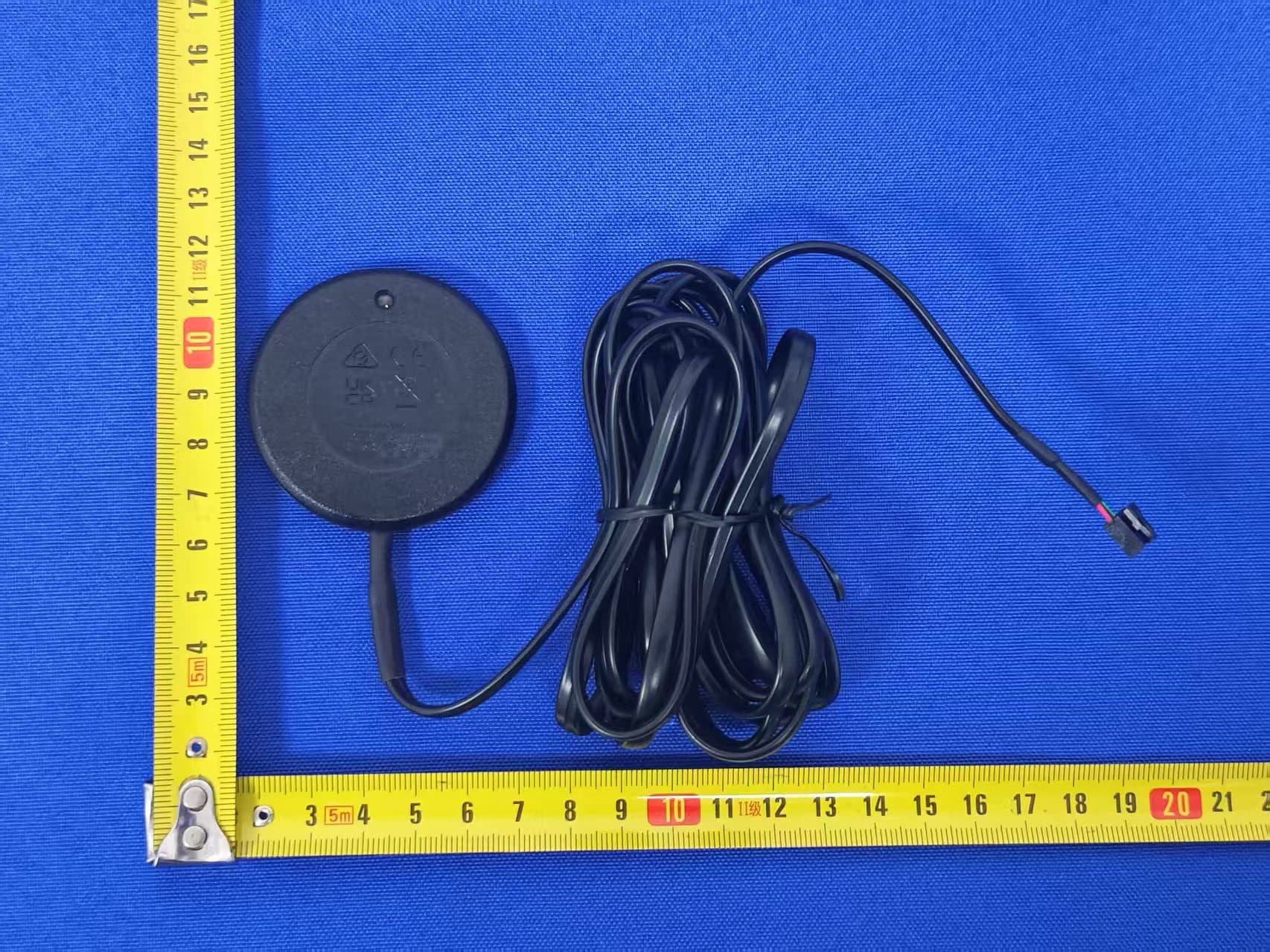
EZS2403VD
Jan 08, 2026BT/NFC Reader
Equipment Class
JAB - Part 15 Class B Digital DeviceEZS6214T
Dec 02, 2024Transceiver
Equipment Class
DSR - Part 15 Remote Control/Security Device Transceiver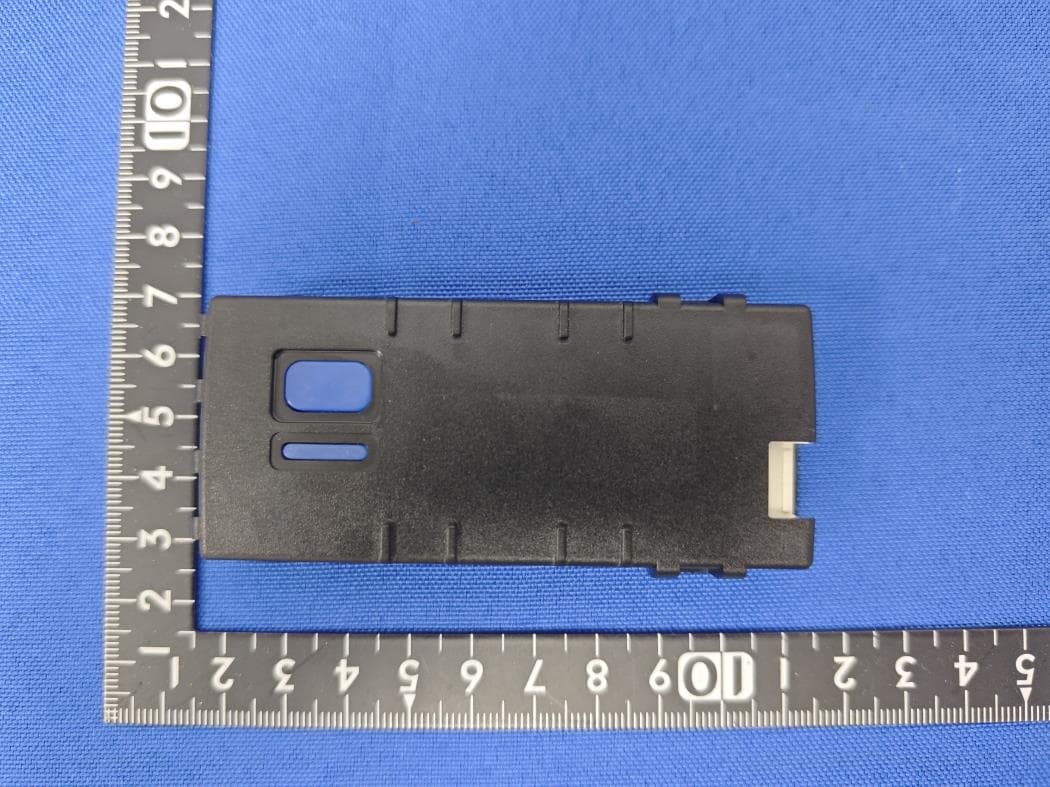
EZS1412VD
Jul 19, 2024KiB Ekey
Equipment Class
DTS - Digital Transmission System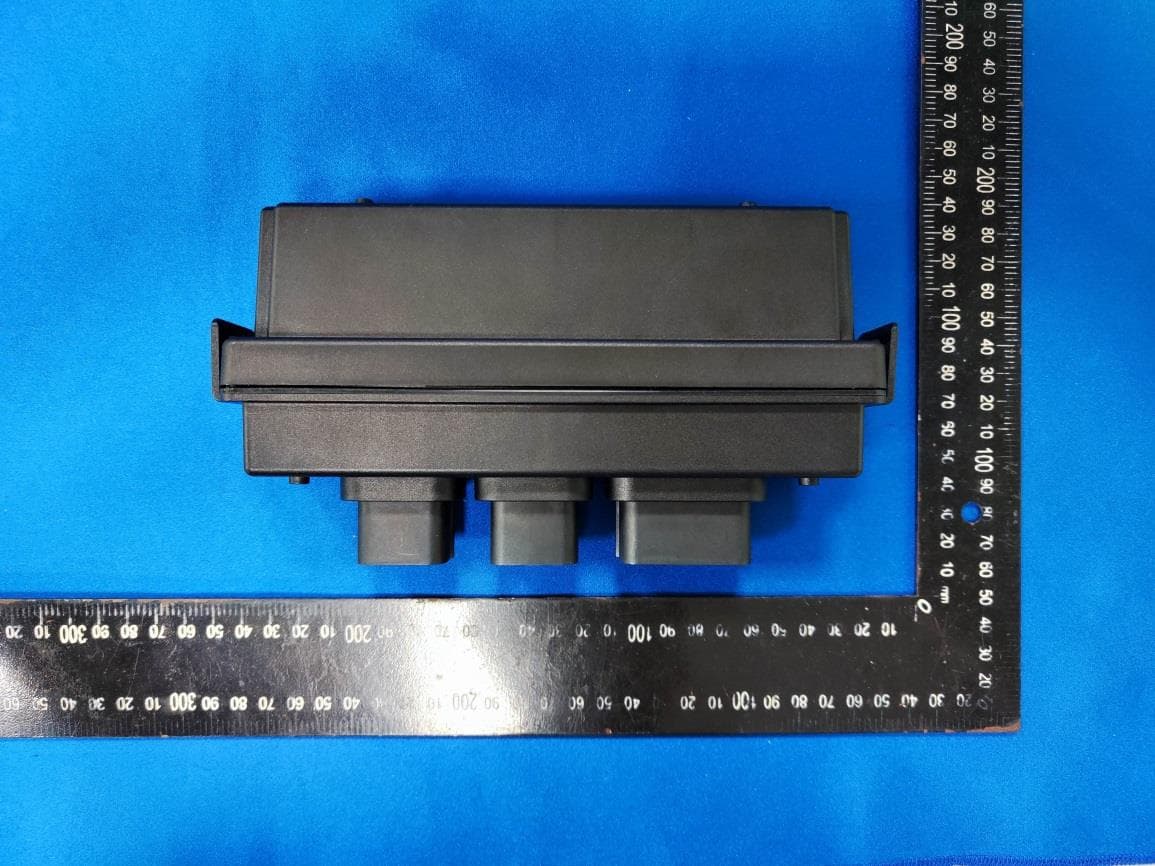
EZS8812
Dec 10, 20228812
Equipment Class
DTS - Digital Transmission System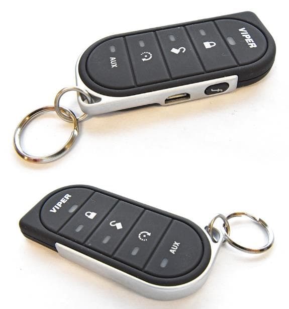
EZSG7857
Mar 22, 2021915MHz Remote Start Handheld Key fob
Equipment Class
DSS - Part 15 Spread Spectrum Transmitter