F8I-DSR0805BDigivance Software Defined Radio
ADC Telecommunications Inc
Click to zoom
Application Details
- Equipment Class
- TNB - Licensed Non-Broadcast Station Transmitter
- Date of Grant
- Nov 25, 2004
- Application Purpose
- Original Equipment
- Date of Application
- Sep 22, 2004
- Equipment Note
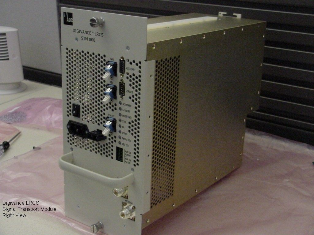
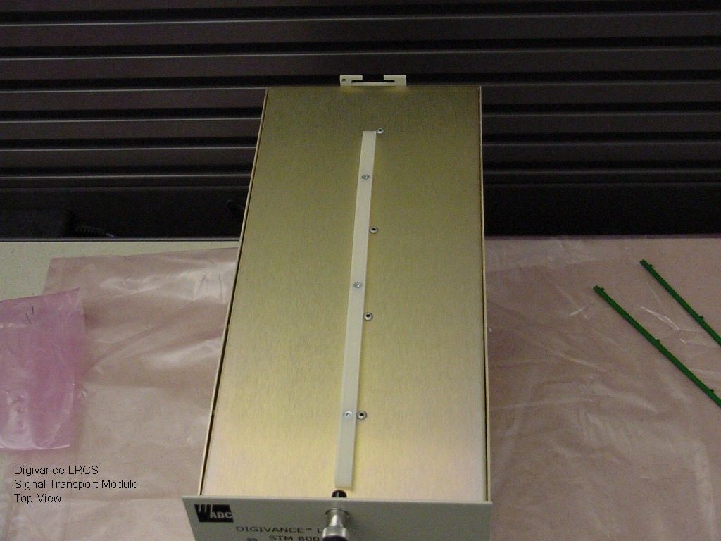
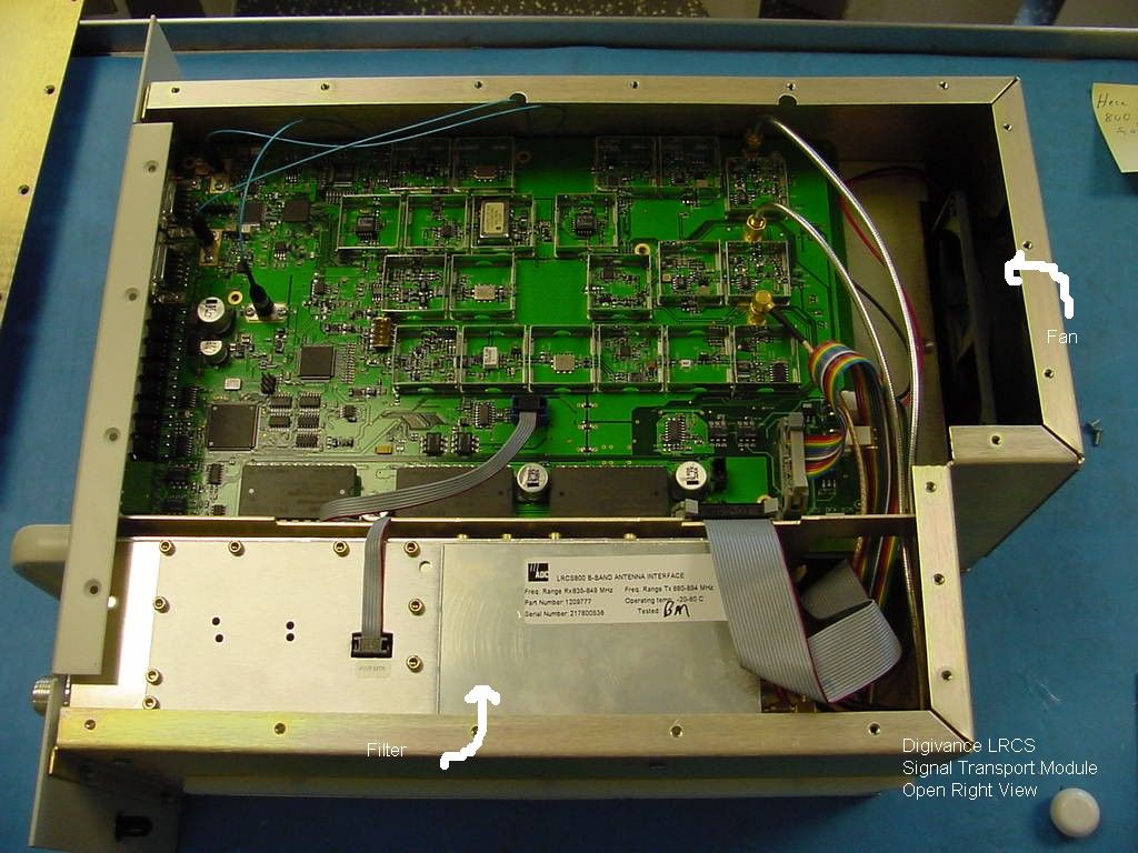
- Digivance Software Defined Radio
- Frequency Range
- 869.20000000 - 893.80000000
- Company
- ADC Telecommunications Inc
- Country
- United States
Documents & Files
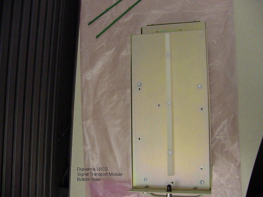
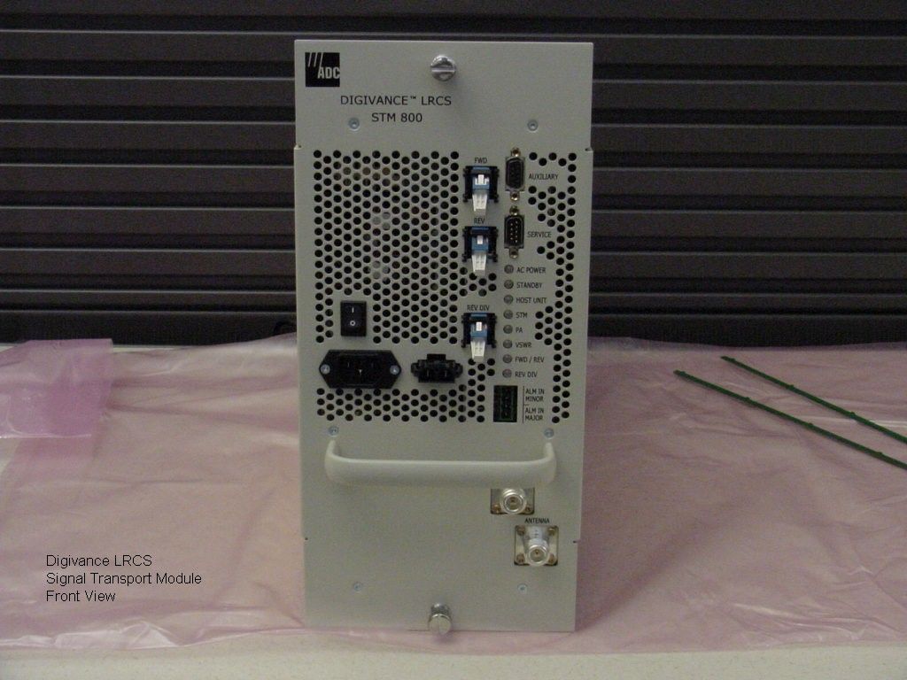
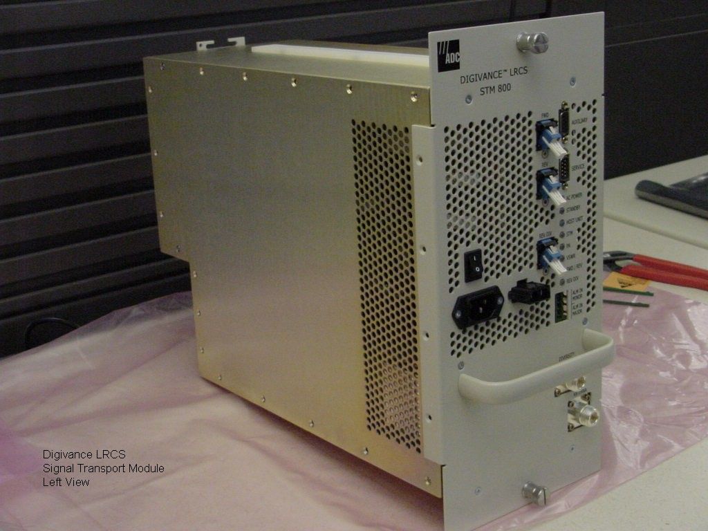
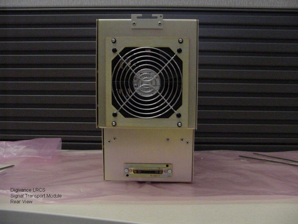
Document Text
Text extracted from the exhibit documents filed with the FCC. Open a document above to read the original.
Users Manual
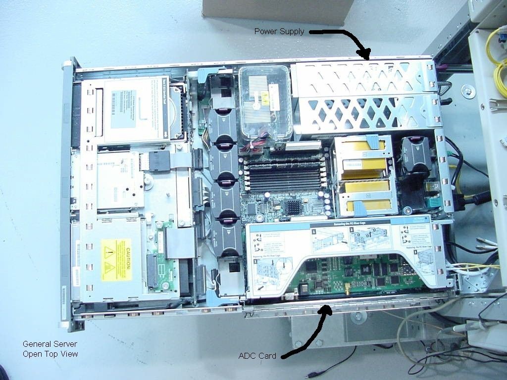
ADCP-75-163SDR • Issue 1 • September 2004 1278626 Rev SDRPage 1 © 2004, ADC Telecommunications, Inc. Digivance ® LRCS SDR PCIx Host Card Installation Instructions INTRODUCTION . . . . . . . . . . . . . . . . . . . . . . . . . . . . . . . . . . . . . . . . . . . . . . . . . . . . . . . . . . . . . . . . . . . . . . . . . . . . . 2 Revision History . . . . . . . . . . . . . . . . . . . . . . . . . . . . . . . . . . . . . . . . . . . . . . . . . . . . . . . . . . . . . . . . . . . . . . . . 2 List of Changes. . . . . . . . . . . . . . . . . . . . . . . . . . . . . . . . . . . . . . . . . . . . . . . . . . . . . . . . . . . . . . . . . . . . . . . . . 2 Trademark Information . . . . . . . . . . . . . . . . . . . . . . . . . . . . . . . . . . . . . . . . . . . . . . . . . . . . . . . . . . . . . . . . . . . 2 Admonishments . . . . . . . . . . . . . . . . . . . . . . . . . . . . . . . . . . . . . . . . . . . . . . . . . . . . . . . . . . . . . . . . . . . . . . . . 2 General Safety Precautions . . . . . . . . . . . . . . . . . . . . . . . . . . . . . . . . . . . . . . . . . . . . . . . . . . . . . . . . . . . . . . . . 2 FCC/IC Compliance Statement . . . . . . . . . . . . . . . . . . . . . . . . . . . . . . . . . . . . . . . . . . . . . . . . . . . . . . . . . . . . . . 3 Certification: UL/CSA Recognized . . . . . . . . . . . . . . . . . . . . . . . . . . . . . . . . . . . . . . . . . . . . . . . . . . . . . . . . . . . . 3 1DESCRIPTION . . . . . . . . . . . . . . . . . . . . . . . . . . . . . . . . . . . . . . . . . . . . . . . . . . . . . . . . . . . . . . . . . . . . . . . . . . 3 2SDR CARD INSTALLATION . . . . . . . . . . . . . . . . . . . . . . . . . . . . . . . . . . . . . . . . . . . . . . . . . . . . . . . . . . . . . . . . . 5 2.1Power Down the Server . . . . . . . . . . . . . . . . . . . . . . . . . . . . . . . . . . . . . . . . . . . . . . . . . . . . . . . . . . . . . 5 2.2Extend Server from the Rack . . . . . . . . . . . . . . . . . . . . . . . . . . . . . . . . . . . . . . . . . . . . . . . . . . . . . . . . . . 5 2.3Remove Access Panel . . . . . . . . . . . . . . . . . . . . . . . . . . . . . . . . . . . . . . . . . . . . . . . . . . . . . . . . . . . . . . 5 2.4Remove PCI Riser Cage . . . . . . . . . . . . . . . . . . . . . . . . . . . . . . . . . . . . . . . . . . . . . . . . . . . . . . . . . . . . . 6 2.5Remove Expansion Slot Cover . . . . . . . . . . . . . . . . . . . . . . . . . . . . . . . . . . . . . . . . . . . . . . . . . . . . . . . . . 6 2.6Installing a SDR PCIx Host Card . . . . . . . . . . . . . . . . . . . . . . . . . . . . . . . . . . . . . . . . . . . . . . . . . . . . . . . 6 2.7Install PCI Riser Cage . . . . . . . . . . . . . . . . . . . . . . . . . . . . . . . . . . . . . . . . . . . . . . . . . . . . . . . . . . . . . . 6 2.8Install Access Panel . . . . . . . . . . . . . . . . . . . . . . . . . . . . . . . . . . . . . . . . . . . . . . . . . . . . . . . . . . . . . . . 7 2.9Slide Server Into Rack . . . . . . . . . . . . . . . . . . . . . . . . . . . . . . . . . . . . . . . . . . . . . . . . . . . . . . . . . . . . . . 7 3SDR PCIX HOST CARD CABLING . . . . . . . . . . . . . . . . . . . . . . . . . . . . . . . . . . . . . . . . . . . . . . . . . . . . . . . . . . . . . 7 3.1Optical and Electrical Connections. . . . . . . . . . . . . . . . . . . . . . . . . . . . . . . . . . . . . . . . . . . . . . . . . . . . . . 7 3.2Coax Cabling . . . . . . . . . . . . . . . . . . . . . . . . . . . . . . . . . . . . . . . . . . . . . . . . . . . . . . . . . . . . . . . . . . . . 7 3.3Optical Cabling . . . . . . . . . . . . . . . . . . . . . . . . . . . . . . . . . . . . . . . . . . . . . . . . . . . . . . . . . . . . . . . . . . . 8 3.4Modular Optical Transceiver Installation. . . . . . . . . . . . . . . . . . . . . . . . . . . . . . . . . . . . . . . . . . . . . . . . . 11 4POWERING UP THE SERVER . . . . . . . . . . . . . . . . . . . . . . . . . . . . . . . . . . . . . . . . . . . . . . . . . . . . . . . . . . . . . . . 13 5GAIN CONFIGURATION PARAMETERS . . . . . . . . . . . . . . . . . . . . . . . . . . . . . . . . . . . . . . . . . . . . . . . . . . . . . . . . 13 5.1Gain (Attenuation) . . . . . . . . . . . . . . . . . . . . . . . . . . . . . . . . . . . . . . . . . . . . . . . . . . . . . . . . . . . . . . . . 13 5.2Wide-band Gain (Attenuation) . . . . . . . . . . . . . . . . . . . . . . . . . . . . . . . . . . . . . . . . . . . . . . . . . . . . . . . . 13 6OPERATION . . . . . . . . . . . . . . . . . . . . . . . . . . . . . . . . . . . . . . . . . . . . . . . . . . . . . . . . . . . . . . . . . . . . . . . . . . 13 6.1Alarm LED . . . . . . . . . . . . . . . . . . . . . . . . . . . . . . . . . . . . . . . . . . . . . . . . . . . . . . . . . . . . . . . . . . . . . 13 7SPECIFICATIONS. . . . . . . . . . . . . . . . . . . . . . . . . . . . . . . . . . . . . . . . . . . . . . . . . . . . . . . . . . . . . . . . . . . . . . . 14 8CUSTOMER INFORMATION AND ASSISTANCE . . . . . . . . . . . . . . . . . . . . . . . . . . . . . . . . . . . . . . . . . . . . . . . . . . . 17 _________________________________________________________________________________________________________ ContentPage ADCP-75-163SDR • Issue 1 • September 2004 Page 2 © 2004, ADC Telecommunications, Inc. INTRODUCTION These instructions provide installation information for installing a Software Defined Radio (SDR) PCIx host card in a dedicated server. Revision History List of Changes Trademark Information ADC and Digivance are registered trademarks of ADC Telecommunications, Inc. Admonishments Important safety admonishments are used throughout this manual to warn of possible hazards to persons or equipment. An admonishment identifies a possible hazard and then explains what may happen if the hazard is not avoided. The admonishments — in the form of Dangers, Warnings, and Cautions — must be followed at all times. These warnings are flagged by use of the triangular alert icon (seen below), and are listed in descend…
Text truncated - open the document above for the full version.
Cover Letter(s)
6185 Phyllis Drive, Unit D Cypress, CA 90630 Tel: (714) 230-8333 Fax: (714) 230-8341 Web: www.bravotechinc.com 29 September 2004 Federal Communications Commission Equipment Approval Services P.O. Box 358315 Pittsburgh, PA 15251-5315 Re: Request of Confidentiality Pursuant to Section 0.457(d)(ii) and 0.459 of the Commission’s Rules, Bravo Tech hereby requests confidential treatment of information accompanying as outlined below: • Power Amplifier Schematics, model LPA0800-050-SC01 The above materials contain trade secrets and proprietary information not customarily released to the public. The public disclosure of these matters might be harmful to Bravo Tech and provide unjustified benefits to its competitors. Bravo Tech requests that the schematics are held confidential not only from the public, but also the applicant (Vanu, Inc.) Sincerely Hai Tran Project Manager Bravo Tech Inc. Telephone Number (714) 230-8330 x 122 Fax Number (714) 230-8341 Email Address: [email protected]
ID Label/Location Info
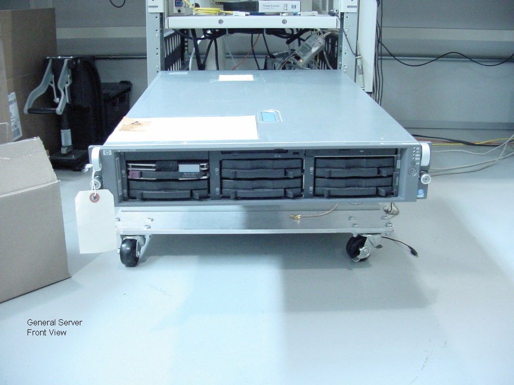
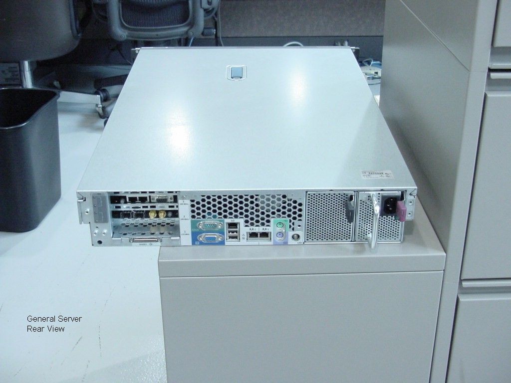
Instructions for Viewing System FCC ID Label 1. Connect the RS-232 port on a laptop or other computer to the RS-232 serial console port of the BTS using a null modem cable. On the HP Proliant servers, the serial console port is located in the rear center of the server surrounded by a green label. The two figures below show the null modem cable connected to the serial console port on the HP Proliant server. Figure 1: Null modem cable connected to the serial console port of the HP Proliant server Figure 2: Close-up of a null modem cable connected to the serial console port of the HP Proliant server. 2. Turn on power to the BTS Server if it was turned off. Wait at least one minute for the server to finish booting. 3. Run a serial communications program such as HyperTerminal, bundled for free in Microsoft Windows systems, on the client laptop. Select to use the RS-232 port for communications (in HyperTerminal under Windows, this corresponds to selecting COM3 or another COM port in the initialization dialog box). Set the RS- 232 port to 115200 bits per second, 8 data bits, no parity bits, 1 stop bit, and hardware flow control. 4. Press the Enter key in the active HyperTerminal session. The BTS will respond by printing out identifying information and prompting for a login. A screen shot of an example HyperTerminal session is shown below. Figure 3: Screenshot of HyperTerminal view of system FCC ID
Internal Photos
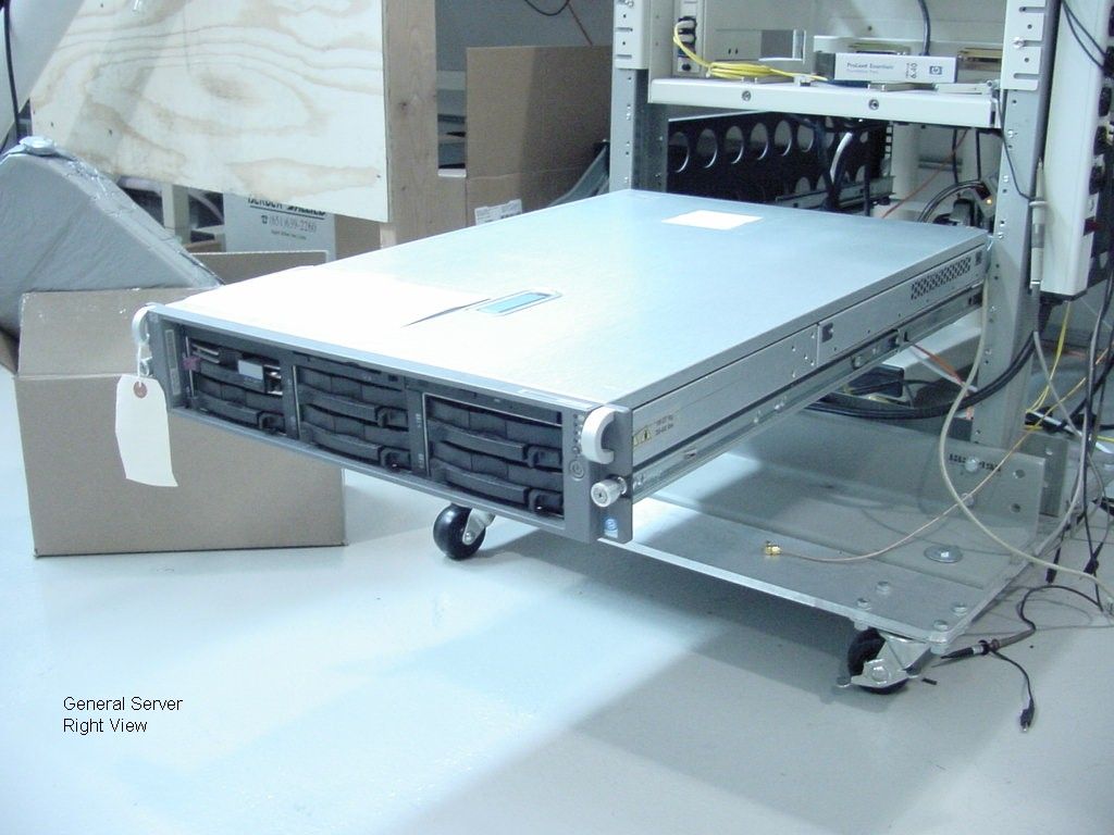
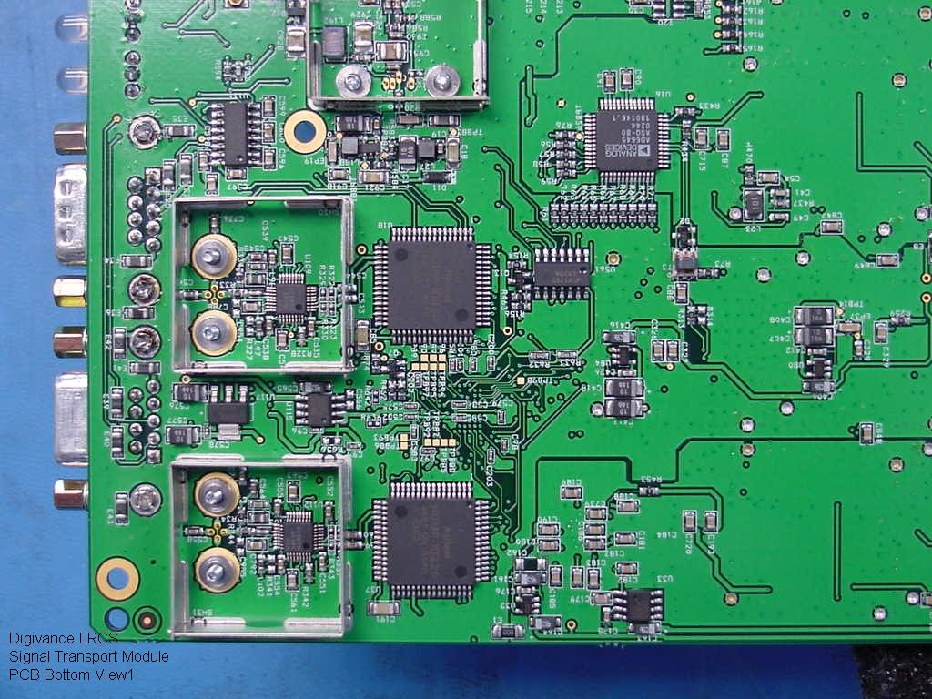
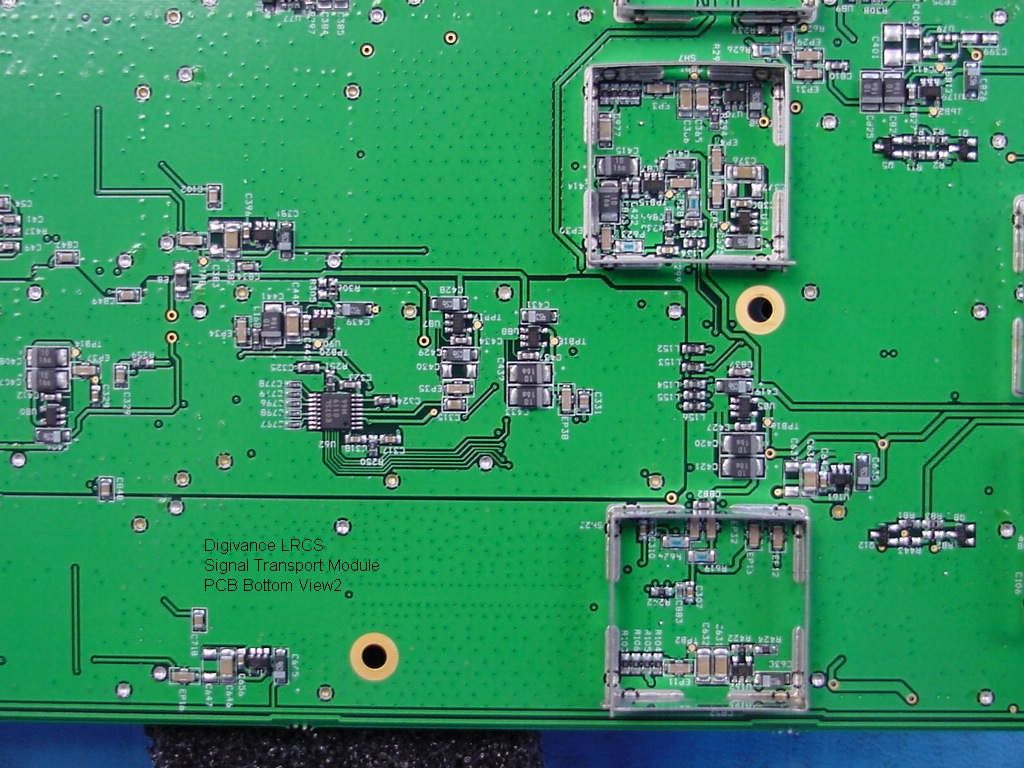
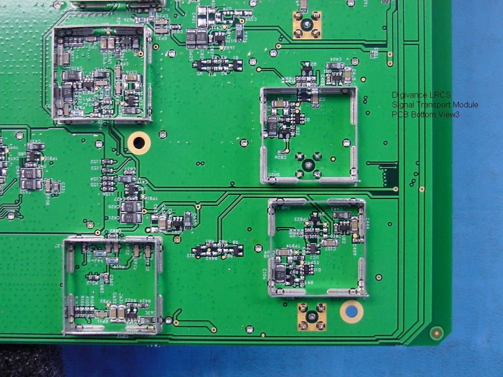
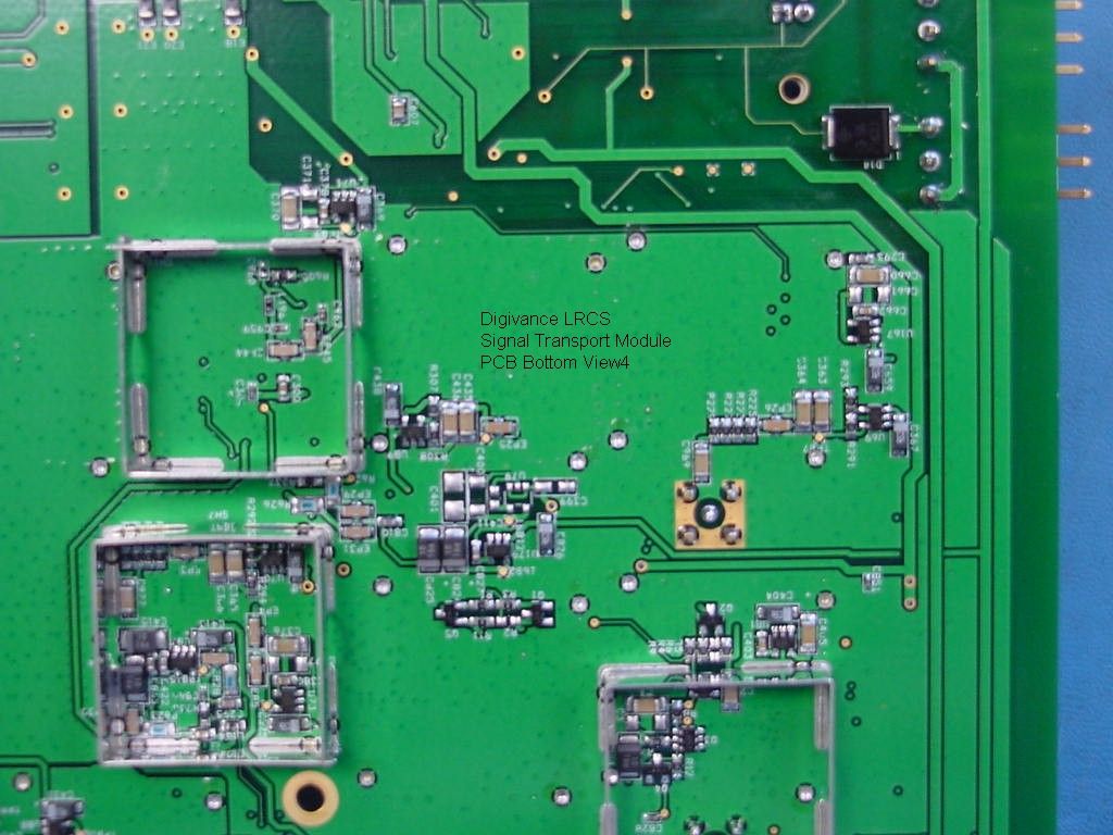
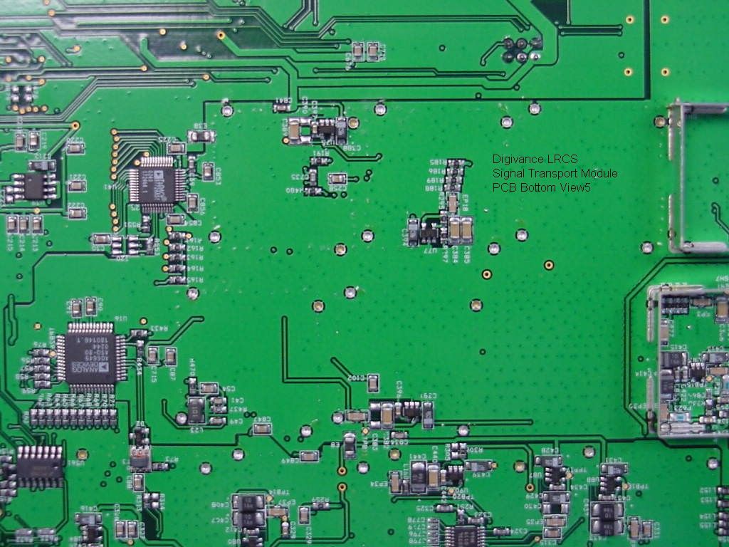
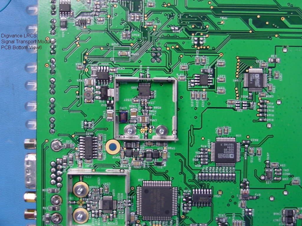
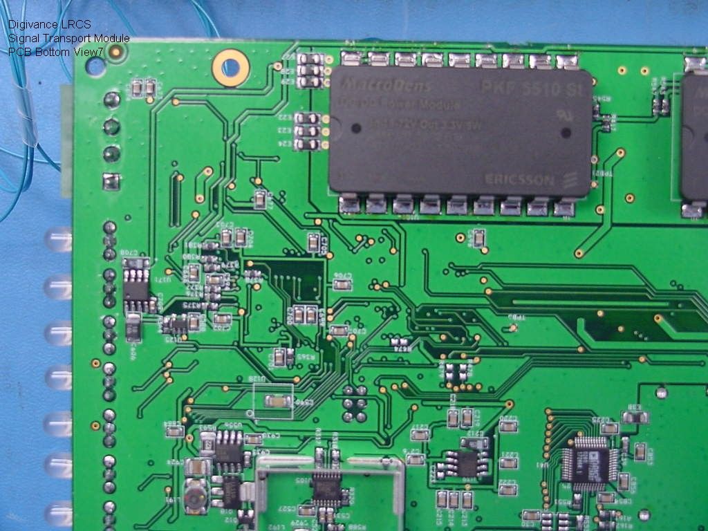
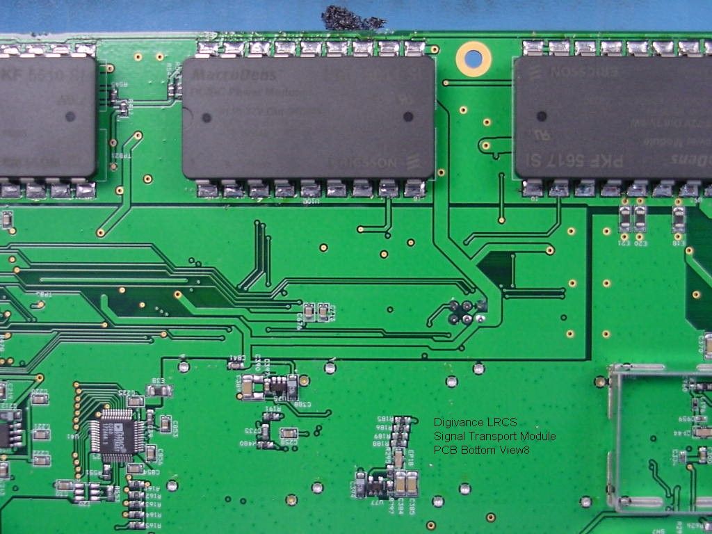
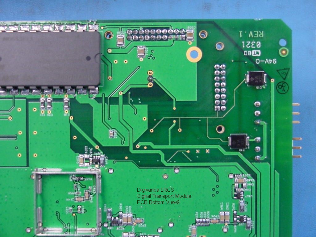
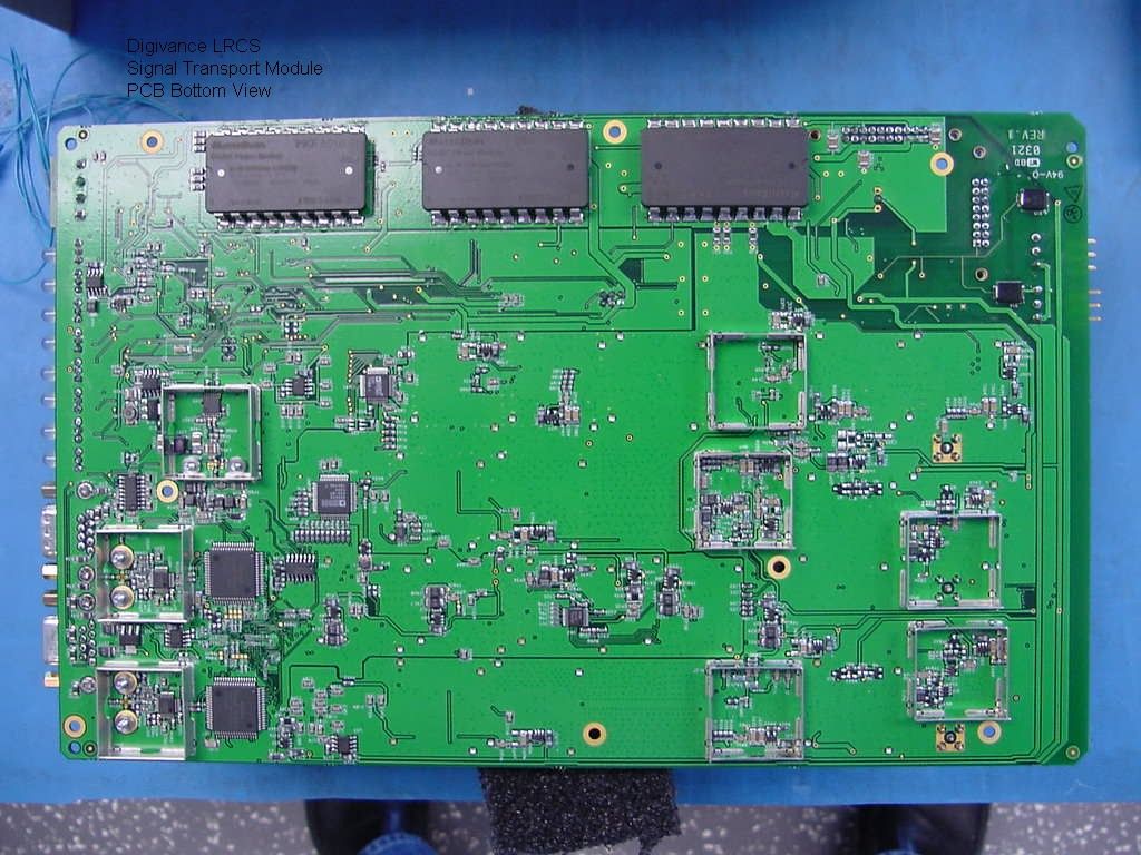
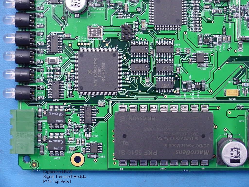
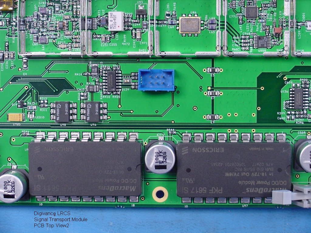
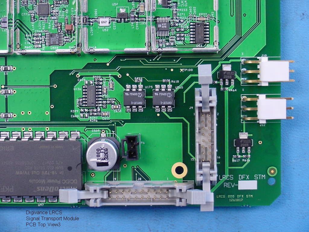
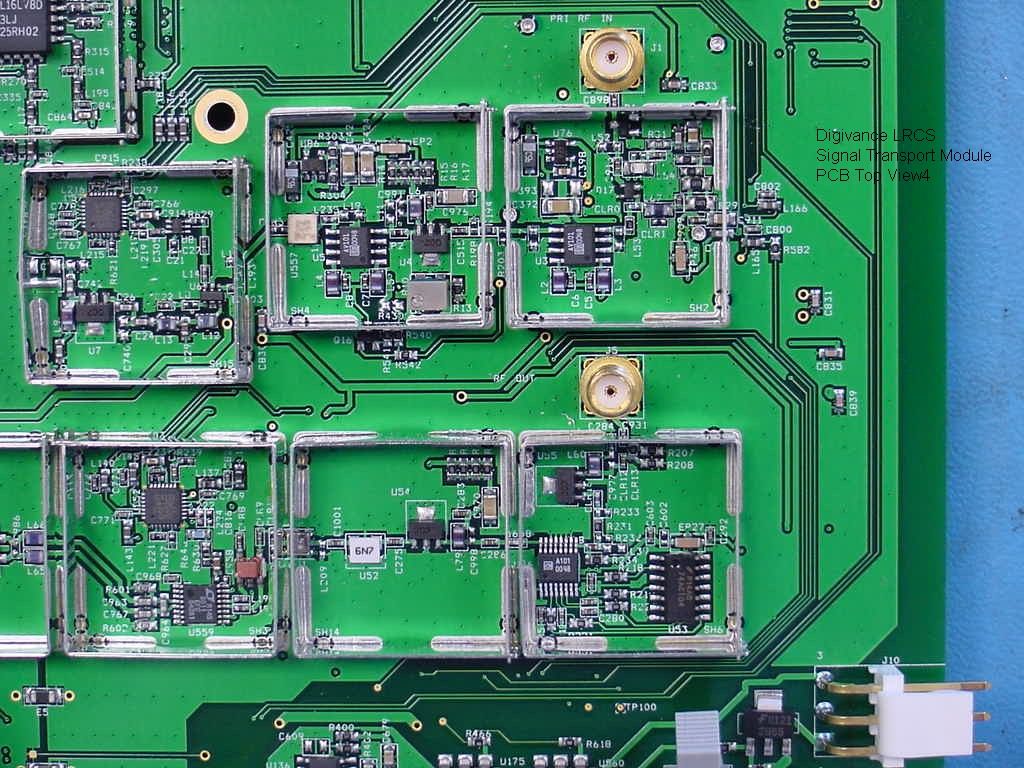
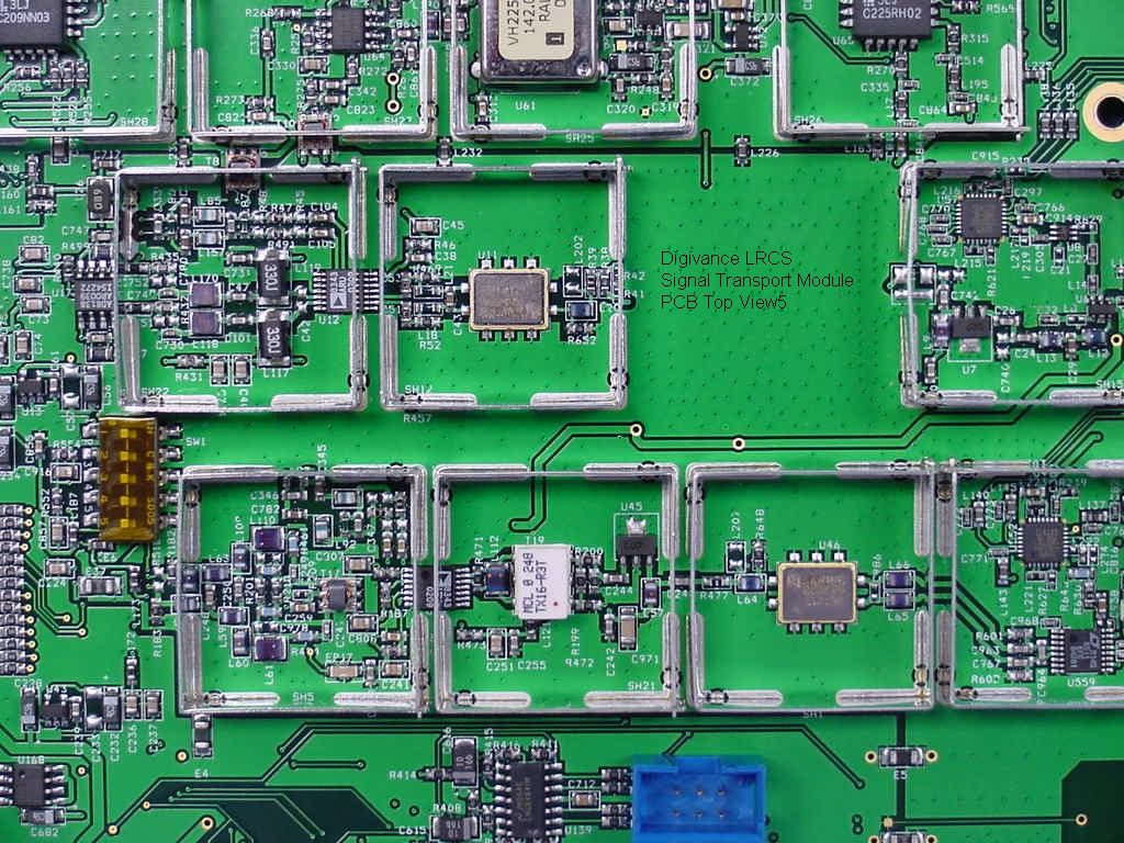
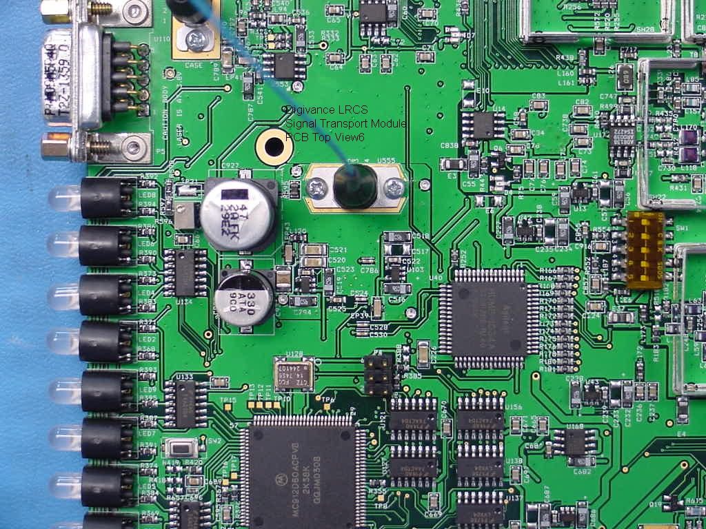
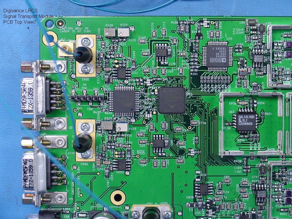
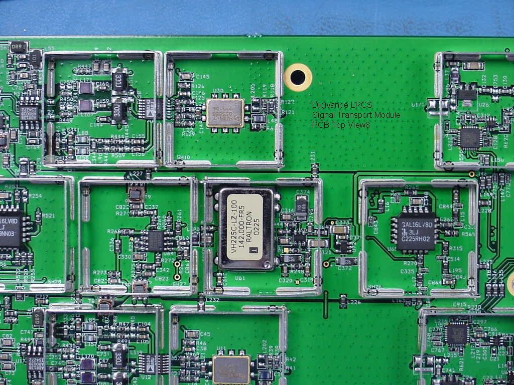
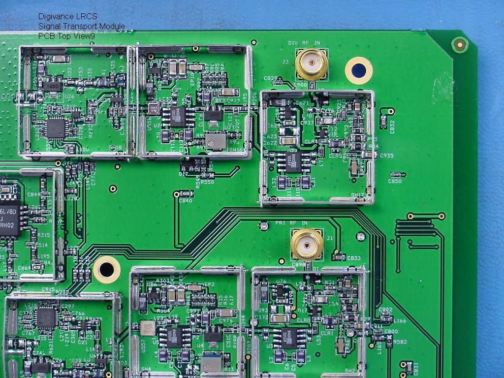
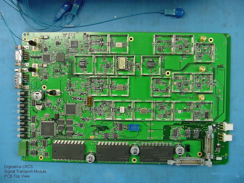
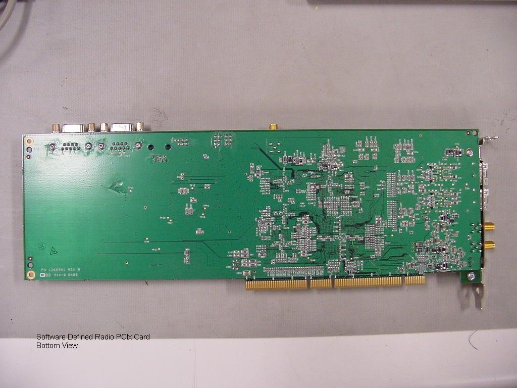
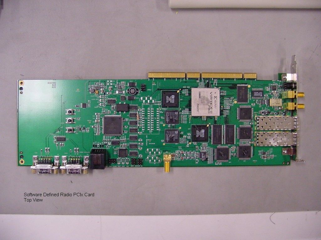
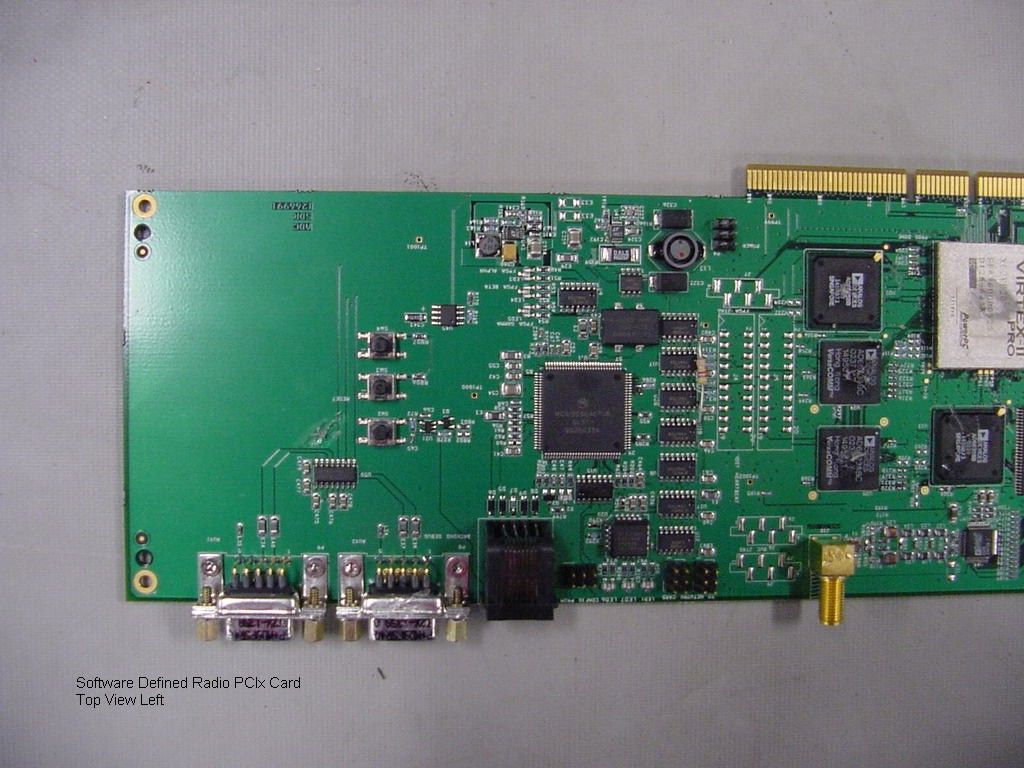
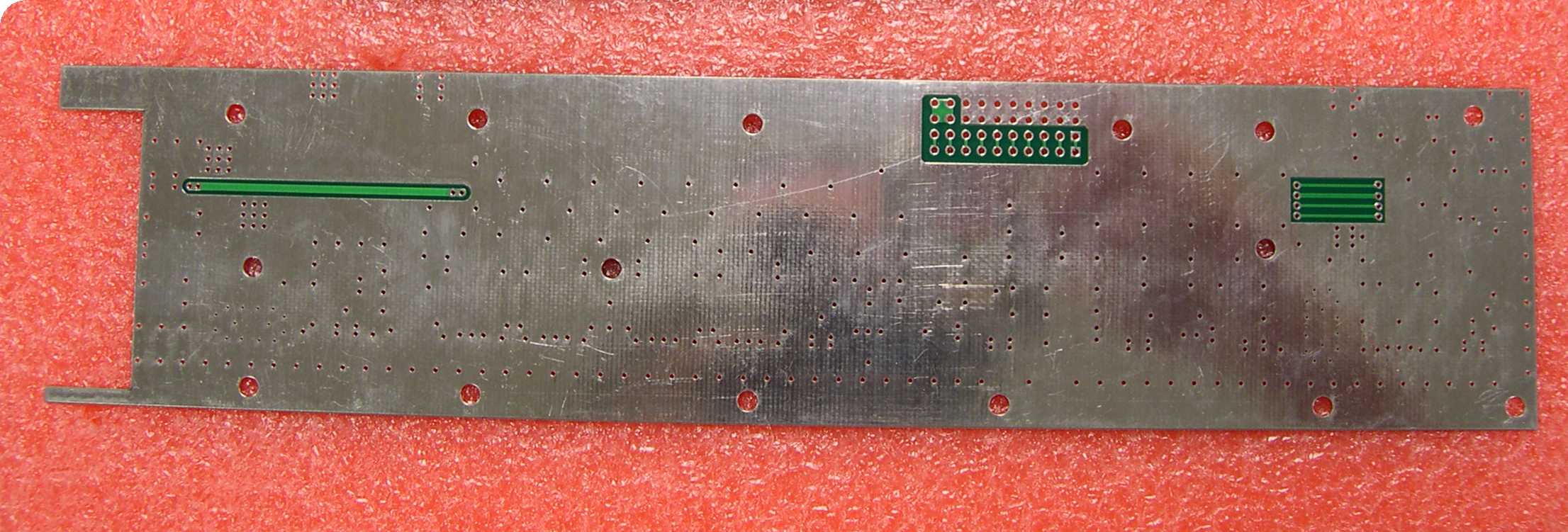
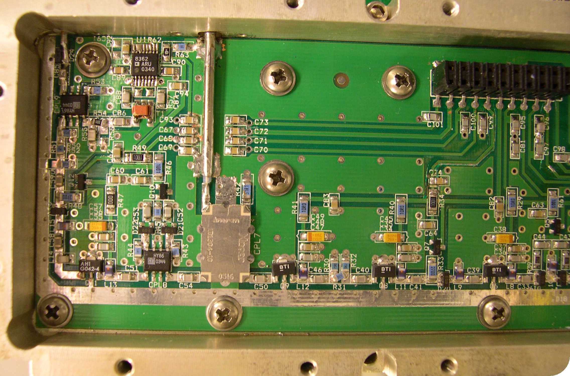
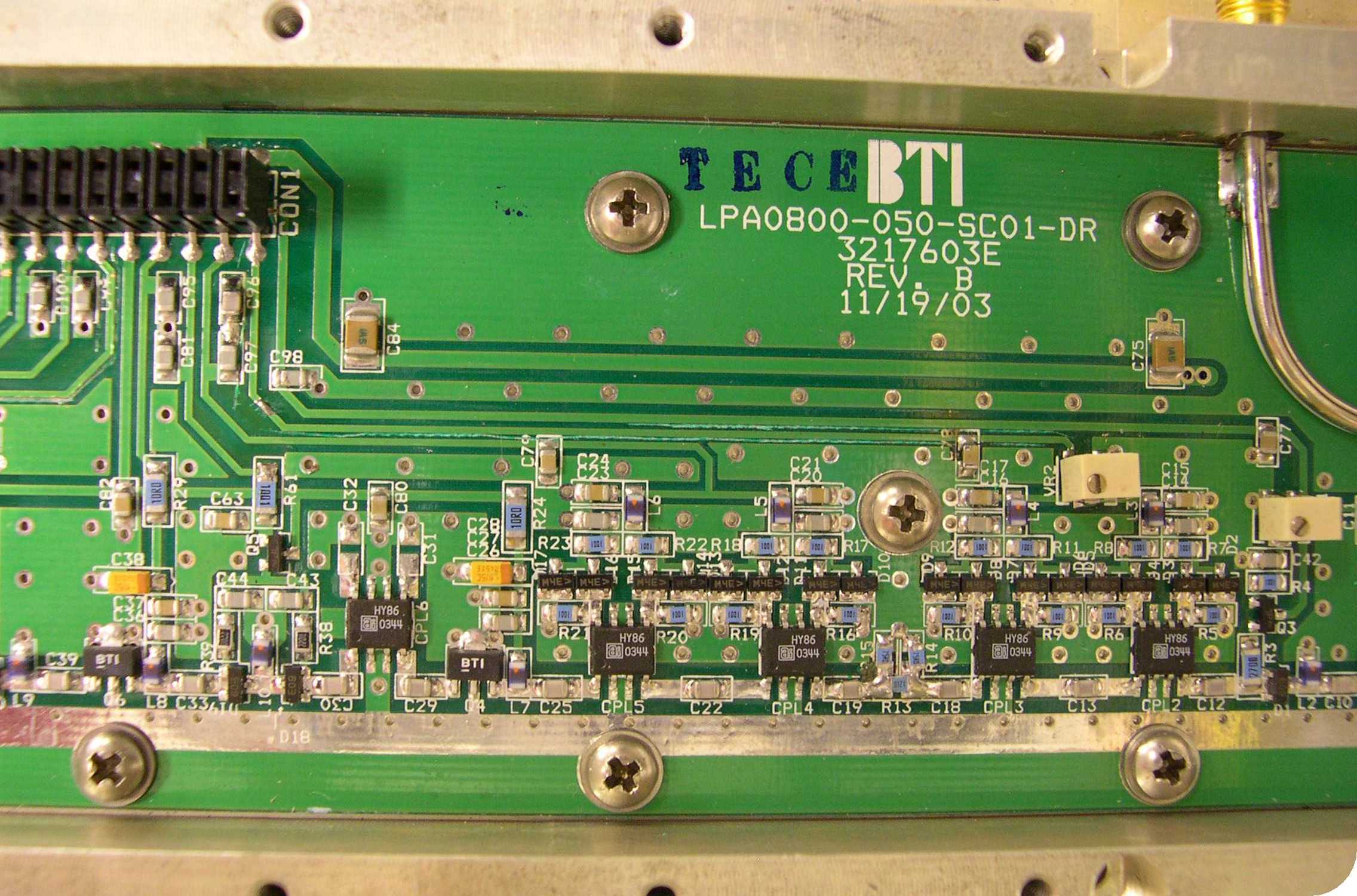
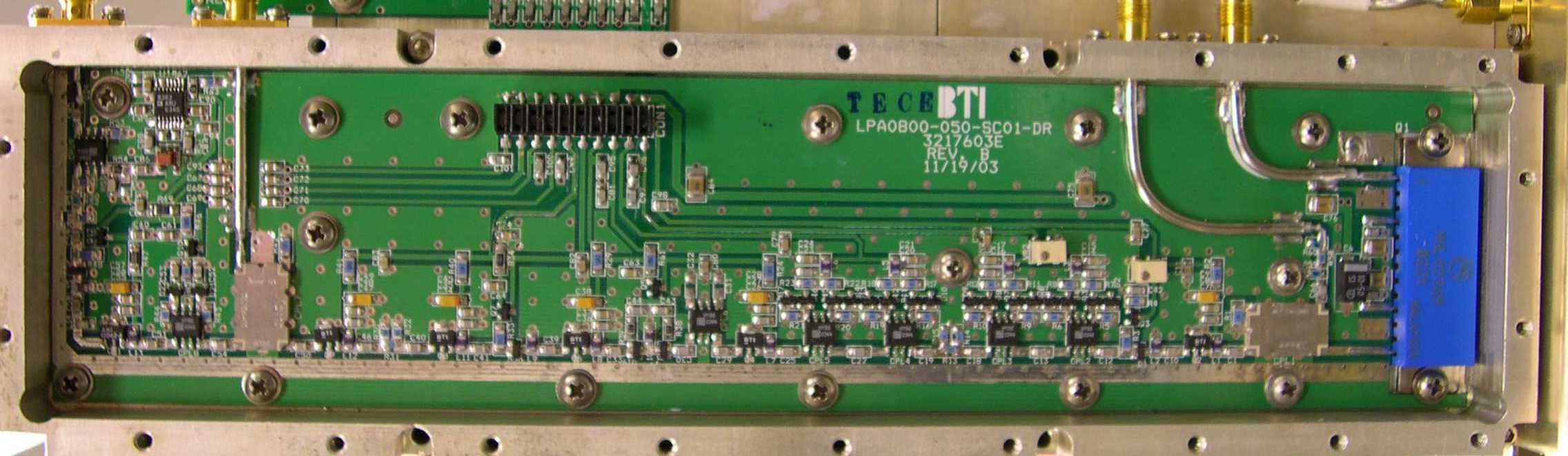
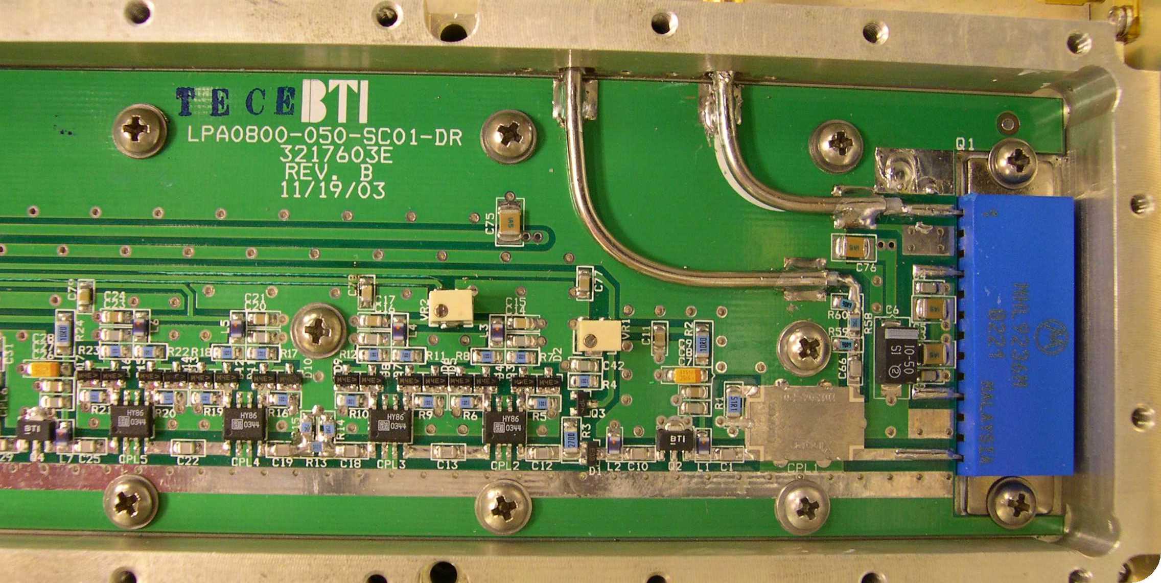
Front and back pictures of each PCB for FCC purpose. There are 14 PCB’s used in amplifier. 1. 3217603E - driver board 2. 3217604E - pre-error 3. 3217605E - error amplifier 4. 3217606E - sample coupler 5. 3217607E - delay 6. 3217608E - output coupler 7. 3217610E - detector 8. 3217612E - main amp 9. 3219609E - pilot tone 10. 3219611E - main amplifier mother board 11. 3219612E - main mother board 12. 3219613E - LCD 13. 3219617E - error amplifier mother board 14. 3227602E - control board
Test Report
PRODUCT SERVICE TEST RESULT SUMMARY FCC PART 22 SUBPART H MANUFACTURER 2 - NAME ADC Inc. MANUFACTURER'S ADDRESS PO Box 1101 Minneapolis MN 55440 NAME OF EQUIPMENT Digivance Wide Band Digital Radio 800 MHz 50-Watt System MODEL NUMBER(S) DGVS-112710SYS DGVS-122710SYS MANUFACTURER 1 - NAME Vanu, Inc. MANUFACTURER'S ADDRESS One Porter Square, Suite 18 Cambridge MA 02140 NAME OF EQUIPMENT Vanu Software Radio Base Station MODEL NUMBER(S) RAN-1.0 TEST REPORT NUMBER WC402208.4 TEST DATE 07 May 2004 According to testing performed at TÜV Product Service Inc, the above-mentioned unit is in compliance with the electromagnetic compatibility requirements defined in FCC Part 22 Subpart H. It is the manufacturer's responsibility to assure that additional production units of this model are manufactured with identical electrical and mechanical characteristics. Any modifications necessary for compliance made during testing on the above mentioned date(s) must be implemented in all production units for compliance to be maintained. TÜV Product Service Inc, as an independent testing laboratory, declares that the equipment tested as specified above conforms to the requirements of FCC Part 22 Subpart H. Date: 23 September 2004 Location: Taylors Falls MN J. C. Sausen J. T. Schneider USA Test Technician Chief Engineer Not Transferable File No. WC402208.4, Page 1 of 136 TÜV PRODUCT SERVICE INC 19333 Wild Mountain Road Taylors Falls MN 55084-1758 Tel: 651 638 0297 Fax: 651 638 0298Rev.No 1.0 PRODUCT SERVICE EMC EMISSION - T E S T R E P O R T Test Report File No. : WC402208.4 Date of issue: 23 September 2004 MANUFACTURER 2 - NAME ADC Inc. MANUFACTURER'S ADDRESS PO Box 1101 Minneapolis MN 55440 NAME OF EQUIPMENT Digivance Wide Band Digital Radio 800 MHz 50-Watt System MODEL NUMBER(S) DGVS-112710SYS DGVS-122710SYS MANUFACTURER 1 - NAME Vanu, Inc. MANUFACTURER'S ADDRESS One Porter Square, Suite 18 Cambridge MA 02140 NAME OF EQUIPMENT Vanu Software Radio Base Station MODEL NUMBER(S) RAN-1.0 TEST REPORT NUMBER WC402208.4 TEST DATE 07 May 2004 Test Result : Positive Negative Test Project Number : Reference(s) WC402208.4 Total pages including Appendices 144 TÜV Product Service Inc is a subcontractor to TÜV Product Service, GmbH according to the principles outlined in ISO/IEC Guide 25 and EN 45001. TÜV Product Service Inc reports apply only to the specific samples tested under stated test conditions. It is the manufacturer's responsibility to assure that additional production units of this model are manufactured with identical electrical and mechanical components. TÜV Product Service Inc shall have no liability for any deductions, inferences or generalizations drawn by the client or others from TÜV Product Service Inc issued reports. This report is the confidential property of the client. As a mutual protection to our clients, the public and ourselves, extracts from the test report shall not be reproduced except in full without our written approval. This report shall not be used by the client to claim product endorsement by NVLAP or any agency of the US government. TÜV Product Service Inc and its professional staff hold government and professional organization certifications and are members of AAMI, ACIL, AEA, ANSI, IEEE, NVLAP, and VCCI File No. WC402208.4, Page 2 of 136 TÜV PRODUCT SERVICE INC 19333 Wild Mountain Road Taylors Falls MN 55084-1758 Tel: 651 638 0297 Fax: 651 638 0298Rev.No 1.0 PRODUCT SERVICE D I R E C T O R Y - EMISSIONS Page(s) A) Documentation Test report 1 – 136 Directory 2 Test Regulations 3 B) Test data 22.355 Frequency tolerance 5 - 7 22.913 Effective Radiated Power Limit 8 - 9 22.915 Modulation requirements 10 22.917 Emission Limitations for cellular 10 - 112 2.1053 Case radiation 113 - 125 EUT Operating Mode and Configuration Information 126 Deviations, General Remarks and Summary 127 Test Equipment List 128 Test Setup Diagrams and Photo(s) 129 - 136 C) Product Information Product Information Form A1 – A8 File No. WC402208.4, Page 3 of 136 TÜV PRODUCT SERVICE INC 19333 Wild Mountain Road Taylors Falls MN 55084-1758 Tel: 651 638 0297 Fax: 651 638 0298Rev.No 1.0 PRODUCT SERVICE EMISSIONS TEST REGULATIONS : The emissions tests were performed according to following regulations: -------------------------------------------------------------------------------- - EN 50081-1 / 1991 - EN 55011 / 1991 - Group 1 - Group 2 - Class A - Class B - EN 55013 / 1990 - EN 55014 / 1987 - Household appliances and similar - Portable tools - Semiconductor devices - EN 55014 / A2:1990 - EN 55014 / 1993 - Household appliances and similar - Portable tools - Semiconductor devices - EN 55015 / 1987 - EN 55015 / A1:1990 - EN 55015 / 1993 - EN 55022 / 1987 - Class A - Class B - FCC Part 22 Subpart H - BS - VCCI - Class A - Class B - FCC - Class A - Class B - AS 3548 (1992) - Class A - Class B - CISPR 11 (1990) - Group 1 - Group 2 - Class A - Class B - CISPR 22 (1993) - Class A - Class B File No. WC402208.4, Page 4 of 136 TÜV PRODUCT SERVICE INC 19333 Wild Mountain Road Taylors Falls MN 55084-1758 Tel: 651 638 0297 Fax: 651 638 0298Rev.No 1.0 PRODUCT SERVICE Environmental conditions in the lab: Actual Temperature : 23 °C Relative Humidity : 28 % Atmospheric pressure : 98.0 kPa Power supply system : 60 Hz - 115 V - 1-phase Sign Explanations: - not applicable - applicable File No. WC402208.4, Page 5 of 136 TÜV PRODUCT SERVICE INC 19333 Wild Mountain Road Taylors Falls MN 55084-1758 Tel: 651 638 0297 Fax: 651 638 0298Rev.No 1.0 PRODUCT SERVICE 22.355 Frequency tolerance The Frequency Tolerance measurements were performed at the following test location: - ADC facility The EUT Server is specified for indoor use only with temperature range of +10 to +35º C and was tested within its range. The EUT STM and LPA are specified with a temperature range of -30 to +50º C and were tested within their range. The remote units are placed in the temp chamber a…
Text truncated - open the document above for the full version.
Test Report
Software Test 10 for Digivance 800 MHz 50-Watt SDR System Model Numbers DGVS-112710SYS and DGVS-122710SYS The out of band emissions were measured directly from the EUT antenna output with a spectrum analyzer from 30 MHz to the 10 th harmonic of the highest carrier frequency. The Software Test 10 simulates the GSM signal created from a sequence of all ones. Results: Pass (see plots) File No. WC402208.4, Page 92 of 136 File No. WC402208.4, Page 93 of 136 File No. WC402208.4, Page 94 of 136 File No. WC402208.4, Page 95 of 136 File No. WC402208.4, Page 96 of 136 File No. WC402208.4, Page 97 of 136 File No. WC402208.4, Page 98 of 136 Software Test 11 for Digivance 800 MHz 50-Watt SDR System Model Numbers DGVS-112710SYS and DGVS-122710SYS The out of band emissions were measured directly from the EUT antenna output with a spectrum analyzer from 30 MHz to the 10 th harmonic of the highest carrier frequency. The Software Test 11 simulates the GSM signal created from a repeated sequence with 1 timeslot of valid control channel data and the remaining 7 timeslots filled with dummy bursts. Results: Pass (see plots) File No. WC402208.4, Page 99 of 136 File No. WC402208.4, Page 100 of 136 File No. WC402208.4, Page 101 of 136 File No. WC402208.4, Page 102 of 136 File No. WC402208.4, Page 103 of 136 File No. WC402208.4, Page 104 of 136 File No. WC402208.4, Page 105 of 136 File No. WC402208.4, Page 106 of 136 File No. WC402208.4, Page 107 of 136 File No. WC402208.4, Page 108 of 136 File No. WC402208.4, Page 109 of 136 Occupied Bandwidth Modulation Test for ADC Inc. Digivance 800 MHz 50-Watt WBDR System Model Numbers DGVS-112710SYS and DGVS-122710SYS An output Occupied Bandwidth test was done with modulation type GSM. The purpose was to determine the amount of distortion added to this modulation scheme by the EUT. The following plots show output signals. Results: Pass (see plots) File No. WC402208.4, Page 110 of 136 File No. WC402208.4, Page 111 of 136 File No. WC402208.4, Page 112 of 136 File No. WC402208.4, Page 113 of 136 TÜV PRODUCT SERVICE INC 19333 Wild Mountain Road Taylors Falls MN 55084-1758 Tel: 651 638 0297 Fax: 651 638 0298Rev.No 1.0 PRODUCT SERVICE A radiated emission scan was also made, at TUV America’s Wild River Lab Large Test Site, with the EUT’s antenna replaced with a termination to demonstrate case radiation compliance to the –13 dBm requirement at the 3 carrier frequencies. Radiated emissions from the EUT are measured in the frequency range of 30 to 9000 MHz using a spectrum analyzer and appropriate broadband linearly polarized antennas. Measurements between 30 MHz and 1000 MHz are made with 120 kHz/6 dB bandwidth and quasi-peak detection and measurements above 1000 MHz are made with a 1 MHz/6 dB bandwidth and peak detection. Table top equipment is placed on a 1.0 X 1.5 meter non-conducting table 80 centimeters above the ground plane. Floor standing equipment is placed directly on the turntable/ground plane. Interface cables that are closer than 40 centimeters to the ground plane are bundled in the center in a serpentine fashion so they are at least 40 centimeters from the ground plane. Cables to simulators/testers (if used in this test) are routed through the center of the table and to a screen room located outside the test area. The antenna is positioned 10 meters horizontally from the EUT. To locate maximum emissions from the test sample the antenna is varied in height from 1 to 4 meters, measurement scans are made with both horizontal and vertical antenna polarizations and the EUT are rotated 360 degrees. The field strength levels were measured per ANSI C63.4. The EUT is then replaced with a tuned dipole antenna (below 1 GHz) or horn antenna (above 1 GHz). The substitute antenna was placed in the same polarization as the test antenna. A signal generator was used to generate a signal level that matched the highest level measured from the EUT. The signal generator level minus the cable loss from the signal generator to the substitute antenna plus the substitute antenna gain equals the spurious power level. 2 case radiation emission scans were performed. The highest emission frequency from the two scans is listed below. Run 1 Frequency MHz dBuV/m(from EUT) Substitution power level - dBm 910.44 67.5 -32.49 Case Radiation data is on the following pages: RADIATED EMISSIONS Test Report #: 2208 Run 1 Test Area: LTS EUT Model #: DGVS-112710SYS Date: 5/7/04 EUT Serial #: EUT Power: 60 Hz / 110 VAC Temperature: 23.0 °C Test Method: FCC Part 22 Air Pressure: 98.0 kPa Customer: ADC Mark Miska Rel. Humidity: 35.0 % EUT Description: Digivance 800 MHz 50 Watt SDRS Notes: Data File Name: 2208convertedtodbm.dat Page: 1 of 6 Tested by: J. C. Sausen Printed Signature Reviewed by: T. K. Swanson Printed Signature List of measurements for run #: 1 FREQ LEVEL (dBuV) CABLE / ANT / PREAMP / ATTEN (dB) FINAL (dBm) POL / HGT / AZ (m)(DEG) DELTA1 DELTA (dBm) part 22 case radiation qp Channel 128 (869.2 MHz) 1.0 GHz 38.9 Pk 2.74 / 26.4 / 38.2 / -100.5 -70.66 H / 1.00 / 0 n/a -57.66* 1.065 GHz 43.15 Pk 2.83 / 26.44 / 39.29 / -100.5 -67.36 H / 1.00 / 0 n/a -54.36* 1.136 GHz 40.5 Pk 2.93 / 26.48 / 39.9 / -100.5 -70.49 H / 1.00 / 0 n/a -57.49* 1.207 GHz 40.6 Pk 3.01 / 26.52 / 40.28 / -100.5 -70.64 H / 1.00 / 0 n/a -57.64* 1.278 GHz 51.3 Pk 3.1 / 26.57 / 40.56 / -100.5 -60.09 H / 1.00 / 0 n/a -47.09* 1.28 GHz 44.0 Pk 3.1 / 26.57 / 40.57 / -100.5 -67.4 H / 1.00 / 0 n/a -54.4* 1.491 GHz 44.8 Pk 3.42 / 26.69 / 41.53 / -100.5 -67.11 H / 1.00 / 0 n/a -54.11* 1.558 GHz 40.45 Pk 3.48 / 27.04 / 41.72 / -100.5 -71.25 H / 1.00 / 0 n/a -58.25* 1.633 GHz 42.9 Pk 3.55 / 27.47 / 41.92 / -100.5 -68.5 H / 1.00 / 0 n/a -55.5* 1.704 GHz 44.0 Pk 3.62 / 27.88 / 42.1 / -100.5 -67.1 H / 1.00 / 0 n/a -54.1* 1.738 GHz 59.05 Pk 3.68 / 28.08 / 42.19 / -100.5 -51.88 H / 1.00 / 0 n/a -38.88* 1.775 GHz 42.5 Pk 3.74 / 28.3 / 42.31 / -100.5 -68.27 H / 1.00 / 0 n/a -55.27* 1.78 GHz 41.7 Pk 3.75 / 28.32 / 42.32 / -100.5 -69.05 H / 1.00 / 0 n/a -56.…
Text truncated - open the document above for the full version.
Test Setup Photos
Conducted Emission Limits Test for ADC Inc. Digivance 800 MHz 50-Watt SDR System Model Numbers DGVS-112710SYS and DGVS-122710SYS Test Set-up RF IN 8563E Spectrum Analyzer EUT Composite Power Meter 10 MHz Ref (out) Laptop Attenuator Effective Isotropic Radiated Power Limit Test for ADC Inc. Digivance 800 MHz 50-Watt SDR System Model Numbers DGVS-112710SYS and DGVS-122710SYS Test Set-up RF IN 8563E Spectrum Analyzer EUT Composite Power Meter 10 MHz Ref (out) Laptop Attenuator Frequency Tolerance Test for ADC Inc Digivance 800 MHz 50-Watt SDR System Model Numbers DGVS-112710SYS and DGVS-122710SYS EUT Server is specified for indoor use only with temperature range of 10° to +35° C, and was tested with its range. EUT STM and LPA are specified with a temperature range of -30° to +50° C and were tested with their range. Test Set-up RF IN Frequency Counter BAND A / B 10 MHz Ref (out) RF IN 8563E Spectrum Analyzer Auto Transformer 115 VAC 60 Hz EUT Temperature Chamber 10 MHz Ref (out) Laptop 8888 Multi Meter Attenuator Inter-Modulation Test for ADC Inc. Digivance 800 MHz 50-Watt SDR System Model Numbers DGVS-112710SYS and DGVS-122710SYS Test Set-up RF IN 8563E Spectrum Analyzer EUT Composite Power Meter 10 MHz Ref (out) Laptop Attenuator Occupied Bandwidth Modulation Test for ADC Inc. Digivance 800 MHz 50-Watt SDR System Model Numbers DGVS-112710SYS and DGVS-122710SYS Test Set-up RF IN 8563E Spectrum Analyzer EUT Composite Power Meter 10 MHz Ref (out) Laptop Attenuator Software Test 1 for ADC Inc. Digivance 800 MHz 50-Watt SDR System Model Numbers DGVS-112710SYS and DGVS-122710SYS Test Set-up RF IN 8563E Spectrum Analyzer EUT Composite Power Meter 10 MHz Ref (out) Laptop Attenuator Software Test 2 for ADC Inc. Digivance 800 MHz 50-Watt SDR System Model Numbers DGVS-112710SYS and DGVS-122710SYS Test Set-up RF IN 8563E Spectrum Analyzer EUT Composite Power Meter 10 MHz Ref (out) Laptop Attenuator
Contact Information
Applicant
Joshua Wittman(Compliance Engineer)
Technical Contact
Non-Technical Contact
Vanu Inc.Jeffrey Steinheider
[email protected]617-864-1711
Technical Specifications
| # | Rule Parts | Frequency Range | Power Output | Emission | Tolerance |
|---|---|---|---|---|---|
| 1 | 22H | 869.2 MHz - 893.8 MHz | 317.68 W | 280KGXW | 1.5000000000 ppm |
Other Applications from ADC Telecommunications Inc

F8I-PSM25TDL
Sep 28, 2015FWP-T4MT000MOD-L
Equipment Class
B2I - Part 20 Industrial Booster (CMRS)
F8I-PSM230WM
Jul 29, 2015FWP-W4MT000MOD
Equipment Class
B2I - Part 20 Industrial Booster (CMRS)
F8I-PSM0800M
Aug 26, 2014FWP-44MT000MOD
Equipment Class
B2I - Part 20 Industrial Booster (CMRS)
F8I-PSM1921D
Aug 24, 2014FWP-84MTA4MMOD
Equipment Class
B2I - Part 20 Industrial Booster (CMRS)
F8I-PSM0850M
Jul 27, 2014FlexWave Prism HDM 850 MHz MIMO
Equipment Class
B2I - Part 20 Industrial Booster (CMRS)