F9R31T28A04A22AAlcatel 7390 LMDS Broadband Wireless System - 31GHz
Alcatel Canada Inc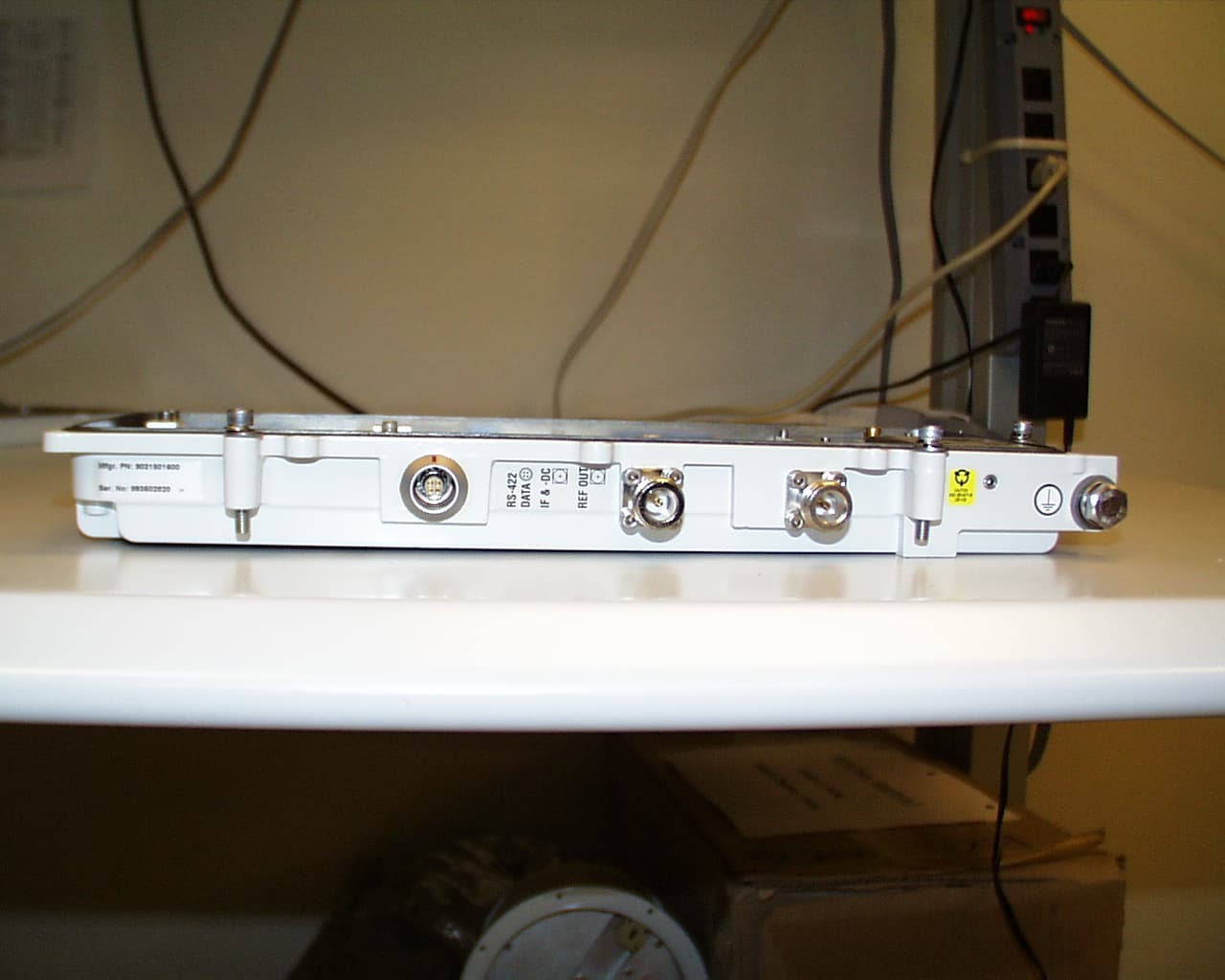
Click to zoom
Application Details
- Equipment Class
- TNB - Licensed Non-Broadcast Station Transmitter
- Date of Grant
- Sep 17, 2001
- Application Purpose
- Original Equipment
- Date of Application
- Jul 16, 2001
- Equipment Note
- Alcatel 7390 LMDS Broadband Wireless System - 31GHz
- Frequency Range
- 31225.00000000 - 31300.00000000
- Company
- Alcatel Canada Inc
- Country
- United States
Documents & Files
Document Text
Text extracted from the exhibit documents filed with the FCC. Open a document above to read the original.
Block Diagram
©Alcatel University - 8AS 90169 0002 VT ZZA Ed.1 March 2000Page 66 OBC MPC860 SAR MEMORY ( FLASH, SRAM, SDRAM ) INTERFACE OBC On Board Controller used on all ANT, TNT and AMD boards and in the NT subscriber terminal. 2 Ethernet ports 1 I2C port Air MoDem: AMD board has following functions like ATM and telepho nes circuits multiplexing/demultiplexing in the radio frame for a sector. Digital Video Broadband modulation in the downstream channel. Packet demodulation on four upstream channel. Radio resource management associated with this sector. Manages and transmits the alarms to the ANT.
Block Diagram
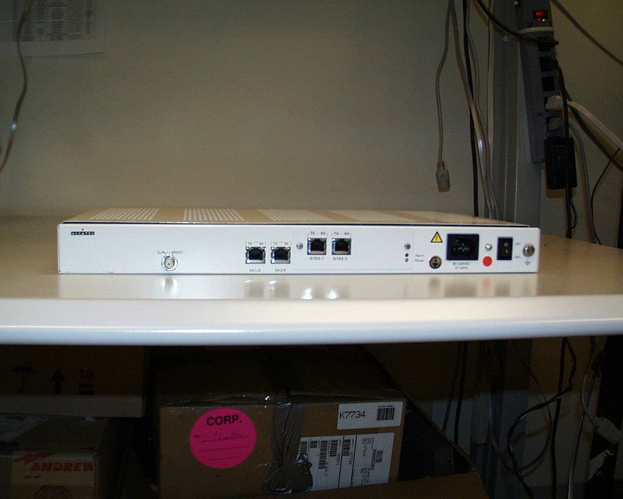
©Alcatel University - 8AS 90169 0002 VT ZZA Ed.1 March 2000Page 82 IBS board 1) Functionnalities IF converters Power supply RBS 2) Redundancy 3) Electrical features Station architecture I Q + _ + _ QPSK Modulator Isolation Transformers R F VCO synthesizer 950-2050 Mhz Digital control and status Output power sensing Voltage controlled attenuator Tx IF O/P 950-2050 Mhz From modem E Q E Q VREF From modem I+ I- Q+ Q- VREF Dig. Att. Protec- tion Voltage controlled Tuning filter VTune TX VTune TX TCXO Power Detection VTune TX-1 VTune TX-1 Out of lock detect Downstream (TX) Isolation Transformers To Modem 70 Mhz IF Identical tuned RX IF 400-900 Mhz RX1 RX2 Protec- tion VCO VTune RX TCXO synthesizer 700-1200 Mhz Digital control and Status VTune RX Synthesizer 370 MHz VCO Synthesizer 379 MHz VCO Digital Control From TCXO Digital Control From TCXO 300 MHz BP D/A D/A Level control DACS Digital Control filters Out of Lock det. Out of Lock det. To Digital Status To Digital Status Upstream (RX) IBS – Modulator and IF convertor The modulating waveform is a pair of baseband signals representing the inphase (I) and quadrature (Q) information of the QPSK signal. The waveforms are digitally generated. L-C lowpass filters after the DACs attenuate the sampling images and clock spurs. Conversion to IF is done directly using a monolithic integrated quadrature modulator IC containing the mixers and LO 90 degree phase splitter. The LO is generated at the carrier frequency by a frequency synthesizer programmable over the IF range of 950 -2050 MHz. The synthesizer is referenced to a 12 MHz TCXO with+/- 2.5 ppm stability over the temperature range 0 to 70 degree C. IF filters are very wide relative to the channel width of 36 MHz and attenuate harmonics of the carrier. The filter stopband is switchable to maintain suppression of the second harmonic as the carrier is tuned over the IF band. The tuner output level is maintained by a control loop monitoring a temperature compensated schottky diode detector. The loop maintains the carrier at a constant level over the IF band. The final output level from the tuner is controllable in 1 dB steps from +8 to -22 dBm via a digital attenuator.
Block Diagram
BPF 1025-1100 MHz PROPRIETARY INFORMATION 12/15/99 W/G BPF 31.225 GHz TO 31.300 GHz BIAS-T BPF BPF PA DC/DC CONVERTER MICRO- CONTROLLER RS-422 INTERFACE 100 MHz REFERENCE INPUT (FROM ORU) -48 VDC INPUT1025-1100 MHz X2 15.1 GHz BLOCK DIAGRAM, OTU US BAND B General Description RBS TX (OTU) 1. SC OP E This document establishes the general description for the functional performance of the frequency stability and control, spurio us suppression and power control requirements for the Outdoor Transmitter Unit (OTU).2. DESCRIPTION2.1. Frequency stability and control. The inte gral Local Osc illator (L.O.) is frequency locked to the reference oscillator source s upplied via the companion receiver unit. The frequency stab ility is guaranteed by the manufacturer to be +/- 8ppm over 17 years. 2.2. Spurious suppression. The radiated spurious emissions from the OTU, at the RF output port, are suppressed by the use of a waveg uide filter which rejects signals> 100 Mhz from either band edge by> 15 dB. The cutoff characteristics of WR-28 waveguide and the length of the filter r eject signals DC- 20 GHz by > 90dB. The LO level, LO harmonics and sub-harmonics is cut off by this filter and guaranteed to be less than -30 dBm. 2.3. Power control. The OTU output power is controlled by the equipment downstream of the IF input signal. An RS-422 interf ace can be used to monitor phase-locked-loop status. The output power can be turned off remotely though this interf ace if a non-compliant condition is detected. There is no limiting circuitry on the output power, however, the power amplifiers will saturate a few dB above the rated P1dB level.
Block Diagram
BIAS-T VVA AMP x2 AMP BPF 600-675MHz AMP LPF DC-2GHz ~ SPLITTER 100MHz REFERENCE DC/DC CONVERTER MICRO- CONTROLLER W/G BPF 31.000-31.075 GHz RS-422 INTERFACE100MHz REFERENCE OUTPUTIF OUTPUT 600-675MHz-48VDC INPUT 15.2GHz PLDRO BLOCK DIAGRAM, ORU US BAND-B − − − − 48VDC RF INPUT 31.000-31.075GHz (FROM ANTENNA) LNA IMAGE FILTER AMP LPF General Description RBS RX (ORU) 1. SC OP E This document establishes the general description for the functional performance of the frequency stability and control, spurio us suppression and power control requirements for the Outdoor R eceiver Unit (ORU). 2. DESCRIPTION 2.1 Frequency stability and control. The Local Oscillator (LO) frequency exhibits a stability/ accuracy of less than ± 8 parts per million (ppm) as a result of initial setting inaccuracy, temperature drift and aging over 10 years. The stability is achieved by phase-locking the LO to a stable 10 0 MHz reference oscillator that is internal to the ORU. The 100 MHz reference is an Ovenized Crystal Oscillator (OCXO) and the stability requirements guaranteed b y the OCXO manufacturer. Adjustment of the frequency of the crystal oscillator can be performed in one of two ways.a) Some oscillators employ a mechanical tuning adjustment that allows the frequency to be controlled within ± 4 ppm from the initia l setting. The mechanical tuning does not allow for frequency control after the unit has been sealed. b) Some oscillators employ a voltage controlled frequency adjustment that allows the frequency to be controlled within ± 3 ppm from the init ial setting over a voltage range of 0 to 5 VDC. The voltage control enables the frequency to be adjusted externally via the RS-422 interf ace. 2.2 Spurious suppression. Radiated spurious emissions from the ORU, at the RF input port, are suppressed by the use of pre–select f iltering. A standard WR-28 waveguide filter is employed which rejects signals > 125 MHz from either band edge by >25 dB.The cutoff characteristics of WR-28 waveguide and the length of the pre-select filter, reject signals DC – 20 GHz by > 90 dB.The fundamental LO leakage, LO harmonics and sub-harmonics at the RF input port are < 30 dBm. The use of the pre-select filter and the reverse isolation of the internal mixer and input amplifier achieve this. 2.3 Power Control. The ORU is a receiver and therefor there are no signals transmitted at the RF i nput port beyond the spurious emissions stated in section 2.2.
Cover Letter(s)
July 3, 2001 Federal Communicatio ns Co mmission EQUIPMENT APPROVAL SERVICES P.O. Box 358315 Pittsburgh, PA 15251-5315 Re fe re nce : Re que st for FCC Equipme nt Aut horiz ation Ce rtificatio n Alcatel Canada Incorporation is in the process of completing a new product for the Local Multipoint Distribution System (LMDS) band and has requested for a FCC Equipment Authorization Certification. The Form 731 has been completed and submitted to the FCC. These services, assigned to the 31,000 to 31,075 MHz and 31,225 to 31,300 MHz bands (US band B) are covered under Part 101: Fixed Microwave Services of the Federal Communications Commission Rules and Regulations. The product is called Alcatel 7390 Broadband Wireless System, which provides all the advantages of ATM (Asynchronous Transfer Mode). These advantages include the convergence of voice, data and video, scalability; and maintenance & control of quality of services to the customer site using cost effective microwave transmission. Company Name: Alcatel Canada Inc. Product Name:Alcatel 7390 LMDS Broadband Wireless System Frequency Range:31,000 – 31,075 MHz & 31,225 – 31,300 MHz Frequency Stability:± 10 PPM BS – Base Station Emission Designator:56M0DXW, 70M0DXW FCC ID#F9R31T28A04A22A. Confirmation #:EA101713 Rated RF Output Power:0.2 Watts TS – Terminal Station Emission Designator:3M50DXW, 7M00DXW FCC ID#F9R31T07A01A22B. Confirmation #:EA101715 Rated RF Output Power:0.05 Watts Address:600 March Road, Kanata, Ontario Canada K2K 2E6 Telephone:613-599-3600 Fax:613-599-3642 Contact:Daxesh Thakker Wireless Approvals Specialist 613-784-2464 [email protected] I hereby certify that this application was prepared to the best of my knowledge and belief, and the accompanying information/ exhibits are true & correct. Sincerely, Daxes h T ha kker
Cover Letter(s)
July 3, 2001 Federal Communications Commission EQUIPMENT APPROVAL SERVICES P.O. Box 358315 Pittsburgh, PA 15251-5315 Reference: Request for Confidentiality Alcatel Canada Inc. is in the process of completing a new product for Local Multipoint Distribution System (LMDS) band and has requested for the FCC to keep certain documents confidential. The list below mentions the documents that need be keep confidential due to non-disclosure agreements with our OEM suppliers. Company Name: Alcatel Canada Incorporation Product Name: Alcatel 7390 LMDS Broadband Wireless System BS – Base Station Emission Designator:56M0DXW, 70M0DXW FCC ID#F9R31T28A04A22A. Confirmation #:EA101713 Rated RF Output Power:0.2 Watts TS – Terminal Station Emission Designator:3M50DXW, 7M00DXW FCC ID#F9R31T07A01A22B Confirmation #:EA101715 Rated RF Output Power:0.05 Watts Address:600 March Road, Kanata, Ontario Canada K2K 2E6 Telephone:613-599-3600 Fax:613-599-3642 Contact: Daxesh Thakker Wireless Approvals Specialist 613-784-2464 Email: [email protected] Daxesh Thakker Wireless Approvals Specialist Alcatel Canada Incorporation 613-784-2464 List of Material to maintain Confidential A. BaseStation (BS) • All Schematics (PDF file format) for the AMD, the IBS, the RBS TX (OTU) and the RBS RX (ORU) • All Bill of Materials (XLS file format)for the AMD, the IBS, the RBS TX (OTU) and the RBS RX (ORU) B. Terminal Station (TS) • All Schematics (PDF file format) for the NT and the RT (OTRU) • All Bill of Materials (XLS file format) for the NT and the RT (OTRU)
Cover Letter(s)
July 20, 2001 Federal Communications Commission EQUIPMENT APPROVAL SERVICES P.O. Box 358315 Pittsburgh, PA 15251-5315 Reference: Request to change the SR.NO. of the RBS TX. (OTU) from C 002028259 to 993574482 in the “Test Report of Base Station for Approvals” file. (Page no. 11 in the test report) Alcatel Canada Incorporation is in the process of completing a new product for the Local Multipoint Distribution System (LMDS) band and has requested for a FCC Equipment Authorization Certification. The Form 731 has been completed and submitted to the FCC. I request you to change the SR.NO. of the RBS TX. (OTU) from C 002028259 to 993574482 in the “Test Report of Base Station for Approvals” file submitted on JULY 18, 2001 in Microsoft Word file format. (Page no. 11 in the test report). Thank you very much. Best regards, Sincerely, Daxesh Thakker Wireless Approvals Specialist Alcatel Canada Inc.
Operational Description
Alcatel LMDS Solution Technical description 1ALCATEL 7390 LMDS Technical Description ---- System CONTENTS 1 - INTRODUCTION ........................................................................................................................ 1 1.1 - MARKET CONSIDERATIONS.............................................................................................. 1 1.2 - ALCATEL LMDS MAIN FEATURES ...................................................................................... 2 2 - ARCHITECTURE......................................................................................................................... 3 2.1 - GENERAL ........................................................................................................................ 3 2.2 - ARCHITECTURE............................................................................................................... 4 1 - INTRODUCTION 1.1 - MARKET CONSIDERATIONS Fixed wireless radio technology offers a cost-effective solution for densely-populated urban and suburban areas. High-capacity wireless local loop systems enable operators to rapidly provide a range of voice and data services to large numbers of customer sites. Point-to-Multipoint (PMP) wireless systems can also provide an attractive solution for mobile network operators seeking to link mobile base stations and controllers in busy downtown areas. What is more, a combined fixed and mobile operator can interconnect both customer sites and cellular base stations using the same fixed broadband wireless system. The Alcatel LMDS range of products meets the need for a broadband PMP wireless system which can be used profitably by both incumbent and new telecom operators, cable TV system operators, and other wireless network providers. Because it is a member of Alcatel’s extensive portfolio of products, it can be deployed as part of a fully integrated network solution which includes: - Synchronous Digital Hierarchy (SDH) / Synchronous Optical Network (SONET) transmission technologies (fiber or radio) and ATM-based services - Narrowband/broadband switches. - Broadband Remote Access Node (RAN). - Cellular/Wireless Local Loop products. - Voice interconnection systems, such as SS7, V5.2 and TR-303 - Fullly integrated Network and Service Management. 1.2 - ALCATEL LMDS MAIN FEATURES The following is a list of the valuable features that the Alcatel LMDS system offers: - Microcellular point-to-multipoint distribution architecture. - Broadband Wireless Network using internal Asynchronous Transfer Mode (ATM) Transport. - Voice, data,IP and integration at very high speeds. - Medium Access Control (MAC) which supports ATM Quality of Service and advanced IP CoS - Efficient packet and voice transport with minimal throughput delay - Dynamic Bandwidth Allocation (DBA) of services “over-the-air” with user definable contracts - Multiple Quality of Service class support - Both single carrier and multiple carrier architecture via cross pole or co-pole radio solutions - Multiple frequency bands, type approved for world-wide use - Sectored base station antennas - High frequency re-use between sectors and cells. - Large global range of downstream channeling: 14 and 28 MHz. - Flexible, high throughput upstream channeling: 3.5 and 7MHz . - Customer site Network Terminations providing: POTS/ISDN switched services, nx64 kbits/s - nxE1/T1 leased lines standard and advanced Ethernet 10BaseT/100BaseT interfaces with Dynamic Bandwidth Allocation - Base Stations, with full redundancy providing network interfaces such as: ATM (OC3/STM1/E3/T3) for data connection and optional n x E1/T1 for services such as telephony orleased lines. - Indoor and outdoor Base Station installations - Advanced support for business-class IP services, for example VLANs, IP service priority, Service Contracts system and support of DiffServ - Advanced Network and Service Management which includes Simple Network Management Protocol (SNMP) based Network Management System (NMS) using HP OpenView and integrated in the advanced Alcatel Management platform. The best interests of both Service Providers and manufacturers are served by implementing well- recognized International standards. Therefore, the system is implemented according to DAVIC standards at the IF level. Alcatel is active in both the ETSI and IEEE working parties for modulation and physical standardization. Future releases of the Broadband Access platform will conform to these standards when harmonized. 2 - ARCHITECTURE 2.1 - GENERAL The Alcatel LMDS is a high capacity, flexible point-to-multipoint broadband wireless solution, designed to meet the requirements of service providers who need to offer a mix of traditional and new exiting high speed services, to a mix of business and residential customers. Broadband wireless is inherently faster to deploy than traditional wireless services and the Alactel LMDS has specifically enhanced features to ensure rapid planning and deployment of both cell sites and customer premises. The advanced Network and Service Management solution offered total end-to-end management with the collection of statistical and billing information. The ability to offer full “flow-through-provisioning” is a key feature in the reduction of operational expense by the service provider, the Alcatel LMDS ensures traditional and new services and applications can be supplied cost effectively, with the minimum of technical and operational staff involved. The Alcatel LMDS has been designed with a highly flexible channel allocation plus supports a wide range of radio frequency variants, either in a cross-polar or co-polar configuration, with very high frequency re-use. This ensures that service providers maximize their investment in the valuable radio spectrum and are assured that initial deployments are cost effective and customer growth can be achieved easily. The Alcatel LMDS enables service providers to cater for the small to medium business user, either in…
Text truncated - open the document above for the full version.
Contact Information
Applicant
Genevieve Silveroli(VP and Head of Legal Compliance)
Technical Contact
Technical Specifications
| # | Rule Parts | Frequency Range | Power Output | Emission | Tolerance |
|---|---|---|---|---|---|
| 2 | 101 | 31.23 GHz - 31.30 GHz | 200.00 mW | 70M0DXW | 10 ppm |
Other Applications from Alcatel Canada Inc
F9R39T07A01B22B
Dec 12, 2001Alcatel 7390 LMDS Multiservice Broadband WIreless
Equipment Class
TNB - Licensed Non-Broadcast Station Transmitter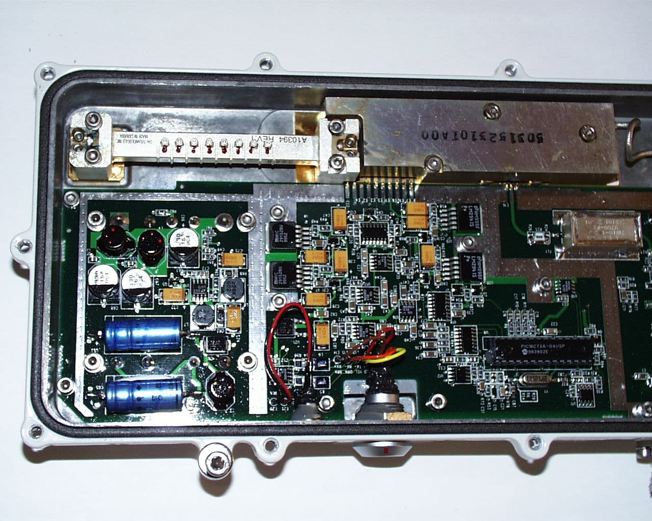
F9R39T28A03A22A
Dec 10, 2001Alcatel 7390 LMDS Multiservice Broadband Wireless
Equipment Class
TNB - Licensed Non-Broadcast Station Transmitter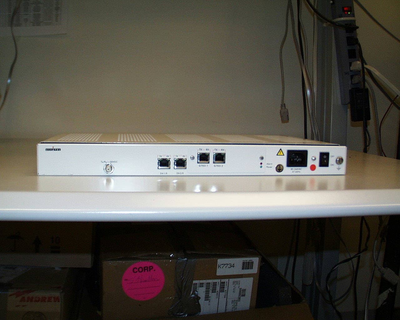
F9R31T07A01A22B
Sep 16, 2001Alcatel 7390 LMDS Broadband Wireless System - 31GHz
Equipment Class
TNB - Licensed Non-Broadcast Station Transmitter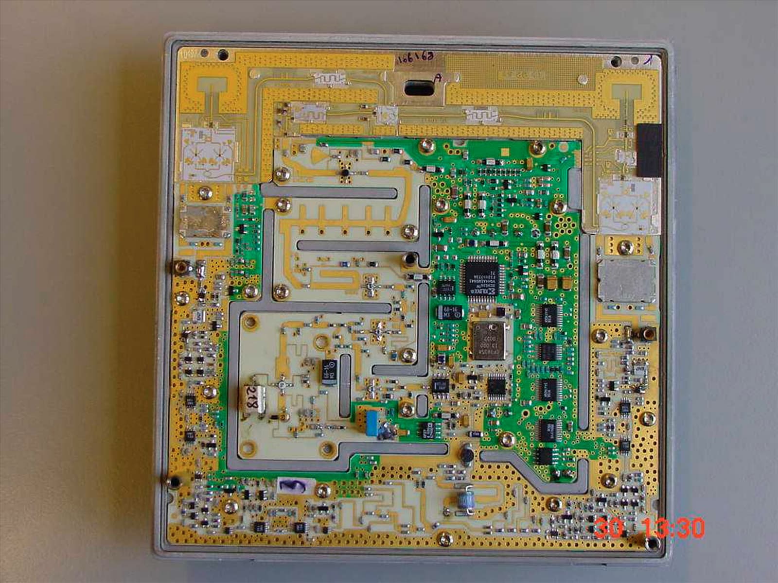
F9R24T07A01D22D
Aug 26, 20017390 24 GHz Co-Pol RT
Equipment Class
TNB - Licensed Non-Broadcast Station Transmitter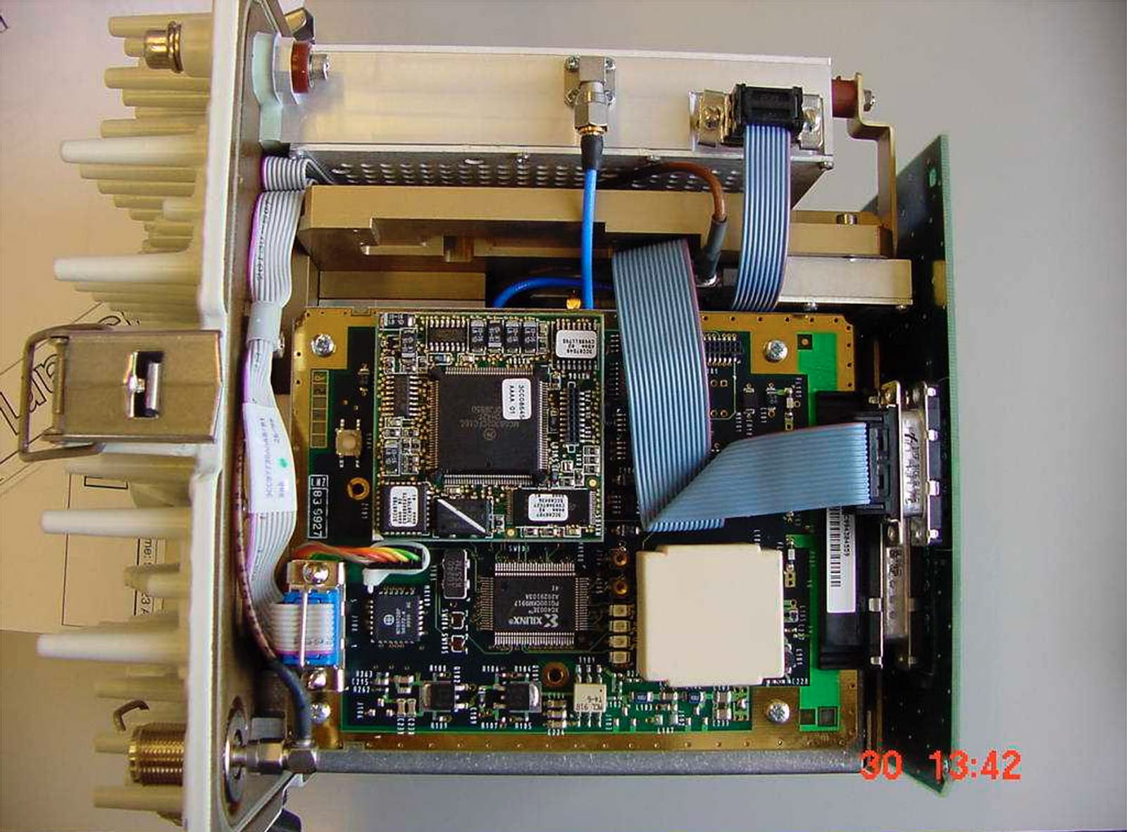
F9R24T28A01D22C
Aug 23, 20017390 24 GHz Co-Pol RBS
Equipment Class
TNB - Licensed Non-Broadcast Station Transmitter