F9R39T28A03A22AAlcatel 7390 LMDS Multiservice Broadband Wireless
Alcatel Canada Inc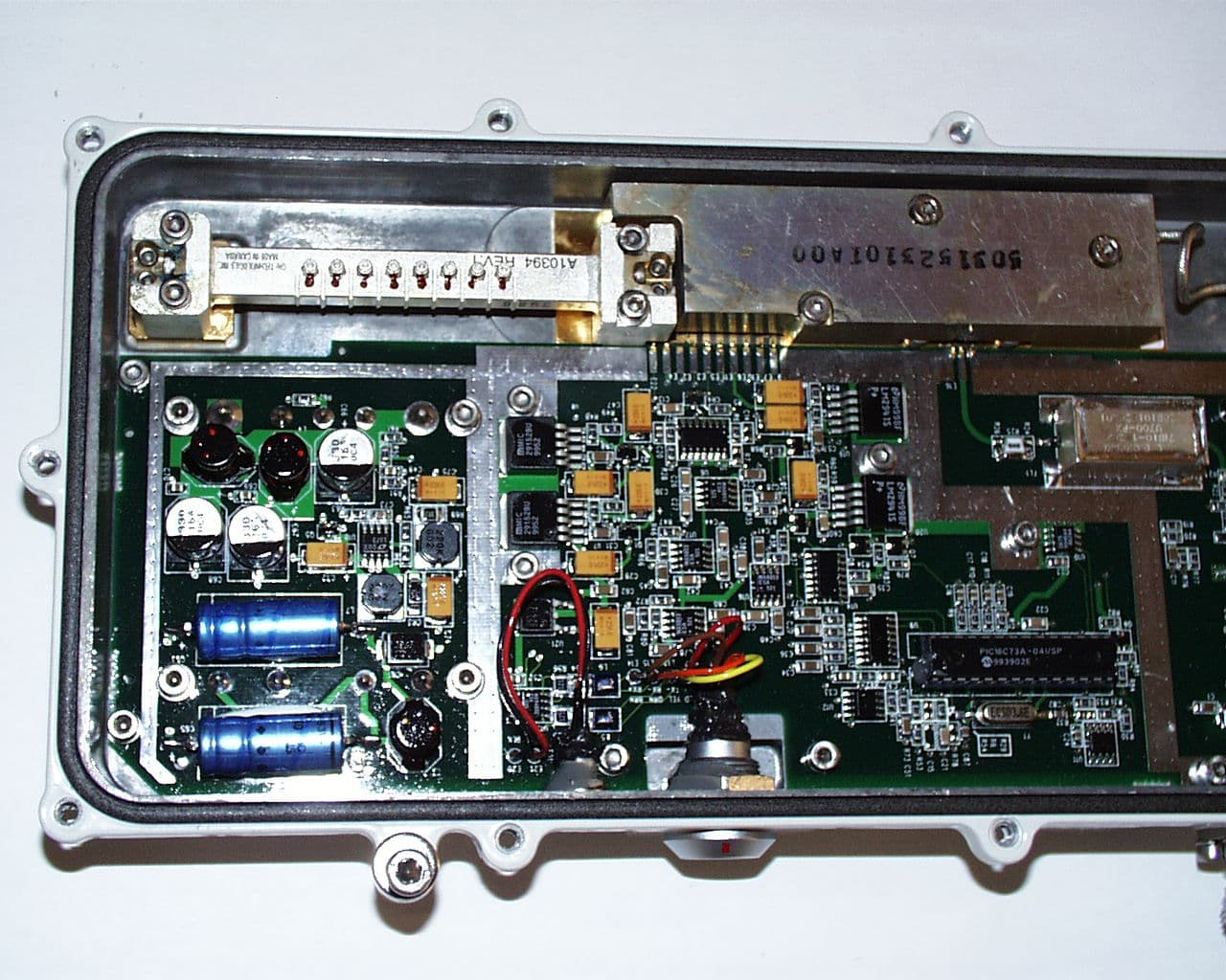
Click to zoom
Application Details
- Equipment Class
- TNB - Licensed Non-Broadcast Station Transmitter
- Date of Grant
- Dec 10, 2001
- Application Purpose
- Original Equipment
- Date of Application
- Oct 23, 2001
- Equipment Note
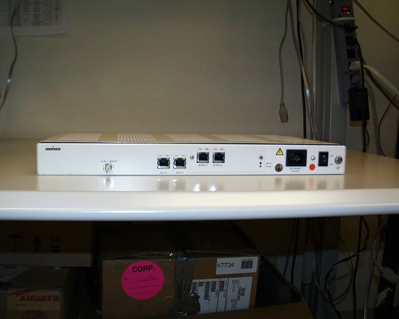
- Alcatel 7390 LMDS Multiservice Broadband Wireless
- Frequency Range
- 39300.00000000 - 40000.00000000
- Company
- Alcatel Canada Inc
- Country
- United States
Documents & Files
Document Text
Text extracted from the exhibit documents filed with the FCC. Open a document above to read the original.
Users Manual
3CC12426AAAA TQ BJA Ed. 01 A AA Al ll lc cc ca aa at tt te ee el ll l 7 77 73 33 39 99 90 00 0 Multiservice broadband wireless access solution Base Station - release 2.2b ( (( (E EE Ex xx x 9 99 99 99 90 00 00 00 0) )) ) X - Polarized version User Manual 2/346Issue 01 - April 2001 - Draft 043CC12426AAAA TQ BJA 01 4 Status Draft Change Note Short TitleA7390 Base Station – release 2.2b All rights reserved. Passing on and copying of this document, use and communication of its contents not permitted without written authorization from Alcatel. 3CC12426AAAA TQ BJA 01Issue 01 - April 2001 - Draft 043/346 4 Customer Service Support: a Team tuned to your needs for your entire satisfaction Congratulations on having bought your equipment from Alcatel. We hope that it will give you full satisfaction. For any additional information or if you have any questions concerning this equipment, please contact the Technical Assistance Center, (TAC) dedicated to your support whose coordinates have been given to you by the Alcatel Contract Manager or: http://www.cid.alcatel.com/support . You must specify the hardware and software configurations of each item concerned when getting in touch. This service, available on subscription, is free for the duration of the initial waranty period. 4/346Issue 01 - April 2001 - Draft 043CC12426AAAA TQ BJA 01 4 PAGE INTENTIONALLY LEFT BLANK 3CC12426AAAA TQ BJA 01Issue 01 - April 2001 - Draft 045/346 10 Table of contents 1 – Foreword . . . . . . . . . . . . . . . . . . . . . . . . . . . . . . . . . . . . . . . . . . . . . . . . . . . . . . . . . . . . . . . . . . 11 1.1 – Structure of the manual . . . . . . . . . . . . . . . . . . . . . . . . . . . . . . . . . . . . . . . . . . . . . . . . . . . 11 1.2 – Using the manual. . . . . . . . . . . . . . . . . . . . . . . . . . . . . . . . . . . . . . . . . . . . . . . . . . . . . . . . 11 1.3 – Safety instructions . . . . . . . . . . . . . . . . . . . . . . . . . . . . . . . . . . . . . . . . . . . . . . . . . . . . . . . 12 1.3.1 – General rules . . . . . . . . . . . . . . . . . . . . . . . . . . . . . . . . . . . . . . . . . . . . . . . . . . . . . 12 2 – Equipment overview . . . . . . . . . . . . . . . . . . . . . . . . . . . . . . . . . . . . . . . . . . . . . . . . . . . . . . . . . 19 2.1 – Overview of the A7390 system . . . . . . . . . . . . . . . . . . . . . . . . . . . . . . . . . . . . . . . . . . . . . 19 2.2 – Composition of the A7390 system . . . . . . . . . . . . . . . . . . . . . . . . . . . . . . . . . . . . . . . . . . . 20 2.3 – A7390 system specifications . . . . . . . . . . . . . . . . . . . . . . . . . . . . . . . . . . . . . . . . . . . . . . . 21 2.3.1 – Frequency bands used . . . . . . . . . . . . . . . . . . . . . . . . . . . . . . . . . . . . . . . . . . . . . 21 2.3.2 – Radio transmission specifications (typical values) . . . . . . . . . . . . . . . . . . . . . . . . 21 2.3.3 – Capacity. . . . . . . . . . . . . . . . . . . . . . . . . . . . . . . . . . . . . . . . . . . . . . . . . . . . . . . . .22 2.3.4 – X-Pol RBS Tx and X-Pol RBS Rx . . . . . . . . . . . . . . . . . . . . . . . . . . . . . . . . . . . . . 24 2.3.5 – Bias-T . . . . . . . . . . . . . . . . . . . . . . . . . . . . . . . . . . . . . . . . . . . . . . . . . . . . . . . . . . 25 2.3.6 – Surge protectors . . . . . . . . . . . . . . . . . . . . . . . . . . . . . . . . . . . . . . . . . . . . . . . . . . 26 2.3.7 – Cables . . . . . . . . . . . . . . . . . . . . . . . . . . . . . . . . . . . . . . . . . . . . . . . . . . . . . . . . . .27 2.4 – Installing the base station components . . . . . . . . . . . . . . . . . . . . . . . . . . . . . . . . . . . . . . . 31 2.4.1 – BS site requirements . . . . . . . . . . . . . . . . . . . . . . . . . . . . . . . . . . . . . . . . . . . . . . . 31 2.4.2 – BS installation overview. . . . . . . . . . . . . . . . . . . . . . . . . . . . . . . . . . . . . . . . . . . . . 33 2.4.3 – Equipment and cable connection for non-redundant and redundant X-Pol RBS Tx/X-Pol RBS Rx configurations . . . . . . . . . . . . . . . . . . . . . . . . . . . . . 36 2.4.4 – BS installation tasks . . . . . . . . . . . . . . . . . . . . . . . . . . . . . . . . . . . . . . . . . . . . . . . 38 2.5 – Installing BS X-Pol RBS Txs, X-Pol RBS Rxs and antennas. . . . . . . . . . . . . . . . . . . . . . . 38 2.5.1 – Overview . . . . . . . . . . . . . . . . . . . . . . . . . . . . . . . . . . . . . . . . . . . . . . . . . . . . . . . .38 2.5.2 – Attaching an X-Pol RBS Tx or X-Pol RBS Rx to an antenna. . . . . . . . . . . . . . . . . 39 2.5.3 – Attaching a mounting plate and antenna to a pole . . . . . . . . . . . . . . . . . . . . . . . . 42 2.5.4 – Replacing an X-Pol RBS Tx, X-Pol RBS Rx or antenna . . . . . . . . . . . . . . . . . . . . 48 2.6 – Installing Bias-Ts and surge protectors . . . . . . . . . . . . . . . . . . . . . . . . . . . . . . . . . . . . . . . 49 2.6.1 – Replacing the gas discharge tube in a surge protector . . . . . . . . . . . . . . . . . . . . . 51 2.7 – Installing Type N lightning arresters . . . . . . . . . . . . . . . . . . . . . . . . . . . . . . . . . . . . . . . . . 52 2.8 – BS cables connections . . . . . . . . . . . . . . . . . . . . . . . . . . . . . . . . . . . . . . . . . . . . . . . . . . .55 2.8.1 – Selecting BS IF cables . . . . . . . . . . . . . . . . . . . . . . . . . . . . . . . . . . . . . . . . . . . . . 59 2.8.2 – Marking IF cables for identification . . . . . . . . . . . . . . . . . . . . . . . . . . . . . . . . . . . . 61 2.8.3 – Cable strain relief. . . . . . . . . . . . . . . . . . . . . . . . . . . . . . . . . . . . . . . . . . . . . . . . . . 64 2.8.4 – Connecting BS IF cables . . . . . . . . . . . . . . . . . . . . . . . . . . . . . . . . . . . . . . . . . . . . 65 2.8.5 – Connecting the RS-422 data cables . . . . . . . . . . . . . . . . . . . . . . . . . . . . . . . . . . . 68 2.8.6 – Connecting SMA cables . . . . . . . . . . . . . . . . . . . . . . . . . . . . . . . . . . . . . . . . . . . . 70…
Text truncated - open the document above for the full version.
Users Manual
3CC12426AAAA TQ BJA 01Issue 01 - April 2001 - Draft 0441/346 104 Figure 10 – Antenna, X-Pol RBS Tx/X-Pol RBS Rx and captive bolts 5. As shown in Figure 11, place a lock washer and a flat washer on each of the four RF wave guide screws, and insert and tighten each of the four screws to 0.56 Nm (5 in.-lb) torque. Figure 11 – Installing the RF wave guide screws 6. Ensure that each of the captive screws and RF wave guide screws are tightened to the correct torque, and that there is no gap between the radio and antenna. Antenna Captive bolt (hidden) O-ring X-Pol RBS TX X-Pol RBS Rx Antenna RF wave guide screw Flat washer Lock washer X-Pol RBS Tx X-Pol RBS Rx Captive bolts 42/346Issue 01 - April 2001 - Draft 043CC12426AAAA TQ BJA 01 104 2.5.3 – Attaching a mounting plate and antenna to a pole The following parts are required: – an antennna with an attached X-Pol RBS Tx or X-Pol RBS Rx, – a single-antenna mounting plate and mounting hardware (provided with the antenna), or a dual- antenna mounting plate and mounting hardware (part number 90-7385-02). The BS mounting hardware is composed of the following: – downtilt adjustment screws, – flat washers, – lock washers, – antenna bolts, – U-bolts and U-bolt brackets, – 17 mm nuts. The dual antenna mounting plate can accommodate either one or two antennas. Single-antenna configurations are used for non-redundant X-Pol RBS Tx or X-Pol RBS Rx operation, and double- antenna configurations are used for redundant X-Pol RBS Tx or X-Pol RBS Rx operation. To connect a mounting plate and antenna to a pole 1. Attach the mounting plate to the pole using the pole mounting hardware, as shown in Figure 12, where a single antenna mounting plate is shown. 1. Thread the downtilt adjustment screw(s) into the mounting plate until the hole in the adjustment screw plate aligns with the antenna bolt channel at the top of the mounting plate. 2. Connect the top of the mounting plate to the pole using a U-bolt, U-bolt bracket, washers and nuts. 3. Tighten the two nuts until the top of the mounting plate is held securely to the pole, but is still shifts enough from side-to-side to allow the bottom U-bolt to be inserted. 4. Connect the bottom of the mounting plate to the pole using a U-bolt, U-bolt bracket, washers and nuts. 5. Tighten all four U-bolt nuts to 54.4 Nm, ± 2.7 Nm (40 ft-lb, ± 2 ft-lb) of torque. Warning - If an antenna is attached to a mounting plate on a pole before an X-Pol RBS Tx or X-Pol RBS Rx is attached to the antenna, the RF wave guide and screws must be covered with weatherproof tape to protect the antenna from moisture. Caution - Do not install an X-Pol RBS Tx and an X-Pol RBS Rx on the same mounting plate, otherwise the X-Pol RBS Tx transmit signal will interfere with the X-Pol RBS Rx receive signal. Caution - Mounting poles should be grounded to a suitable lightning discharge ground. 3CC12426AAAA TQ BJA 01Issue 01 - April 2001 - Draft 0443/346 104 Figure 12 – Connecting the mounting plate to the pole 2. Connect the antenna to the mounting plate, as shown in Figure 13. Downtilt adjustment screw Screw bracket U-bolt U-bolt bracket Nut Lock washer Flat washer Mounting pole Mounting plate 44/346Issue 01 - April 2001 - Draft 043CC12426AAAA TQ BJA 01 104 Figure 13 – Connecting the antenna to the mounting plate 1. Thread a nut roughly 10 mm (3/4 in.) onto each of the two antenna bolts. 2. Connect the top of the antenna to the top of the mounting plate by inserting one of the antenna bolts through a lock washer, a flat washer, the adjustment screw plate, antenna bolt channel on the mounting plate, a spacer and upper bolt hole on the antenna. Add a flat washer, a lock washer and a nut to the antenna side of the antenna bolt, and tighten both nuts to 54.4 Nm, ± 2.7 Nm (40 ft-lb, ± 2 ft-lb) of torque. 3. Connect the bottom of the antenna to the bottom of the mounting plate by inserting the remaining antenna bolt through a lock washer, a flat washer, the antenna bolt hole on the mounting plate, a spacer and the lower bolt hole on the antenna. Add a flat washer, a lock washer and a nut to the antenna side of the antenna bolt, and tighten both nuts to 54.4 Nm, ± 2.7 Nm (40 ft-lb, ± 2 ft- lb) of torque. To mount a second antenna on a dual antenna mounting plate A second antenna can be attached to a dual antenna mounting plate, as shown in Figure 14. Nut Lock washer Flat washer Spacer Antenna bolt 10mm (3/4 in.) Nut Antenna Lock washer Flat washer Spacer Antenna bolt and nut 3CC12426AAAA TQ BJA 01Issue 01 - April 2001 - Draft 0445/346 104 Figure 14 – Mounting a second antenna 1. Thread a nut roughly 10 mm (3/4 in.) onto each of the two antenna bolts. 2. Connect the top of the antenna to the top of the mounting plate by inserting one of the antenna bolts through a lock washer, a flat washer, mounting plate antenna bolt channel, the adjustment screw plate, a spacer and the upper antenna bolt hole. Add a flat washer, a lock washer and a nut to the antenna side of the antenna bolt, and tighten both bolts to 54.4 Nm, ± 2.7 Nm (40 ft-lb, ± 2 ft-lb) of torque. 3. Connect the bottom of the antenna to the bottom of the mounting plate by inserting the remaining antenna bolt through a lock washer, a flat washer, the lower mounting plate antenna bolt hole, a spacer and lower antenna bolt hole. Add a flat washer, a lock washer and a nut to the antenna side of the antenna bolt, and tighten both bolts to 54.4 Nm, ± 2.7 Nm (40 ft-lb, ± 2 ft-lb) of torque. To ground the X-Pol RBS Tx or X-Pol RBS Rx The following parts and supplies are required: – an adequate length of ground conductor, – an M8 ring lug, – dielectric paste. 1. Measure a length of ground conductor sufficient to run from the X-Pol RBS Tx or X-Pol RBS Rx to the nearest suitable ground point. The required diameter, metal type and physical type of the ground conductor may vary according to local regulations. Consult local electrical authorities for information. 2. Connect an uninsulated M8 ring lug connector securely to on…
Text truncated - open the document above for the full version.
Users Manual
3CC12426AAAA TQ BJA 01Issue 01 - April 2001 - Draft 0481/346 104 9. Set the DMC crimping tool to position 4 (for 24 AWG wire), and give the positioner a clockwise twist to ensure that it is set properly and will crimp the contact pins on four sides. 10. Place a contact pin on a lead and check that the lead is inserted completely by looking in the hole in the contact pin; see Figure 51. There should be no more than 1 mm (0.04 in.) of exposed conductor protruding from the pin. Insert the pin into the DMC tool as far as it can go, and crimp the pin. The DMC tool has a ratchet mechanism that does not release until the pin has been crimped properly. Repeat this step for each lead. Figure 51 – Attaching a contact pin 11. Arrange the four pins as indicated in Figure 52, and insert them simultaneously into the insert; the pins enter the side of the insert that has the white marking. The pins must be inserted simultaneously because the conductors are not long enough to be inserted one at a time. Push each pin until it clicks into position, then confirm that contact is secure by gently pulling on the conductor. The white marking on the insert identifies the pins. The white circle identifies pin 1, and pins 2, 3 and 4 follow counterclockwise. Use the removal tool if the pins are in the wrong holes. Figure 52 – Inserting the contact pins 12. Put the insert into the insert carrier; see Figure 53. When assembled properly, the tab on the carrier faces towards the pins, the tab on the insert fits in the cutout in the carrier, and the bevel in the carrier fits on the bevel on the cone washer. The mat- ching bevels pinch the braided shielding when the connector is completely assembled. Contact pin Conductor Inspection hole White marking Pin 1 Tx+ White (Blue) Pin 4 Rx- White (Orange) Pin 2 Rx+ Orange Pin 3 Tx- Blue 82/346Issue 01 - April 2001 - Draft 043CC12426AAAA TQ BJA 01 104 Figure 53 – .Putting the insert into the insert carrier 13. Put the insert carrier into the connector body; see Figure 54. The red dot on the outer shell aligns with the tab on the insert carrier. You should feel a slight click when the carrier locks into place. It may be necessary to gently push the cable while carefully rotating the connector body until the click is felt. Figure 54 – Inserting the insert carrier into the outer shell 14. Tighten the connector by turning the collet nut to 6.9 Nm (5 ft-lb) of torque; see Figure 55. Do not rotate the connector body. Figure 55 – Tightening the connector 15. Push the bend relief on to the collet nut. Insert carrier Bevel Cutout in carrier Pins Tab on insert Tab on carrier Insert Tab on insert carrier Red dot Do not turn 3CC12426AAAA TQ BJA 01Issue 01 - April 2001 - Draft 0483/346 104 2.9 – Installing an L4PNM Heliax connector 2.9.1 – Overview The following parts are required: – Heliax LDF4 cable. – Heliax L4PNM connector (solder-connect or ring-flare variant). All tools and hardware required for this procedure except wrenches and soldering tools should be ordered from Heliax. See Appendix A for details. 2.9.2 – To add a solder-connect L4PNM connector 1. Strip 51 mm (2 in.) or more of the cable jacket from the IF cable, ending at the lowest point of a valley between two corrugations, as shown in Figure 56. Figure 56 – Removing the insulation 2. Install the O-ring on the first corrugation valley as shown in Figure 57. Figure 57 – Installing the small O-ring Note - Newbridge Broadband Wireless equipment should only be installed by qualified individuals who are trained and certified for the type of installation task assigned to them. Note - This step can be done more accurately and quickly if Heliax cable tool 207886 is used to score the cable jacket and cut the outer conductor. 51 mm (2 in.) or greater Outer conductor Lowest point between corrugations O-ring Cable jacket 84/346Issue 01 - April 2001 - Draft 043CC12426AAAA TQ BJA 01 104 3. Use a small grease brush to lubricate the O-ring with the silicone grease shipped with the connector. 4. Install the clamping nut on the cable by sliding it over the cable end until it is stopped by the O-ring. The fingers of the clamping nut should stop exactly half-way through a corrugation peak, as shown in Figure 58. Figure 58 – Installing the clamping nut 5. Remove the portion of outer conductor that is not covered by the clamping nut. 1. Use a fine-tooth saw to cut through the outer conductor flush with the clamping nut fingers. Do not cut deeper than the outer conductor, and make sure that the cut is made along the entire circumference where the clamping nut fingers meet the outer conductor; see Figure 59. Figure 59 – Cutting the outer conductor 2. Grasp the outer conductor with pliers, and carefully pull it off. When removed, the foam dielectric is exposed, as seen in Figure 60. Figure 60 – Foam dielectric Note - Substep i is unnecessary if Heliax cable tool 207886 was used in step 1 to score the cable jacket, and cut the outer conductor. If the Heliax cable tool was used, proceed to substep 2. Clamping nut Foam dielectric 3CC12426AAAA TQ BJA 01Issue 01 - April 2001 - Draft 0485/346 104 6. Remove the foam dielectric from the inner conductor. 1. Use a knife to cut the foam dielectric flush with the outer conductor, to the depth of the inner conductor, then cut along the length of the inner conductor several times until all the foam dielectric is removed from the inner conductor; see Figure 61. Figure 61 – Removing the foam dielectric 2. Use a knife to carefully scrape any remaining dielectric foam adhesive from the inner conductor. Be careful not to damage the inner conductor. 7. Trim the inner conductor. 1. Use a fine-tooth saw to trim the inner conductor to 5 mm (7/32 in.) from the outer conductor and clamping nut fingers, as shown in Figure 62. 2. Use a small file to remove any burrs on the end of the inner conductor. 3. Use a clean wire brush to remove any debris from the foam dielectric. 86/346Issue 01 - April 2001 - Draft 043CC12426AAAA TQ B…
Text truncated - open the document above for the full version.
Users Manual
3CC12426AAAA TQ BJA 01Issue 01 - April 2001 - Draft 04101/346 104 DesignationDescriptionStandardsObservations Physical interfaces: ATM network interface optical Connector typeSC/PC socket 1300 nm 1 for each direction Media Single-mode Fiber (SMF; 9/125 μm) 1300 nm 1 for each direction EnvironmentLaser product Class 1 Bit rate Nominal155.520 Mbps Timing± 20 ppm Free run mode, i.e. under synchronization source fault conditions Line codingNRZ JitterRefer to standard masks SignallingUNI 4.0 Physical interfaces: E3 G703 (34 Mbps) (75 W) Connector type 75W interface1,6/5,6 Media 75W interfaceCoaxial cable Environment Safety EMC/EMI Bit rate Nominal34.368 Mbps Tolerance± 20 ppm Line codingHDB3 JitterRefer to standard masks Input tolerated jitter Output residual jitter 102/346Issue 01 - April 2001 - Draft 043CC12426AAAA TQ BJA 01 104 DesignationDescriptionStandardsObservations Physical interfaces: E1, TDM circuit interface (75/120 W) Connector type DBS StandardSub-D/37 pins/fem. 8 connectors; 8 TDM interfaces per connector 75W interfaceBNC or 1,6/5,61 for each direction 120W interfaceSTP specific connector1 for each direction Media 75W interfaceCoaxial cable1 pair for each direction 120W interfaceSTP1 pair for each direction Environment Safety EMC/EMI Bit rate Nominal2.048 MbpsSynchronous stream Tolerance± 50 ppmUnder synchronization source fault conditions Line codingHDB3 JitterRefer to standard masks Input tolerated jitter Output residual jitter 3CC12426AAAA TQ BJA 01Issue 01 - April 2001 - Draft 04103/346 104 2.12.3– Common characteristics of the X-Pol RBS and DBS DesignationDescriptionStandardsObservations Physical interfaces: T1 , TDM circuit interface (100 W) Connector type 100W interfaceSub-D 37 points Media 100W interfaceShielded twisted Pair Bit rate Nominal1.544 Mbit/s Tolerance± 32 ppm Line codingAMI or B8ZSSoftware configurable JitterRefer to standard masks Input tolerated jitter Output residual jitter Environmental specifications DBS Classification-- Operating temperature -5°C to +55°C- Relative humidity at 30°C 93% DesignationDescriptionStandardsObservations Logistics TransportPublic transport: class 2.3- Ambient temperature-40°C to+ 70°C- Relative humidity at 55°C 95%- StorageClass 1.2 storage premises sheltered from the weather, without air- conditioning Ambient temperature-40°C to + 70°C- 104/346Issue 01 - April 2001 - Draft 043CC12426AAAA TQ BJA 01 104 2.13– Equipment power consumption 2.13.1– X-Pol RBS The typical power consumption of the X-Pol RBS is 31 W and X-Pol RBS Tx ¾ 50W, X-Pol RBS Rx ¾ 24W. 2.13.2– DBS Relative humidity at 30°C Condensation 100% 90 to 100 % - DBS configuration typeTypical power consumption basic configuration (1 sector, 1+0)130 W per additional sector100 W 1+1 redundancy (per sector)100 W ANT board (per board)25 W TNT board (per board)30 W DesignationDescriptionStandardsObservations 3CC12426AAAA TQ BJA 01Issue 01 - April 2001 - Draft 04105/346 128 3 – Installation of the Base Station 3.1 – Equipment delivery When you receive the equipment in its packaging: – check the condition of the packaging, – if damaged, make your reservations known to the carrier without delay. 3.1.1 – Labels on the equipment and the packaging Figures given on the examples below are not contractual. The RBS labels are affixed to the packaging and to the equipment to indicate its contents. Figure 83 – Example of a label for the RBS unit The DBS labels are fixed to the packaging to indicate its contents on leaving the factory.These labels are not affixed to the equipment because the DBS configuration changes in accordance with the site modifications. } } – 0,6 *3CC09766ACAA 01* 25 / 07 / 1999 3CC09766ACAA 01 Issue date Outdoor Unit model / status index Serial number Commercial reference Outdoor unit model - bar code and plain text Serial number - bar code and plain text 106/346Issue 01 - April 2001 - Draft 043CC12426AAAA TQ BJA 01 128 Figure 84 – Example of a label for the DBS chassis Note: to know the place of the corresponding elements, refer to § 3.5.6 – Place of the board into the rack 3CC12426AAAA TQ BJA 01Issue 01 - April 2001 - Draft 04107/346 128 Figure 85 – Unpacking X-Pol RBS Unpacking the DBS chassis Figure 86 – Unpacking the DBS chassis X-Pol RBS Tx X-Pol RBS Rx 108/346Issue 01 - April 2001 - Draft 043CC12426AAAA TQ BJA 01 128 3.1.1.1 – Content of boxes 3.1.1.2 – Storage If the installation is not to be carried out immediately, the type of packaging will determine the equipment storage conditions: – the cardboard boxes should be warehoused indoors, in a well-ventilated and dry space, – the wooden or laminated crates may be stored outdoors, provided that they are protected from the rain and direct sunlight. 3.2 – Installing the equipment 3.2.1 – Information required for installation Appendix 1 – Installation sheet contains a sheet for you to complete, that compiles all the general information needed for the installation procedure. 3.2.2 – Precautions Installation is designed to meet all requirements concerning electromagnetic compatibility and safety. The performance of the equipment depends on installation practices (cable installation, ground connections, etc.) which should be based on best trade practices and which may be degraded if theses pratices are not respected. EQUIPMENTCONTENTS X-Pol RBS Tx/X-Pol RBS Rx1 assembly EQUIPMENTCONTENTS X-Pol RBS Tx/X-Pol RBS Rx antenna 1 antenna assembly EQUIPMENTCONTENTS DBS chassis 1 chassis containing the electronic boards according to the client configuration cables (for IBS board interface, N panel), in accordance with the site configuration fiber optic jumpers, in accordance with the site configuration 2 fiber optic cable winding cassettes 1 set of screws to install the rack into the chassis EQUIPMENTCONTENTS DC/DC power supply 2 DC/DC power supply units EQUIPMENTCONTENTS Optiona Standard 19" rack1 rack with removable top cover and adjustable feet 3CC12426AAAA TQ BJA 01Issue 01 - April 2001 - Draft 04109/346 128 3.2.3 – Tool…
Text truncated - open the document above for the full version.
Users Manual
3CC12426AAAA TQ BJA 01Issue 01 - April 2001 - Draft 04111/346 128 3.4 – Base Station equipment installation Considerations – The rack containing the DBS sub-rack assembly and DC/DC PSUs is for indoor installation. – The 7390BS indoor rack will be positioned according to user needs and technical constraints (e.g., respect of minimum distances, connections layout, RBS/DBS connection accessibility, power sup- ply). – The power supply is to be connected after installation of the 7390BS indoor rack, at the time of its commissioning (cf. Chapter 5 – Commissioning the Base Station (7390BS)). Definition of racks Figure 87 – Example of configuration of a 7390BS station in a standard rack Distributors (according to options) Standard 19" rack DBS Sub-rack assembly DC/DC power supply units Base station optical 112/346Issue 01 - April 2001 - Draft 043CC12426AAAA TQ BJA 01 128 3.4.1 – Mechanical installation Figure 88 – Chassis dimensions and clearances (dimensions in mm) – Respect the requested clearances for the wiring, in order to avoid damage to the connectors (mar- ked with an*). Figure 89 – Ventilation of the DBS chassis (cross-section) 19u * 844.55 38.1 133.3 323.9 457.2 590.5 465 19”482.6 440 540* 50* 2,5 50* Ambient air do not obstruct inlet Heated air do not obstruct outlet 3CC12426AAAA TQ BJA 01Issue 01 - April 2001 - Draft 04113/346 128 – The installation of rack (optional) and chassis must enable the ventilation shown Figure 89 – Ven- tilation of the DBS chassis (cross-section). Do not obstruct the air inlets and outlets. Stages 1. Choose the location where the equipment is to be assembled and unpack the standard rack. If its top cover is fitted, remove it (quarter-turn screw). Note:place the rack in such a way that the cable connections are accessible before the rack is installed definitively. 2. Unpack the DBS chassis assembly and install it inside the rack. Fix and screw into place. 3. Unpack the DC/DC PSUs; install and plug them in the DBS chassis. 4. Carry out the electrical connection, cf. § 3.4.2 – Electrical connection. 5. Carry out the client terminal connections, cf. § 3.4.3 – Customer access connections (circuits interfaces) and 3.4.4 – Client access connections (ATM network interface). 6. Connect the X-Pol RBS/DBS connection cable(s). 3.4.2 – Electrical connection Considerations – The DBS chassis is supplied from the rated DC voltage of 48 V (minimum 35 V, maximum 60 V). – The cable connecting the external DC power source to the DBS sub-rack will have a minimum cross-section of 3x10 mm 2 and a maximum length of 20 meters. – The rack must be grounded to the general grounding system. For this, the rack mechanism will be connected by a cable with a minimum cross-section of 16 mm 2 , attached using a 6 mm bolt. – For the power supply block diagram, refer to Figure 90 – DBS chassis power supply: Figure 90 – DBS chassis power supply WHEN MAKING THE POWER CONNECTIONS, TURN OFF ALL DBS CHASSIS EXTERNAL POWER SOURCES 0V/+48V –48V/0V Grounding Fuse holder ON – OFF switch Fuse cartridge GRC 14x51 40 Am p. 114/346Issue 01 - April 2001 - Draft 043CC12426AAAA TQ BJA 01 128 Note:The user can connect +48 V or -48 V to ground. Stages (Figure 92 – DBS sub-rack power connection) 1. Connect the switch at the top of the DBS sub-rack to the external DC power source. You are recommended to pass the power supply cable via the top of the rack. 2. Ground the DBS sub-rack. Note:a ground strip is fixed to the backplane and ensures its grounding. The rack and subrack ground are screwed together, thus no special grounding is required for the rack. Figure 91 – DBS sub-rack ground connection Earthing must be done very carefully in order to assure good operation of the DBS. 3. Make sure that the fuses are inserted in the fuse-holder. Before changing fuse, make sure that the switch is set to OFF. Figure 92 – DBS sub-rack power connection ATTENTION: DO NOT CONNECT THE GROUNDING CABLE TO THE SWITCH BUT TO THE YELLOW/GREEN TERMINAL BLOCK Fuse-holderPower supply cables ON - OFF Switch Winding cassette for fiber optic cables 3CC12426AAAA TQ BJA 01Issue 01 - April 2001 - Draft 04115/346 128 3.4.3 – Customer access connections (circuits interfaces) Considerations This connection involves the use of: – either direct connectors TNT1 to TNT4, (corresponding to TNT board plug into the chassis) at the top of the DBS sub-rack, if no distribution frames (cf. § 3.4.3.1 – Direct connections to the con- nectors of the top panel of the DBS chassis.); – or the optional distribution frames at the top of the DBS sub-rack in the standard rack (coaxial cables for the 75 ohm links, balanced pair cables for the 120 ohm links cf. § 3.4.3.2 – Connections to 75 ohm coaxial distributors and § 3.4.3.3 – Connections to 120 ohm distributors). Note:the provided equipment is already connected and parts of the installation kit. 3.4.3.1 – Direct connections to the connectors of the top panel of the DBS chassis. Note:All connectors are female connectors. Figure 93 – Top panel DBS connections: connectors location ALL CUSTOMER ACCESS CABLES MUST BE SHIELDED TYPE DO NOT REMOVE THE COVER ON CONNECTOR TEST J113 TEST#1 NMS (10baseT) SYNCHRO 2,048Mz ALARMS I/O TNT#1 E1/T1#1–8 TNT#1 E1/T1#9–16 TNT#2 E1/T1#1–8 TNT#2 E1/T1#9–16 TNT#3 E1/T1#1–8 TNT#3 E1/T1#9–16 TNT#4 E1/T1#1–8 TNT#4 E1/T1#9–16 TEST#2 J101 J102 J104 J103 J105J106J107J108J109J110J111J112 J113 116/346Issue 01 - April 2001 - Draft 043CC12426AAAA TQ BJA 01 128 Figure 94 – DBS connections, assignment of access points (1) Do not connect pins 01 and 06 (clock output: 75 ohms load, 06 connected to ground) Pin 01: not connected Pin 02: ground Pin 03: ground Pin 05: not connected Pin 07: 10BT_RxD_P Pin 08: 10BT_TxD_M Pin 04: ground Pin 06: 10BT_RxD_M CONNECTOR NMS J102 Pin 01: SDA_Fdp Pin 02: ground Pin 03: ground Pin 07: ground Pin 08: PC_RS232_Tx_1 Pin 04: PC_RS232_Rx_1 Pin 06: SCL_Fdp CONNECTOR TEST#1 J101 Pin 05: PC_RS232_Rx_0 Pin 09: PC_RS232_Tx_0 Pin 09: 10BT_TxD_P 5 1 6 9 5 1 6 9 Pin 01: Clk_2M…
Text truncated - open the document above for the full version.
Contact Information
Applicant
Genevieve Silveroli(VP and Head of Legal Compliance)
Technical Contact
Non-Technical Contact
Alcaltel Canada Inc.Frank Li
[email protected]1-613-784-6694
Technical Specifications
| # | Rule Parts | Frequency Range | Power Output | Emission | Tolerance |
|---|---|---|---|---|---|
| 4 | 101C | 39.30 GHz - 40.00 GHz | 160.00 mW | 42M0DXW | 10 ppm |
Other Applications from Alcatel Canada Inc
F9R39T07A01B22B
Dec 12, 2001Alcatel 7390 LMDS Multiservice Broadband WIreless
Equipment Class
TNB - Licensed Non-Broadcast Station Transmitter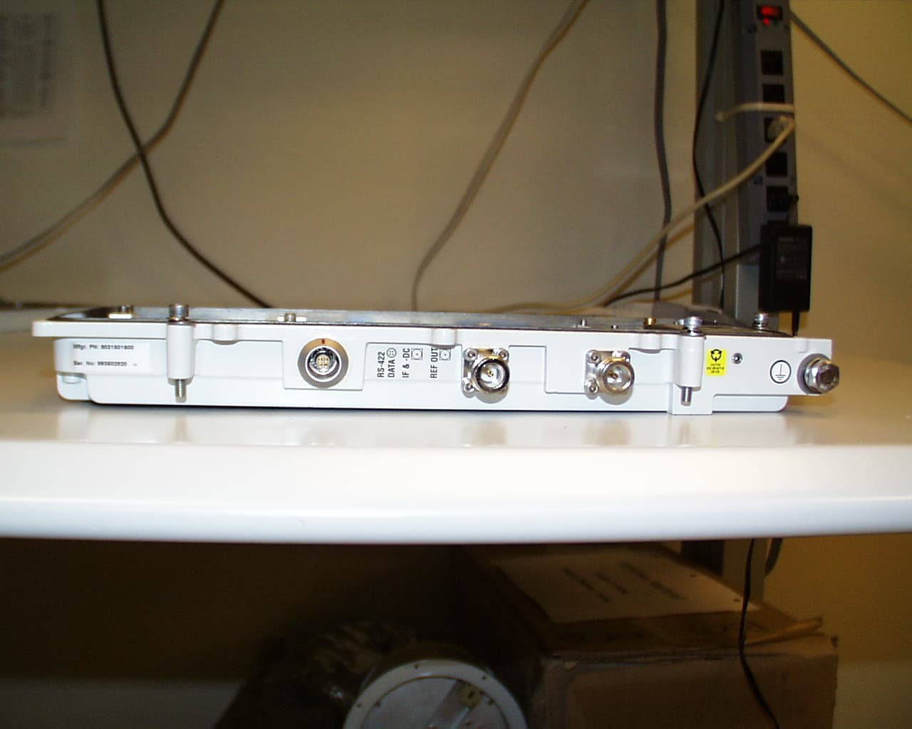
F9R31T28A04A22A
Sep 17, 2001Alcatel 7390 LMDS Broadband Wireless System - 31GHz
Equipment Class
TNB - Licensed Non-Broadcast Station Transmitter
F9R31T07A01A22B
Sep 16, 2001Alcatel 7390 LMDS Broadband Wireless System - 31GHz
Equipment Class
TNB - Licensed Non-Broadcast Station Transmitter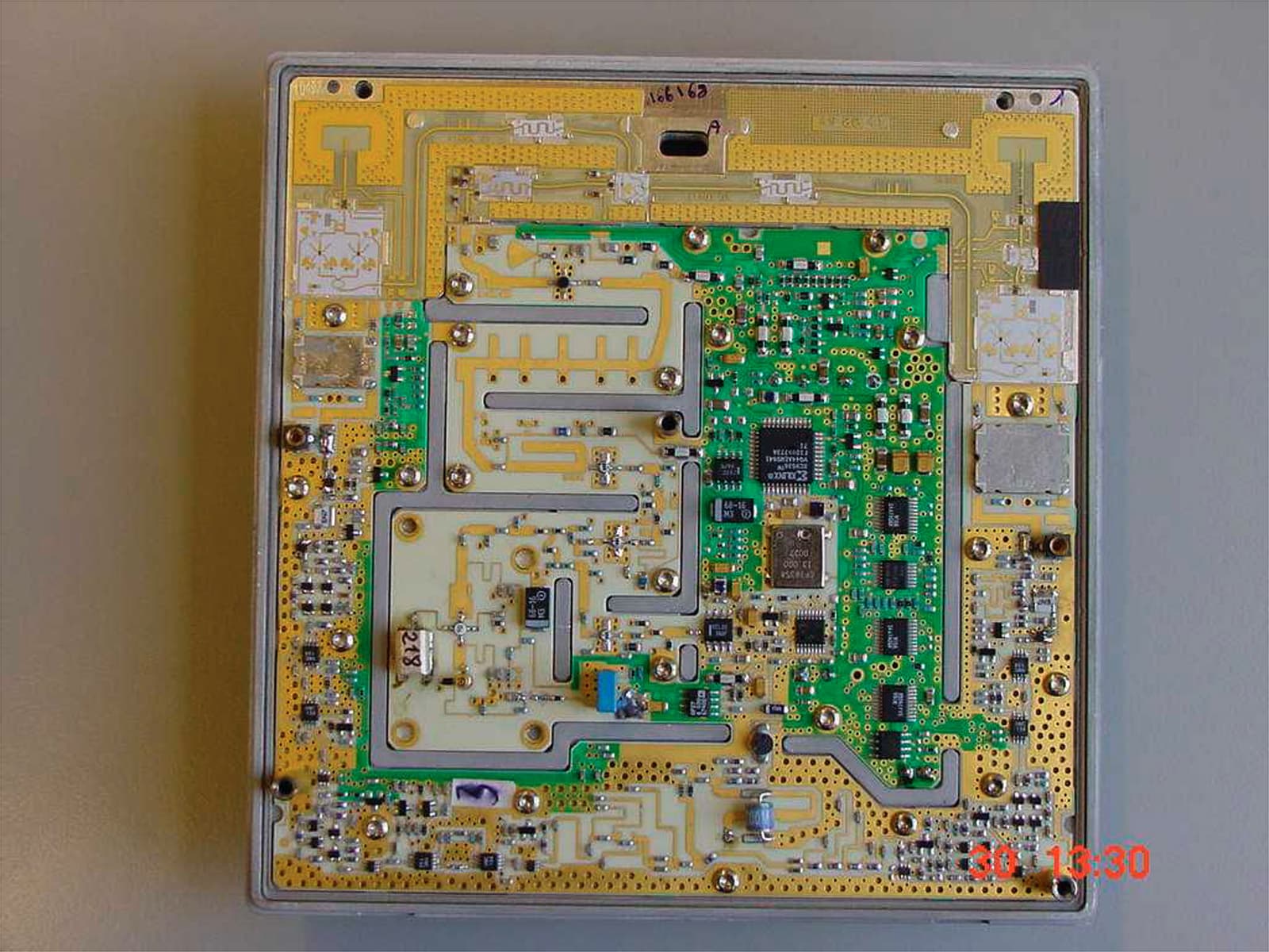
F9R24T07A01D22D
Aug 26, 20017390 24 GHz Co-Pol RT
Equipment Class
TNB - Licensed Non-Broadcast Station Transmitter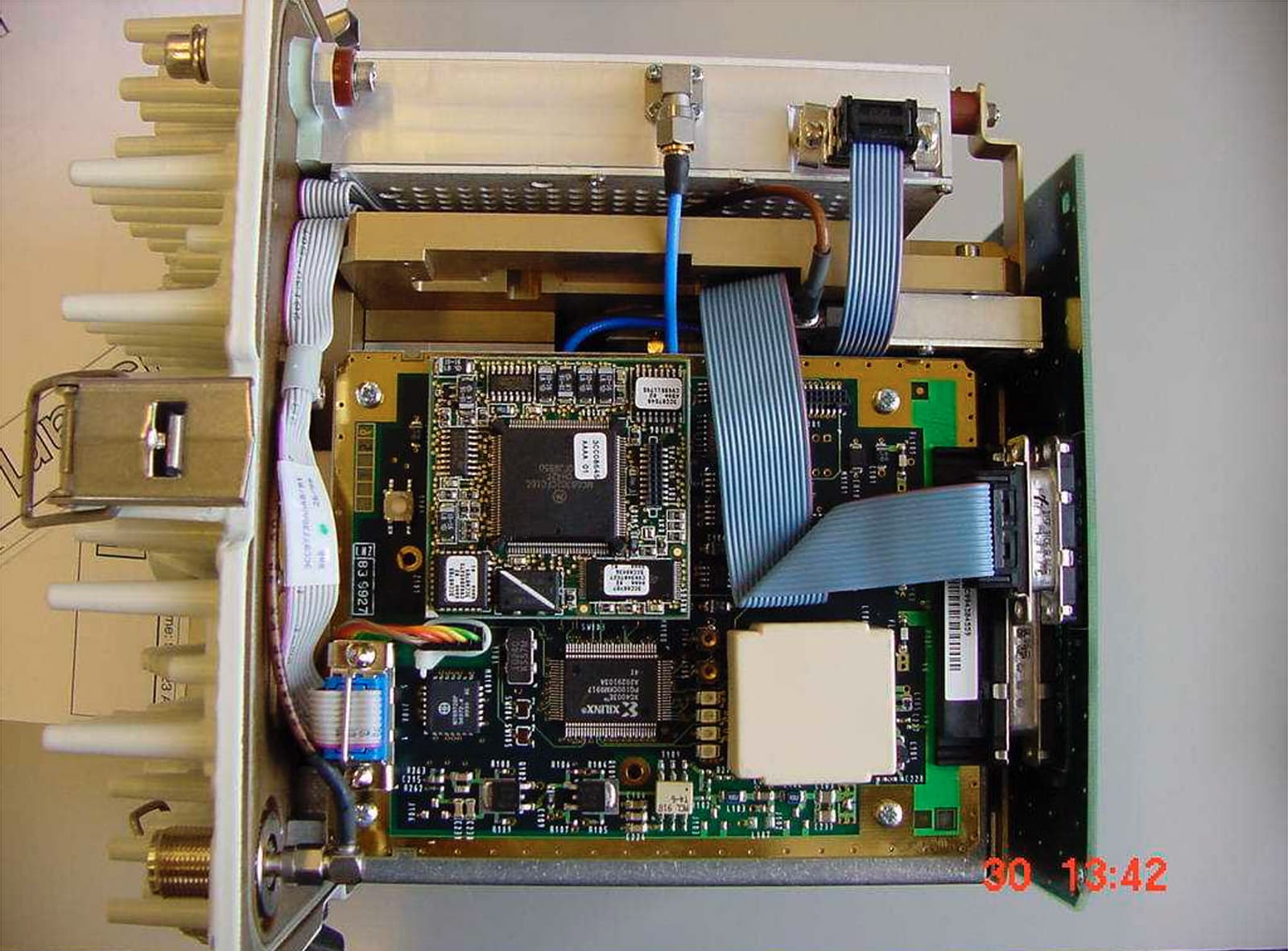
F9R24T28A01D22C
Aug 23, 20017390 24 GHz Co-Pol RBS
Equipment Class
TNB - Licensed Non-Broadcast Station Transmitter