FBIVB402051Auditory Assistance Listening Device
ClearOne, Inc.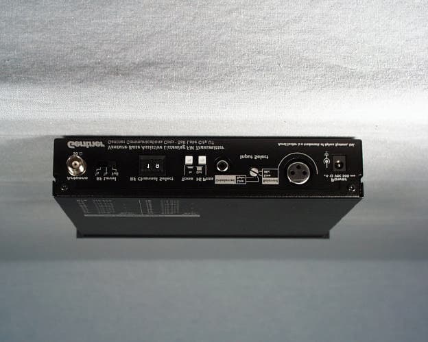
Click to zoom
Application Details
- Equipment Class
- TNB - Licensed Non-Broadcast Station Transmitter
- Date of Grant
- Feb 23, 1999
- Application Purpose
- Original Equipment
- Date of Application
- Dec 03, 1998
- Equipment Note
- Auditory Assistance Listening Device
- Frequency Range
- 216.02500000 - 216.97500000
- Company
- ClearOne, Inc.
- Country
- United States
Documents & Files
Document Text
Text extracted from the exhibit documents filed with the FCC. Open a document above to read the original.
Users Manual
COMMUNICATION CERTIFICATION LABORATORYTEST REPORT: 73-6637 FCC ID: FBIVB402051 Page 46 of 58 Exhibit 8 Exhibit 8: User’s Manual The user’s manual was sent as a separate pdf file. The compliance statement shown below is enclosed on pages 19-20 of the manual. FCC The Gentner Venture-Base Assistive Listening Transmitter complies with Part 95 of the FCC Rules. This devise may not interfere with TV reception or federal government radar, and must accept any interference received, including interference that may cause undesired operation. This transmitter is authorized by rule under the Low Power Radio Service (47 C.F.R. Part 95) and must not cause harmful interference to TV reception or United States Navy SPASUR installations. You do not need an FCC license to operate this transmitter. This transmitter may only be used to provide: auditory assistance to persons with disabilities, persons who require language translation, or persons in educational settings; health care services to the ill; law enforcement tracking services under agreement with a law enforcement agency; or automated maritime telecommunications system (AMTS) network control communications. Two-way voice communications and all other types of uses not mentioned above are expressly prohibited. Industry Canada This device complies with the requirements of the Department of Communications (DOC of Canada), as specified in document RSS-210. Operation is subject to the following two conditions: 1) This device may not cause harmful interference; 2) this device must accept any interference received, including interference that may cause any undesired operation. If TV channel 13 is used in the area, the installer of this system shall reduce or adjust the RF radiated power so that near- by TV channel 13 receivers do not receive radio interference from the system. (A test with a TV receiver equipped with “rabbit-ear antenna” and tuned to TV channel 13 should be conducted, at the perimeter of the user’s intended coverage area.)
Users Manual
Installation and Operations Manual Venture-Base Transmitter Gentner Communications Corporation Assistive Listening Systems © Copyright 1997 Gentner Communications Corporation. All rights reserved. No part of this manual may be reproduced in any form or by any means without written permission from Gentner Communications Corporation. Printed in the United States of America. Original version, 1/93. Gentner Communications Corporation reserves specification privileges. Information in this manual is subject to change without notice. Venture-Base Installation and Operations Manual September 1998 Manual Development: Bill Kilpack Copyright Information Venture-Base Transmitter Installation and Operations Manual Venture-Base Installation and Operations Manual Page iii Technical or Setup Assistance • Telephone: 800.945.7730 (USA) 801.975.7200 (worldwide) • Worldwide Web @ http://www.gentner.com Introduction1 Warranty Registration1 Product Description2 Accessories3 Front Panel Controls3 Back Panel Controls4 Installation5 Step 1 — Antenna Connection5 Step 2 — Audio Connection7 Step 3 — Apply Power8 Step 4 — Rack Mounting Option8 Operation8 Set Audio Level8 High Pass Switch9 Set the RF Level10 Receiver Tuning10 Reception Check10 Interference10 Frequency Chart11 Service12 Specifications12 Notice13 Warranty14 Contents Page iv Venture-Base Installation and Operations Manual Technical or Setup Assistance • Telephone: 800.945.7730 (USA) 801.975.7200 (worldwide) • Worldwide Web @ http://www.gentner.com List of Figures Figure 1. Venture-Base front panel controls ................................ 3 Figure 2. Venture-Base back panel controls ................................ 4 Figure 3. Remote antenna connection................................ 6 Figure 4. Amplifier connection................................ 7 Figure 5. Y-adaptor connection................................ 8 Figure 6. Venture-Base front panel controls ................................ 9 Figure 7. Venture-Base back panel controls .............................. 10 Venture-Base Installation and Operations Manual Page 1 Technical or Setup Assistance • Telephone: 800.945.7730 (USA) 801.975.7200 (worldwide) • Worldwide Web @ http://www.gentner.com Congratulations on purchasing the Venture-Base Assistive Listening Transmitter. The Venture-Base is the heart of the Gentner Assistive Listening System. As the most advanced device of its type, its design and manufacture result from research with audiologists, sound contractors, consultants and end users. It is designed to provide the highest possible audio and RF performance. The Venture- Base is reliable, easy to use and provides quality performance. The Venture-Base has audio inputs for audio sources, ranging from microphone to loudspeaker (balanced and unbalanced). It contains a series of audio processors to shape the input dynamics and frequency response. This produces clear sound for the hearing impaired, with minimal adjustment. The RF section is crystal-controlled for long-term stability, and uses digital frequency-synthesizer circuitry, allowing the transmitter to be instantly set to 19 FCC-approved ALS channels. If you need additional information on how to install, set up or operate your Venture-Base, please contact us at Gentner Communications at the location noted below. We welcome and encourage your comments so we can continue to improve our products and better serve your communication needs. Gentner Communications Corporation 1825 Research Way, Salt Lake City, Utah 84119 TEL: Worldwide 801.975.7200 In U.S.A. 800.945.7730 FAX: Worldwide 801.977.0087 In U.S.A. 800.933.5107 FAX-On-Demand 24-Hour Information Service 800.695.8110 FAX-On-Demand International line 801.974.3661 Worldwide Web Page @ http:\\www.gentner.com Warranty Registration Please register your Venture-Base online by visiting Technical Support at the Gentner Worldwide Web Site. Introduction Page 2 Venture-Base Installation and Operations Manual Technical or Setup Assistance • Telephone: 800.945.7730 (USA) 801.975.7200 (worldwide) • Worldwide Web @ http://www.gentner.com Making sound clearer for the hearing impaired requires more than just making it louder. The needs of the hearing impaired differ from those with normal hearing. Audio processing is needed to reshape the sound. The most common impairments are reduced sensitivity and dynamic range, and loss of high frequencies. Many of the audio sources have extremely high dynamic range — often difficult to hear under optimal circumstances. The Venture Base’s audio processing is similar to that used at a commercial radio station. Automatic gain control (AGC) controls the long-term levels, equalizing different types of program material. This compensates for variations in level. The audio is tied to the AGC circuit, so incoming audio is always controlled, greatly reducing distortion. Audio passes through a split-band compressor, reducing the signal’s dynamics, making the sound not only louder but more intelligible. Normally, available compression is very limited, since too much compression creates a dull, muffled sound. To prevent this, the Venture-Base splits the audio into high and low bands. It then processes them separately, so each band receives the correct amount of compression. This allows more compression overall, amplifying sound without dullness — and without noticing the compression. After compression, the sound is fed to the patented Aphex Aural Exciter® circuit. This process has been used in the recording and broadcast industries for decades. Aphex processing creates an increase in perceived brightness for the listener. A final signal limiter is used to provide an absolute audio peak level so the FM signal can never be over- modulated (which causes distortion). People with or without hearing impairment appreciate this sophisticated processing, with its clear sound and improved intelligibility. Product Description Venture-Base Installation and Operations Manual Page 3 Technical or…
Text truncated - open the document above for the full version.
Block Diagram
COMMUNICATION CERTIFICATION LABORATORYTEST REPORT: 73-6637 FCC ID: FBIVB402051 Page 6 of 58 Exhibit 4 Exhibit 4: Block Diagrams
Cover Letter(s)
COMMUNICATION CERTIFICATION LABORATORYTEST REPORT: 73-6637 FCC ID: FBIVB402051 Page 58 of 58 Exhibit 13 Exhibit 13: Cover Letters December 3, 1998 FEDERAL COMMUNICATIONS COMMISSION Equipment Authorization Division 7435 Oakland Mills Road Columbia, MD 21046 To Whom It May Concern: Enclosed is a FCC Part 95, Certification application for the Gentner Communications Corporation Model Venture-Base, FCC ID: FBIVB402051. Please let me know if I can be of further assistance. Sincerely yours, COMMUNICATION CERTIFICATION LABORATORY Joseph W. Jackson V.P. Marketing
External Photos
COMMUNICATION CERTIFICATION LABORATORYTEST REPORT: 73-6637 FCC ID: FBIVB402051 Page 4 of 58 Exhibit 3 Exhibit 3: Photographs of Overall Appearance Front View of the Venture-Base COMMUNICATION CERTIFICATION LABORATORYTEST REPORT: 73-6637 FCC ID: FBIVB402051 Page 5 of 58 Exhibit 3 Back View of the Venture-Base
ID Label/Location Info
COMMUNICATION CERTIFICATION LABORATORYTEST REPORT: 73-6637 FCC ID: FBIVB402051 Page 1 of 58 Exhibit 1 Exhibit 1: FCC ID Label Equipment Identification Label In accordance with the requirements of Sections 95.1017(a), 2.925 and 2.926 of the FCC Rules, the following information will be permanently affixed to the Gentner Communications Corporation Model Venture-Base as shown in the sketch below. Due to the size of the equipment, the label contains only the FCC ID only, and the compliance statement is provided on pages 19-20 of the User’s manual. COMMUNICATION CERTIFICATION LABORATORYTEST REPORT: 73-6637 FCC ID: FBIVB402051 Page 2 of 58 Exhibit 1 Sketch of the back exterior view showing the label placement.
Internal Photos
COMMUNICATION CERTIFICATION LABORATORYTEST REPORT: 73-6637 FCC ID: FBIVB402051 Page 47 of 58 Exhibit 9 Exhibit 9: Internal Photographs Inside view of the Venture-Base COMMUNICATION CERTIFICATION LABORATORYTEST REPORT: 73-6637 FCC ID: FBIVB402051 Page 48 of 58 Exhibit 9 Component Side of the Venture-Base COMMUNICATION CERTIFICATION LABORATORYTEST REPORT: 73-6637 FCC ID: FBIVB402051 Page 49 of 58 Exhibit 9 Solder Side of the Venture-Base
Operational Description
COMMUNICATION CERTIFICATION LABORATORYTEST REPORT: 73-6637 FCC ID: FBIVB402051 Page 57 of 58 Exhibit 12 Exhibit 12: Operational Description Emission Designator First Symbol – type of modulation of the main carrier. The modulation of the VCO is linearly FM modulated; therefore, the first symbol = F Second Symbol – nature of signal modulating the main carrier. The signal consists of a single channel containing analog information; therefore, the second symbol = 3 Third Symbol – type of information to be transmitted. The information transmitted is analog voice; therefore, the third symbol = E The bandwidth of the device was measured to be 24.6 kHz; therefore, the emission designator = 25K0F3E.
Operational Description
COMMUNICATION CERTIFICATION LABORATORYTEST REPORT: 73-6637 FCC ID: FBIVB402051 Page 57 of 58 Exhibit 12 Exhibit 12: Operational Description Emission Designator First Symbol – type of modulation of the main carrier. The modulation of the VCO is linearly FM modulated; therefore, the first symbol = F Second Symbol – nature of signal modulating the main carrier. The signal consists of a single channel containing analog information; therefore, the second symbol = 3 Third Symbol – type of information to be transmitted. The information transmitted is analog voice; therefore, the third symbol = E The bandwidth of the device was measured to be 24.6 kHz; therefore, the emission designator = 25K0F3E.
Parts List/Tune Up Info
COMMUNICATION CERTIFICATION LABORATORYTEST REPORT: 73-6637 FCC ID: FBIVB402051 Page 50 of 58 Exhibit 10 Exhibit 10: Information Required for Certification COMMUNICATION CERTIFICATION LABORATORYTEST REPORT: 73-6637 FCC ID: FBIVB402051 Page 51 of 58 Exhibit 10 COMMUNICATION CERTIFICATION LABORATORYTEST REPORT: 73-6637 FCC ID: FBIVB402051 Page 52 of 58 Exhibit 10 COMMUNICATION CERTIFICATION LABORATORYTEST REPORT: 73-6637 FCC ID: FBIVB402051 Page 53 of 58 Exhibit 10 Tune up Procedures SCOPE 1This procedure details the process for testing the Venture Base Transmitter. 2 APPLICABLE DOCUMENTS/SPECIFICATIONS 2.1N/A 3FORMS 3.1Testing Log 3.2Failed Product Disposition Log 4SPECIAL TOOLS 4.11 - HP 8901A Modulation Analyzer 4.21 - 1701A Distortion Measurement System 4.31 - ALS Venture Receiver 5 PROCEDURE 5.1 Output Frequency Test 5.1.1 Open the Venture Base case lid to expose components. 5.1.2 Turn on the HP 8901A Modulation Analyzer and push the Frequency Measurement button ON. 5.1.3 Connect the antenna output of the Venture Base to HP 8901A Modulation Analyzer. 5.1.4 Select channel 01 on the Venture Base. 5.1.5 Provide power to the Venture Base. 5.1.6 Depress the power switch on the front of the Venture Base. 5.1.7 Verify the POWER LED and RF LED illuminate. 5.1.8 On the front and back of the Venture Base, verify all of the switches are in the out position. 5.1.9 On the back of the Venture Base, verify the input selector knob is turned to the MIC position. 5.1.10 The frequency measurement on the analyzer should be 216.025MHz +/-1kHz. If necessary, adjust C57 trimmer on the main circuit board until output frequency is correct (216,024,000 – 216,026,000). 5.1.11 Turn the Venture Base channel selector to channel 19. 5.1.12 Verify that output frequency 216.975MHz +/- 1kHz (216,974,000 –216,976,000). 5.1.13 Adjust the trimmer (if necessary). 5.2 Output Level Test 5.2.1 On HP 8901A Modulation Analyzer, push RF level measurement button. COMMUNICATION CERTIFICATION LABORATORYTEST REPORT: 73-6637 FCC ID: FBIVB402051 Page 54 of 58 Exhibit 10 5.2.2 On the back of the Venture Base, set RF level setting to FULL. 5.2.3 Set the Venture Base to channel 01. 5.2.4 The power measurement on the analyzer should be 100 mW +0, -10%. If necessary, adjust potentiometer VR9 (full power). 5.2.5 On the back of the Venture Base, set RF level setting to HALF. 5.2.6 Adjust potentiometer VR11 (one-half power) to 50.0mW +/-10%. 5.2.7 On the back of the Venture Base, set RF level setting to QUARTER. 5.2.8 Adjust potentiometer VR10 (one-quarter power) to 25.0mW +/-10%. 5.3 RF Modulation Test 5.3.1 Set VENTURE BASE Transmitter for balanced line level input on channel 01. 5.3.2 On the back, set TONE and HI-PASS switched to the OFF position. 5.3.3 On the front panel, set the APHEX switch to OFF. 5.3.4 Set AUDIO INPUT and PROCESS level trimmers to maximum (216.025 MHz). 5.3.5 Connect a 1kHz, 0dBm signal to the balanced line- level XLR input. 5.3.6 If necessary, adjust VR4 for 30kHz +/- 4kHz of deviation. 5.3.7 Set APHEX switch to ON. 5.3.8 If necessary, adjust VR7 for 36kHz +/- 3kHz of deviation. 5.3.9 Turn APHEX OFF. 5.3.10 Adjust VR8 until the HIGH front-panel indicator just begins to illuminate. The HIGH LED should extinguish when the AUDIO LEVEL front-panel control it rotated back to the 3 o’clock position. 5.3.11 Disconnect the 1kHz test signal and turn ON the internal test tone. 5.3.12 Change the broadcast channel to channel 19 (216.975 MHz). 5.3.13 If necessary, adjust VR5 for tone of 400Hz and minimum THD. 5.3.14 If tone is measured by adjusting VR6 to 30kHz then DO NOT adjust VR5. 5.3.15 Adjust VR6 for 30kHz +/-3kHz deviation. 5.3.16 If adjustment cannot be made to 30kHz then turn VR5 one quarter turn and adjust VR6 to the proper setting. COMMUNICATION CERTIFICATION LABORATORYTEST REPORT: 73-6637 FCC ID: FBIVB402051 Page 55 of 58 Exhibit 10 5.4 System Test 5.4.1 Press the TONE button to the OFF position. 5.4.2 Switch to unbalanced line position. 5.4.3 Plug in audio RCA jacks. 5.4.4 Plug in the headphone-to-headphone jack on the VENTURE BASE’s front panel. 5.4.5 Listen to the audio as generated by the audio source. Verify the sound quality. 5.4.6 Turn dials on panel and verify that there is no unwanted noise. 5.4.7 Push the APHEX button in and out to verify the increase in power/volume boost. 5.5 Pass/Fail Specification 5.5.1 If the product passes test specifications, complete assembly of product, stamp with appropriate QC stamp and enter on test log form. 5.5.2 If the product fails to meet test specifications, follow procedures for failed product. 6 RECORDS/MAINTENANCE RESPONSIBILITY 6.1 This procedure is part of the Manufacturing Engineering Test Procedures, Sub Manual 03 and is to be maintained by the Manufacturing Engineering department.
Schematics
COMMUNICATION CERTIFICATION LABORATORYTEST REPORT: 73-6637 FCC ID: FBIVB402051 Page 7 of 58 Exhibit 5 Exhibit 5: Schematic Diagrams COMMUNICATION CERTIFICATION LABORATORYTEST REPORT: 73-6637 FCC ID: FBIVB402051 Page 8 of 58 Exhibit 5
Test Report
COMMUNICATION CERTIFICATION LABORATORYTEST REPORT: 73-6637 FCC ID: FBIVB402051 Page 9 of 58 Exhibit 6 Exhibit 6: Test Report TEST REPORT FROM: COMMUNICATION CERTIFICATION LABORATORY 1940 W. Alexander Street Salt Lake City, Utah 84119-2039 Type of Report: Certification TEST OF: Venture-Base FCC ID: FBIVB402051 To FCC PART 95, Subparts E and G Test Report Serial No: 73-6637 Applicant: Gentner Communications Corporation 1825 Research Way Salt Lake City, UT 84119 Date(s) of Test: October 12 – 23, 1998 Issue Date: December 3, 1998 Equipment Receipt Date: September 24, 1998 COMMUNICATION CERTIFICATION LABORATORYTEST REPORT: 73-6637 FCC ID: FBIVB402051 Page 10 of 58 Exhibit 6 CERTIFICATION OF ENGINEERING REPORT This report has been prepared by Communication Certification Laboratory to determine compliance of the device described below with the notification requirements of FCC Part 95, Subparts E and G. This report may be reproduced in full, partial reproduction may only be made with the written consent of the laboratory. The results in this report apply only to the sample tested. -Applicant:Gentner Communications Corporation - Manufacturer:Gentner Communications Corporation -Brand Name:GENTNER -Model Number:Venture-Base -FCC ID:FBIVB402051 On this 3 rd day of December 1998, I, individually, and for Communication Certification Laboratory, certify that the statements made in this engineering report are true, complete, and correct to the best of my knowledge, and are made in good faith. Although NVLAP has recognized that the Communication Certification Laboratory EMC testing facilities are in good standing, NVLAP does not endorse the product described in this report. COMMUNICATION CERTIFICATION LABORATORY Checked by: Roger J. Midgley EMC Engineering Manager Tested by: Kirk P. Thomas EMC Technician COMMUNICATION CERTIFICATION LABORATORYTEST REPORT: 73-6637 FCC ID: FBIVB402051 Page 11 of 58 Exhibit 6 SECTION 1.0 CLIENT INFORMATION 1.1 Client Information: Company Name: Gentner Communications Corporation 1825 Research Way Salt Lake City, UT 84119 Contact Name:Steve Townsend Title:Manufacturing Engineering Manager COMMUNICATION CERTIFICATION LABORATORYTEST REPORT: 73-6637 FCC ID: FBIVB402051 Page 12 of 58 Exhibit 6 SECTION 2.0 EQUIPMENT UNDER TEST (EUT) 2.1 Identification of EUT: Trade Name:GENTNER Model Name or Number:Venture-Base Serial Number:N/A Options Fitted:N/A Country of Manufacture:Taiwan, R.O.C. 2.2 Description of EUT: The Venture-Base is a nineteen channel; FM transmitter used as a Low Power Radio Service (LPRS) for auditory assistance, language translation or education. It operates in the frequency range of 216 MHz to 217 MHz. The Venture-base allows the user to select nineteen different channels with an external selector wheel. The output level can be adjusted to full power, ½ power or ¼ power via a switch on the back of the unit. The Venture-base is equipped with two audio inputs on the back of the unit for connection to audio sources, ranging from microphone to loudspeaker (balanced and unbalanced). 2.3 Modification Incorporated/Special Accessories on EUT: There were no modifications or special accessories required to comply with the specification. COMMUNICATION CERTIFICATION LABORATORYTEST REPORT: 73-6637 FCC ID: FBIVB402051 Page 13 of 58 Exhibit 6 SECTION 3.0 TEST SPECIFICATION, METHODS & PROCEDURES 3.1 Test Specification: Title:FCC PART 95, Subparts E and G (47 CFR 95). Low Power Radio Service (LPRS). Purpose of Test: The tests were performed to demonstrate Initial compliance. 3.2 Methods & Procedures (Applicable to the Venture-Base): 3.2.1 '' 95.605 Certification Procedures Any entity may request certification for its transmitter when the transmitter is used in the GMRS, R/C, CB, IVDS, FRS or LPRS following the procedures in Part 2 of this chapter. 3.2.2 '' 95.629 LPRS Transmitter Frequencies (a) LPRS transmitters may operate on any frequency listed in paragraphs (b), (c), and (d) of this section. Channels 19, 20, 50 and 151-160 are available exclusively for law enforcement tracking purposes. AMTS transmissions are limited to the 216.750-217.000 MHz band for low power point-to-point network control communications by AMTS coast stations. Other AMTS transmissions in the 216-217 MHz band are prohibited. (c) Extra band channels. (i) The following table indicates extra band frequencies. The channel bandwidth is 50 kHz. Channel No.Center frequency (MHz) 41216.025 42 216.075 43 216.125 44 216.175 45 216.225 46 216.275 47 216.325 48 216.375 49 216.425 50 216.475 COMMUNICATION CERTIFICATION LABORATORYTEST REPORT: 73-6637 FCC ID: FBIVB402051 Page 14 of 58 Exhibit 6 51 216.525 52 216.575 53 216.625 54 216.675 55 216.725 56 216.775 57 216.825 58 216.875 59 216.925 60 216.975 (ii) LPRS transmitters operating on extra band channels must be maintained within a frequency stability of 50 parts per million. 3.2.3 '' 95.631 Emission Types (g) An LPRS station may transmit any emission type appropriate for communication in this service. Two-way communication, however, are prohibited. 3.2.4 '' 95.633 Emission Bandwidth (d) For transmitters in the LPRS: (3) The channel bandwidth for extra band frequencies is 50 kHz. 3.2.5 '' 95.635 Unwanted Radiation (c) For transmitters designed to operate in the LPRS, emissions shall be attenuated in accordance with the following. (2) Emissions for LPRS transmitters operating on extra band channels (50 kHz) shall be attenuated below the unmodulated carrier in accordance with the following: (i) Emissions 25 kHz to 35 kHz from the channel center frequency: at least 30 dB. (ii) Emission more than 35 kHz away from the channel center frequency: at least 43 + 10log(carrier power in watts) dB. 3.2.6 '' 95.639 Maximum Transmitter Power (e) The maximum transmitter output power authorized for LPRS stations is 100 mW. COMMUNICATION CERTIFICATION LABORATORYTEST REPORT: 73-6637 FCC ID: FBIVB402051 Page 15 of 58 Exhibit 6 3.2.7 '' 95.649 Power Capability No CB, R/C, LPRS transmitter, …
Text truncated - open the document above for the full version.
Test Setup Photos
COMMUNICATION CERTIFICATION LABORATORYTEST REPORT: 73-6637 FCC ID: FBIVB402051 Page 44 of 58 Exhibit 7 Exhibit 7: Test Set-Up Photographs Front view of worst case radiated emissions COMMUNICATION CERTIFICATION LABORATORYTEST REPORT: 73-6637 FCC ID: FBIVB402051 Page 45 of 58 Exhibit 7 Back view of worst case radiated emissions
Contact Information
Applicant
Derek Graham(Sr. V.P. of Research and Development)
Technical Contact
Communication Certification LaboratoryRoger J Midgley
[email protected](801) 972-6146
1940 W. Alexander Street · Salt Lake City, Utah · United States
Test Firm
Communication Certification Lab.Scott Earl
Technical Specifications
| # | Rule Parts | Frequency Range | Power Output | Emission | Tolerance |
|---|---|---|---|---|---|
| 1 | 95G | 216.025 MHz - 216.975 MHz | 100.00 mW | 25K0F3E | 50.0000000000 ppm |
Other Applications from ClearOne, Inc.
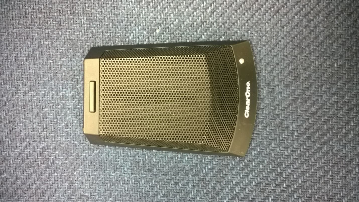
FBITABLETOP
Jan 01, 2015TABLE TOP WIRELESS MICROPHONE
Equipment Class
TBC - Licensed Broadcast Station Transmitter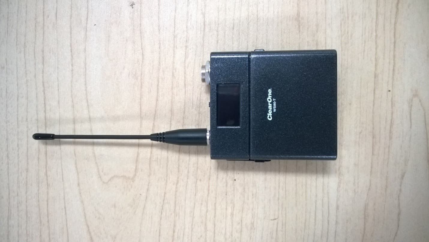
FBIBELTPACK
Dec 29, 2014BELTPACK WIRELESS MICROPHONE
Equipment Class
TBC - Licensed Broadcast Station Transmitter
FBIGOOSENECK
Dec 29, 2014GOOSENECK WIRELESS MICROPHONE
Equipment Class
TBC - Licensed Broadcast Station Transmitter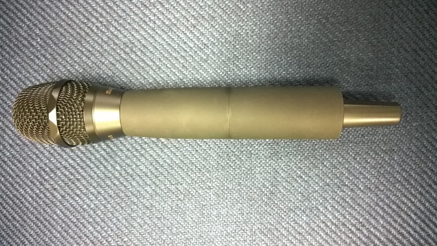
FBIHANDHELDMIC
Dec 29, 2014HANDHELD WIRELESS MICROPHONE
Equipment Class
TBF - Licensed Broadcast Transmitter Held to Face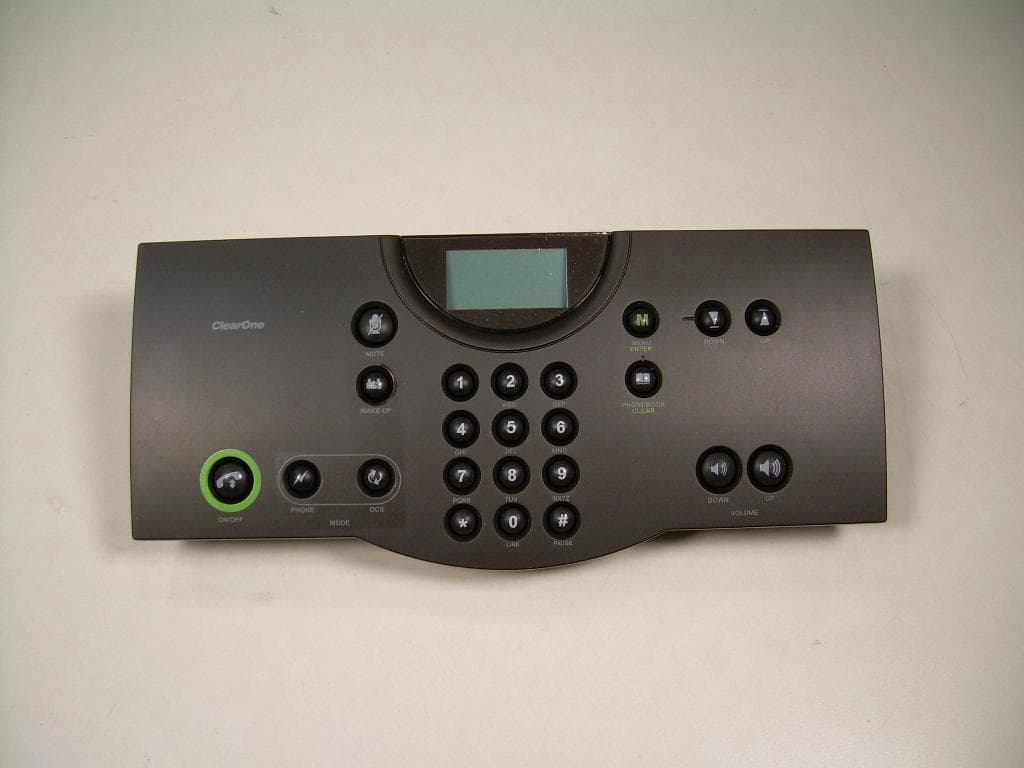
FBIDIALER
May 26, 2010Interact DIALER-W
Equipment Class
DTS - Digital Transmission System