FBIVE402061Auditory Assistance Tranmsmitter
ClearOne, Inc.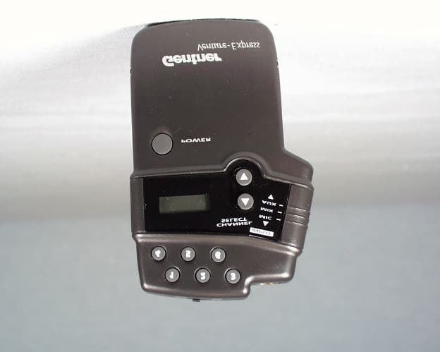
Click to zoom
Application Details
- Equipment Class
- TNB - Licensed Non-Broadcast Station Transmitter
- Date of Grant
- Mar 29, 1999
- Application Purpose
- Original Equipment
- Date of Application
- Dec 20, 1998
- Equipment Note
- Auditory Assistance Tranmsmitter
- Frequency Range
- 216.00000000 - 217.00000000
- Company
- ClearOne, Inc.
- Country
- United States
Documents & Files
Document Text
Text extracted from the exhibit documents filed with the FCC. Open a document above to read the original.
Users Manual
Venture-Express Transmitter User’s Guide Assistive Listening Systems Page ii Venture-Express User’s Guide For Technical Assistance Dial: 800-283-5936 or 801-974-3760 © Copyright 1998 by Gentner Communications Corporation. All rights reserved. No part of this manual may be reproduced in any form or by any means without written permission from Gentner Communications Corporation. Printed in the United States of America. Original version, 1/96. Gentner Communications Corporation reserves specification privileges. Information in this manual is subject to change without notice. Venture-Express User’s Guide, September 1998 Interference Problems8 Specifications9 Notice10 Warranty12 Contents Copyright Information Introduction1 Features and Controls1 Audio Processing1 Controls3 Setup3 Antenna/Microphone4 Install Batteries5 Select Audio Input6 Operation6 Powering the Venture-Express6 Selecting a Channel6 Setting Memory Channels6 Frequency Chart7 Check the System8 Using the Mix Function8 Low-Battery Indication8 For Technical Assistance Dial: 800-283-5936 or 801-974-3760 Venture-Express User’s Guide Page 1 The Venture-Express portable transmitter results from years of surveying audiologists, sound contractors, consultants and end users. It is designed to provide every feature and function with the highest possible audio/RF performance and reliable operation while remaining affordable and easy to use. The Venture-Express has audio inputs for both microphone and line (i.e. tape or CD player). The two sources can also be mixed. An audio processor shapes the input audio dynamics and frequency response to produce a signal with maximum intelligibility and minimal operator adjustment. The RF section is crystal-controlled for stability. Its digital frequency-synthesizer circuitry sets the transmitter to 19 of the FCC-approved Assistive Listening Band’s channels. Six memory channels can recall frequent-use channels. Audio Processing To make transmitted sound intelligible to the hearing impaired, making it louder is not enough. The needs of the hearing impaired differ greatly from those with normal hearing. The most common impairments are reduced sensitivity and dynamic Introduction Features and Controls Page 2 Venture-Express User’s Guide For Technical Assistance Dial: 800-283-5936 or 801-974-3760 range, and loss of high frequencies. The Venture-Express uses a system of program-dependent AGC with a proprietary frequency-shaping system to control dynamics and maximize voice intelligibility. This results in a clear, loud sound, and eliminates the need to constantly raise and lower receiver volume. Figure 1. Venture-Express front panel For Technical Assistance Dial: 800-283-5936 or 801-974-3760 Venture-Express User’s Guide Page 3 Controls Power: Turns on/off the power to the Venture-Express transmitter Channel Select: Allow the user to scroll up or down through the 19 preprogrammed channels Memory Recall Buttons: May be programmed to any of the 19 channels for instant recall Display: LCD display shows the channel the Venture-Express is currently using. If tuned manually, the channel will be prefixed by a C (example: C-07). If tuned using a memorized channel, the channel will be prefixed by the memory-button number (example: 4-07). Input Selector: Allows the user to broadcast the audio input from a microphone, a line source or a mix of both Line Input Jack: A standard 1/8-inch/3.5mm jack for an outside audio source (i.e. tape or CD player) Mic Mute Switch: Allows the user to mute the mic audio input, not the auxiliary audio input Mic Input Jack: A mini XLR-type professional connector with a locking action to prevent the mic plug from being Figure 2. Venture-Express top view Page 4 Venture-Express User’s Guide For Technical Assistance Dial: 800-283-5936 or 801-974-3760 Figure 3. Venture-Express back view accidentally pulled out Belt Clip: Securely attaches the Venture-Express to the user’s belt for portable operation Battery Door: Venture-Express uses two AA batteries (alkaline or rechargeable Ni-Cad) Antenna/Microphone The Venture-Express antenna is 2/3 internal to the PTX unit, 1/3 in the microphone cord. With this in mind, it is recommended, although not required, that the microphone be attached before use and that the cord is as fully extended as possible during use. Setup For Technical Assistance Dial: 800-283-5936 or 801-974-3760 Venture-Express User’s Guide Page 5 Also, ensure that you maintain line-of-sight contact with the receivers, so walls with large amounts of wiring, metal studs or concrete do not block or reduce the signal. Please Note: Any RF system is susceptible to “dropouts,” where reduced RF energy caused by reflections and cancellations results in a noisy signal. If this happens, try moving the transmitter or receiver around until the signal clears. Sometimes, even a few inches can cause a dramatic difference in performance. Install Batteries The Venture-Express uses two AA batteries. For best results, we recommend alkaline types with a minimum of 600 mAHrs each of power. To install the batteries, slide the battery door down and place the two batteries as indicated in the battery compartment. The Venture-Express can also use the Gentner BC-10A recharging system and Ni-Cad rechargeable batteries. Caution: Never use standard Alkaline batteries in a recharger. The batteries can explode or leak, severely damaging the transmitter and charger. Page 6 Venture-Express User’s Guide For Technical Assistance Dial: 800-283-5936 or 801-974-3760 Select Audio Input If a microphone will be used (normal operation), select the MIC position on the input selector. To feed audio from an outside source, select the LINE position and insert the audio cable from the external source into the line jack. For proper microphone operation, ensure the MUTE switch is positioned in the MIC on position. Powering the Venture-Express Press the POWER button. The LCD display will come on, indicating which of the 19 channels is tune…
Text truncated - open the document above for the full version.
Block Diagram
COMMUNICATION CERTIFICATION LABORATORYTEST REPORT: 73-6687 FCC ID: FBIVE402061 Page 6 of 57 Exhibit 4 Exhibit 4: Block Diagrams
External Photos
COMMUNICATION CERTIFICATION LABORATORYTEST REPORT: 73-6687 FCC ID: FBIVE402061 Page 4 of 57 Exhibit 3 Exhibit 3: Photographs of Overall Appearance Front View of the Venture-Express COMMUNICATION CERTIFICATION LABORATORYTEST REPORT: 73-6687 FCC ID: FBIVE402061 Page 5 of 57 Exhibit 3 Back View of the Venture-Express
ID Label/Location Info
COMMUNICATION CERTIFICATION LABORATORYTEST REPORT: 73-6687 FCC ID: FBIVE402061 Page 1 of 57 Exhibit 1 Exhibit 1: FCC ID Label Equipment Identification Label In accordance with the requirements of Sections 95.1017(a), 2.925 and 2.926 of the FCC Rules, the following information will be permanently affixed to the Gentner Communications Corporation Model Venture-Express as shown in the sketch below. Due to the size of the equipment, the label contains only the FCC ID only, and the compliance statement is provided on pages 12-13 of the User’s manual. Assistive Listening Transmitter Made in Taiwan CANADA: ??? ??? ??? Model— Venture-Express FCC ID: FBIVE402061 44.70 mm 7 . 8 7 m m COMMUNICATION CERTIFICATION LABORATORYTEST REPORT: 73-6687 FCC ID: FBIVE402061 Page 2 of 57 Exhibit 1 Sketch of the back exterior view showing the label placement.
Internal Photos
COMMUNICATION CERTIFICATION LABORATORYTEST REPORT: 73-6687 FCC ID: FBIVE402061 Page 45 of 57 Exhibit 9 Exhibit 9: Internal Photographs Inside view of the Venture-Express (Showing both boards) COMMUNICATION CERTIFICATION LABORATORYTEST REPORT: 73-6687 FCC ID: FBIVE402061 Page 46 of 57 Exhibit 9 Side A of the Venture-Express (Main board) COMMUNICATION CERTIFICATION LABORATORYTEST REPORT: 73-6687 FCC ID: FBIVE402061 Page 47 of 57 Exhibit 9 Side B of the Venture-Express (Main board) COMMUNICATION CERTIFICATION LABORATORYTEST REPORT: 73-6687 FCC ID: FBIVE402061 Page 48 of 57 Exhibit 9 Side A of the Venture-Express (CPU board) COMMUNICATION CERTIFICATION LABORATORYTEST REPORT: 73-6687 FCC ID: FBIVE402061 Page 49 of 57 Exhibit 9 Side B of the Venture-Express (CPU board)
Operational Description
COMMUNICATION CERTIFICATION LABORATORYTEST REPORT: 73-6687 FCC ID: FBIVE402061 Page 56 of 57 Exhibit 12 Exhibit 12: Operational Description Emission Designator First Symbol – type of modulation of the main carrier. The modulation of the VCO is linearly FM modulated; therefore, the first symbol = F Second Symbol – nature of signal modulating the main carrier. The signal consists of a single channel containing analog information; therefore, the second symbol = 3 Third Symbol – type of information to be transmitted. The information transmitted is analog voice; therefore, the third symbol = E The bandwidth of the device was measured to be 24.6 kHz; therefore, the emission designator = 25K0F3E.
Parts List/Tune Up Info
COMMUNICATION CERTIFICATION LABORATORYTEST REPORT: 73-6687 FCC ID: FBIVE402061 Page 50 of 57 Exhibit 10 Exhibit 10: Information Required for Certification COMMUNICATION CERTIFICATION LABORATORYTEST REPORT: 73-6687 FCC ID: FBIVE402061 Page 51 of 57 Exhibit 10 COMMUNICATION CERTIFICATION LABORATORYTEST REPORT: 73-6687 FCC ID: FBIVE402061 Page 52 of 57 Exhibit 10 Tune up Procedures 1 SCOPE 1.1 This procedure details the process for testing the Venture Express Transmitter. 2 APPLICABLE DOCUMENTS/SPECIFICATIONS 2.1 N/A 3 FORMS 3.1 Testing Log 3.2 Failed Product Disposition Log 4 SPECIAL TOOLS 4.1 1 - HP3561A Dynamic Signal Analyzer 4.2 1 - IFR Modulated Signal Generator 4.3 1 - 1710 Distortion Measurement System 4.4 2 - Fully Charged AA-Sized Batteries 5 PROCEDURE 5.1 Test Setup 5.1.1 Verify packaging and labeling • Properly packaged with all components (plastic screwdriver, microphone, VENTURE EXPRESS and manual) • Properly labeled (product and packaging) with corresponding serial numbers 5.1.2 Install batteries and turn unit ON 5.2 Preset Testing 5.2.1 Verify presets • Button 1, Channel 01 • Button 2, Channel 04 • Button 3, Channel 07 • Button 4, Channel 10 • Button 5, Channel 13 • Button 6, Channel 17 5.3 Verify broadcast frequency of Channel 01. 5.3.1 Select 216.025 MHz on the thumbwheel of IFR Modulation System and select Channel 1 on the VENTURE EXPRESS by pressing button 1 and the DOWN arrow until Channel 1 is displayed. 5.3.2 Verify that the IFR Modulation System equipment reads 0 on frequency error (+/-.5 frequency error). 5.4 Verify broadcast frequency of channel 06. COMMUNICATION CERTIFICATION LABORATORYTEST REPORT: 73-6687 FCC ID: FBIVE402061 Page 53 of 57 Exhibit 10 5.4.1 Select 216.875 MHz on the thumbwheel of IFR Modulation System and select Channel 17 on VENTURE EXPRESS by pressing button 6 until channel 17 is displayed. 5.4.2 Verify that the IFR Modulation System equipment reads 0 on frequency error. 5.5 RF Modulation Test 5.5.1 Connect the IFR Demodulated output to the input of the HP3561A Dynamic Signal Analyzer. 5.5.2 Set the VENTURE EXPRESS for auxiliary line-level input and select button 3 (Channel 07). Input a 1kHz 0dBm signal to the unbalanced input (bottom) jack. 5.5.3 Push the recall button and the STATE ONE button. 5.5.4 Select 216.325 MHz on the thumbwheel of the IFR modulation system. 5.5.5 Verify a minimum of 50 SNR on the Audio Spectrum Analyzer. (The difference between 1kHz fundamental and highest level artifact in 0-15kHz band, excluding 1kHz harmonics.) 5.5.6 Move the input select switch to MIX and verify 20kHz +/-4kHz of deviation using the IFR Modulation Signal Generator, tuned to 216.325 MHz. 5.5.7 Disconnect the auxiliary audio source and input 1kHz, -10dBm signal to the microphone input jack. 5.5.8 Move the input select switch to MIC. 5.5.9 Move the MIC switch to MIC ON. 5.5.10 Verify 20kHz +/- of deviation using the IFR Modulated Signal Generator tuned to 216.325 MHz. 5.5.11 Move the MIC switch to MIC OFF. 5.5.12 Verify presence of no modulation. 5.5.13 Move the MIC switch to MIC ON. 5.5.14 Push the recall button and the STATE ONE button. 5.5.15 Verify a minimum of 50dB SNR on the Audio Spectrum Analyzer. (The difference between 1kHz fundamental and highest level artifact in 0-15kHz band, excluding 1kHz harmonics.) 5.5.16 Increase the input signal to +20dBm. 5.5.17 Verify that modulation remains increased to no greater than 34kHz. 5.6 Output Level Test 5.6.1 On HP 8901A Modulation Analyzer, push RF level measurement button. 5.6.2 The power measurement on the analyzer will be less than 100 mW. If the power output is greater than 100 mW, reject the unit and set aside for rework COMMUNICATION CERTIFICATION LABORATORYTEST REPORT: 73-6687 FCC ID: FBIVE402061 Page 54 of 57 Exhibit 10 by the manufacturer. 5.7 Audio Tests 5.7.1 Connect test microphone to VENTURE EXPRESS. 5.7.2 Speak into the microphone and listen to the IFR Modulated Signal Generator for objectionable artifacts. 5.8 Pass/Fail Specification 5.8.1 If the product passes test specifications, complete assembly of product, stamp box with test stamp and enter on test log form. 5.8.2 If product fails to meet test specifications, tag with red tag and move to troubleshoot area. 6 RECORDS/MAINTENANCE RESPONSIBILITY This procedure is part of the Manufacturing Engineering Test Procedures, Sub Manual 03 and is to be maintained by the Manufacturing Engineering department.
Schematics
COMMUNICATION CERTIFICATION LABORATORYTEST REPORT: 73-6687 FCC ID: FBIVE402061 Page 7 of 57 Exhibit 5 Exhibit 5: Schematic Diagrams COMMUNICATION CERTIFICATION LABORATORYTEST REPORT: 73-6687 FCC ID: FBIVE402061 Page 8 of 57 Exhibit 5
Test Report
COMMUNICATION CERTIFICATION LABORATORYTEST REPORT: 73-6687 FCC ID: FBIVE402061 Page 9 of 57 Exhibit 6 Exhibit 6: Test Report TEST REPORT FROM: COMMUNICATION CERTIFICATION LABORATORY 1940 W. Alexander Street Salt Lake City, Utah 84119-2039 Type of Report: Certification TEST OF: Venture-Express FCC ID: FBIVE402061 To FCC PART 95, Subparts E and G Test Report Serial No: 73-6687 Applicant: Gentner Communications Corporation 1825 Research Way Salt Lake City, UT 84119 Date(s) of Test: November 5 – 23, 1998 Issue Date: December 15, 1998 Equipment Receipt Date: November 5, 1998 COMMUNICATION CERTIFICATION LABORATORYTEST REPORT: 73-6687 FCC ID: FBIVE402061 Page 10 of 57 Exhibit 6 CERTIFICATION OF ENGINEERING REPORT This report has been prepared by Communication Certification Laboratory to determine compliance of the device described below with the notification requirements of FCC Part 95, Subparts E and G. This report may be reproduced in full, partial reproduction may only be made with the written consent of the laboratory. The results in this report apply only to the sample tested. -Applicant:Gentner Communications Corporation - Manufacturer:Gentner Communications Corporation -Brand Name:GENTNER -Model Number:Venture-Express -FCC ID:FBIVE402061 On this 15 th day of December 1998, I, individually, and for Communication Certification Laboratory, certify that the statements made in this engineering report are true, complete, and correct to the best of my knowledge, and are made in good faith. Although NVLAP has recognized that the Communication Certification Laboratory EMC testing facilities are in good standing, NVLAP does not endorse the product described in this report. COMMUNICATION CERTIFICATION LABORATORY Checked by: Roger J. Midgley EMC Engineering Manager Tested by: Kirk P. Thomas EMC Technician COMMUNICATION CERTIFICATION LABORATORYTEST REPORT: 73-6687 FCC ID: FBIVE402061 Page 11 of 57 Exhibit 6 SECTION 1.0 CLIENT INFORMATION 1.1 Client Information: Company Name: Gentner Communications Corporation 1825 Research Way Salt Lake City, UT 84119 Contact Name:Steve Townsend Title:Manufacturing Engineering Manager COMMUNICATION CERTIFICATION LABORATORYTEST REPORT: 73-6687 FCC ID: FBIVE402061 Page 12 of 57 Exhibit 6 SECTION 2.0 EQUIPMENT UNDER TEST (EUT) 2.1 Identification of EUT: Trade Name:GENTNER Model Name or Number:Venture-Express Serial Number:N/A Options Fitted:N/A Country of Manufacture:Taiwan, R.O.C. 2.2 Description of EUT: The Venture-Express is a nineteen channel; FM transmitter used as a Low Power Radio Service (LPRS) for auditory assistance, language translation or education. It operates in the frequency range of 216 MHz to 217 MHz. The Venture-base allows the user to select nineteen different channels with an external selector buttons. It is a small portable transmitter, which is powered by two 1.5-volt (AA) rechargeable batteries. The Venture-Express is equipped with two audio inputs for connection to a microphone (MIC) or external audio source (AUX) or both at the same time (MIX) via the input selector switch. 2.3 Modification Incorporated/Special Accessories on EUT: There were no modifications or special accessories required to comply with the specification. COMMUNICATION CERTIFICATION LABORATORYTEST REPORT: 73-6687 FCC ID: FBIVE402061 Page 13 of 57 Exhibit 6 SECTION 3.0 TEST SPECIFICATION, METHODS & PROCEDURES 3.1 Test Specification: Title:FCC PART 95, Subparts E and G (47 CFR 95). Low Power Radio Service (LPRS). Purpose of Test: The tests were performed to demonstrate Initial compliance. 3.2 Methods & Procedures (Applicable to the Venture-Express): 3.2.1 '' 95.605 Certification Procedures Any entity may request certification for its transmitter when the transmitter is used in the GMRS, R/C, CB, IVDS, FRS or LPRS following the procedures in Part 2 of this chapter. 3.2.2 '' 95.629 LPRS Transmitter Frequencies (a) LPRS transmitters may operate on any frequency listed in paragraphs (b), (c), and (d) of this section. Channels 19, 20, 50 and 151-160 are available exclusively for law enforcement tracking purposes. AMTS transmissions are limited to the 216.750-217.000 MHz band for low power point-to-point network control communications by AMTS coast stations. Other AMTS transmissions in the 216-217 MHz band are prohibited. (c) Extra band channels. (i) The following table indicates extra band frequencies. The channel bandwidth is 50 kHz. Channel No.Center frequency (MHz) 41216.025 42 216.075 43 216.125 44 216.175 45 216.225 46 216.275 47 216.325 48 216.375 49 216.425 50 216.475 COMMUNICATION CERTIFICATION LABORATORYTEST REPORT: 73-6687 FCC ID: FBIVE402061 Page 14 of 57 Exhibit 6 51 216.525 52 216.575 53 216.625 54 216.675 55 216.725 56 216.775 57 216.825 58 216.875 59 216.925 60 216.975 (ii) LPRS transmitters operating on extra band channels must be maintained within a frequency stability of 50 parts per million. 3.2.3 '' 95.631 Emission Types (g) An LPRS station may transmit any emission type appropriate for communication in this service. Two-way communication, however, are prohibited. 3.2.4 '' 95.633 Emission Bandwidth (d) For transmitters in the LPRS: (3) The channel bandwidth for extra band frequencies is 50 kHz. 3.2.5 '' 95.635 Unwanted Radiation (c) For transmitters designed to operate in the LPRS, emissions shall be attenuated in accordance with the following. (2) Emissions for LPRS transmitters operating on extra band channels (50 kHz) shall be attenuated below the unmodulated carrier in accordance with the following: (i) Emissions 25 kHz to 35 kHz from the channel center frequency: at least 30 dB. (ii) Emission more than 35 kHz away from the channel center frequency: at least 43 + 10log(carrier power in watts) dB. 3.2.6 '' 95.639 Maximum Transmitter Power (e) The maximum transmitter output power authorized for LPRS stations is 100 mW. COMMUNICATION CERTIFICATION LABORATORYTEST REPORT: 73-6687 FCC ID: FBIVE402061 Page 15 of 57 Exhibit 6 3.2.7 '' 95.649 Power Capability No CB, R/C…
Text truncated - open the document above for the full version.
Test Report
COMMUNICATION CERTIFICATION LABORATORYTEST REPORT: 73-6687 FCC ID: FBIVE402061 Page 19 of 57 Exhibit 6 SECTION 5.0 SUMMARY OF TEST RESULTS 5.1 FCC PART 95, Subpart E 5.1.1 Summary of Tests: Section Test Performed Frequency Range (MHz) Result 95.629Frequency of Operation216.025 – 216-975Complied 95.629 / 2.1055 Frequency Stability216.025 – 216-975Complied 95.631Emission Type216.025 – 216-975Complied 95.633 / 2.1049 Emission Bandwidth216.025 – 216-975Complied 95.635 / 2.1051 Unwanted Radiation (Antenna Conducted Spurious) 30 – 2169.75Complied 95.635 / 2.1053 Unwanted Radiation (Radiated Spurious) 30 – 2169.75Complied 95.639 / 2.1046 Maximum Transmitter Power 216.025 – 216-975Complied 2.1047Modulation Characteristics 216.025 – 216-975Complied Line Conducted Emissions (Hot Lead to Ground) 0.45 to 30Complied Line Conducted Emissions (Neutral Lead to Ground) 0.45 to 30Complied 5.2 Result In the configuration tested, the EUT complied with the requirements of the specification. COMMUNICATION CERTIFICATION LABORATORYTEST REPORT: 73-6687 FCC ID: FBIVE402061 Page 20 of 57 Exhibit 6 SECTION 6.0 MEASUREMENTS, EXAMINATIONS AND DERIVED RESUTLS 6.1 General Comments: This section contains the test results only. Details of the test methods used and a list of the test equipment used during the measurements can be found in Appendix 1 of this report. 6.2 Test Results: 6.2.1 '' 95.629 / 2.1049 (c) 95.633 (d)(2) / 2.1049 Frequency of Operation / Emission Bandwidth The Venture-Express antenna is 2/3 internal to the device and 1/3 contained in the microphone cable; therefore, the direct connect tests were performed with the microphone/antenna cable connected directly to the spectrum analyzer. Demonstration of Compliance: The Venture-Express operates on channels 41 – 60 as specified in ' 95.629 (c)(i). The bandwidth measurements are shown below: Channel / Frequency (MHz)Bandwidth (kHz) 1 / 216.02524.6 19 / 216.97524.1 RESULT In the configuration tested, the EUT complied with the requirements of this section.
Test Setup Photos
COMMUNICATION CERTIFICATION LABORATORYTEST REPORT: 73-6687 FCC ID: FBIVE402061 Page 43 of 57 Exhibit 7 Exhibit 7: Test Set-Up Photographs Front view of worst case radiated emissions
Contact Information
Applicant
Derek Graham(Sr. V.P. of Research and Development)
Technical Contact
Communication Certification LaboratoryRoger J Midgley
[email protected](801) 972-6146
1940 W. Alexander Street · Salt Lake City, Utah · United States
Test Firm
Communication Certification Lab.Scott Earl
Technical Specifications
| # | Rule Parts | Frequency Range | Power Output | Emission | Tolerance |
|---|---|---|---|---|---|
| 1 | 95G | 216 MHz - 217 MHz | 40.00 mW | 25K0F3E | 50.0000000000 ppm |
Other Applications from ClearOne, Inc.
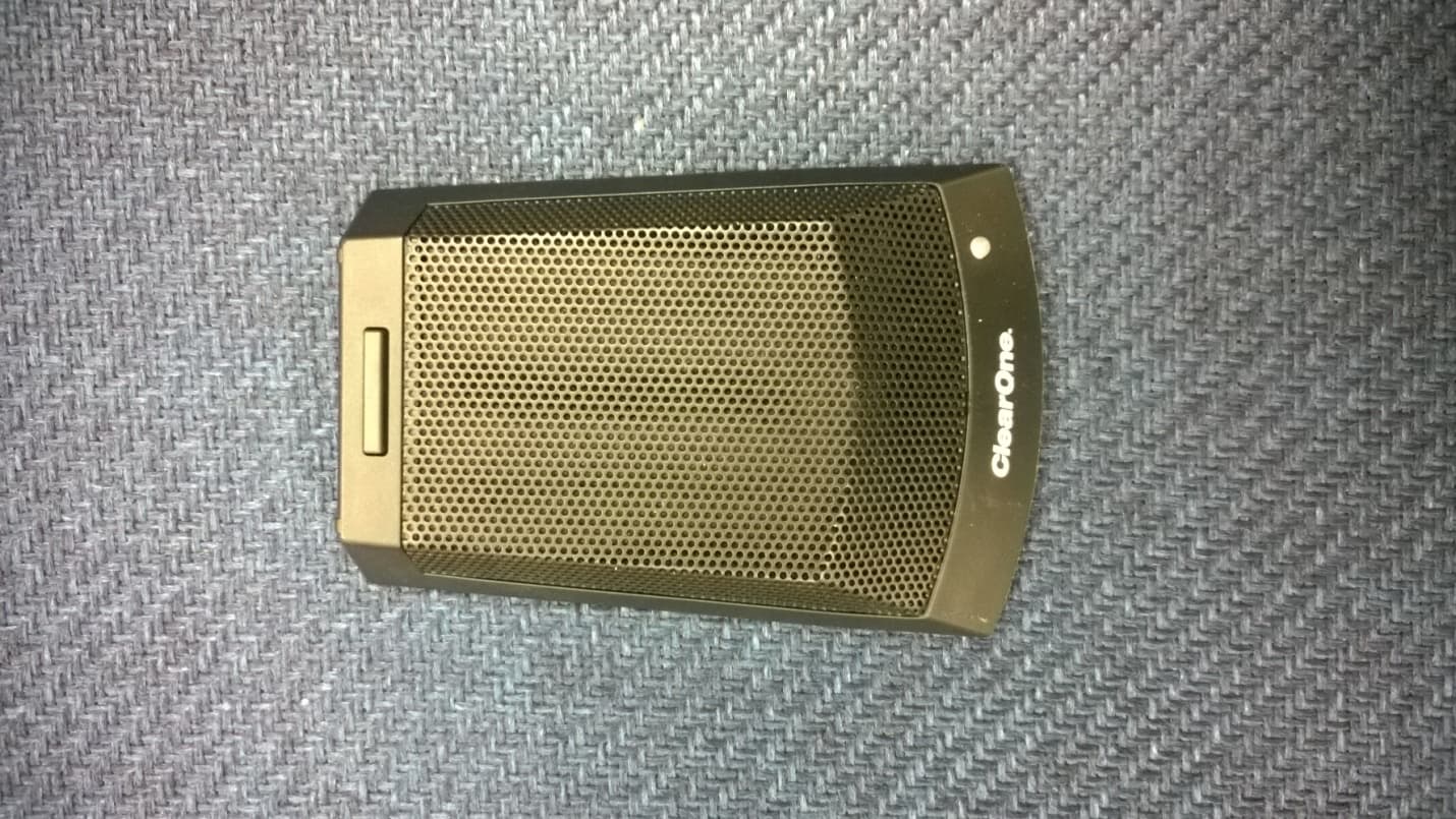
FBITABLETOP
Jan 01, 2015TABLE TOP WIRELESS MICROPHONE
Equipment Class
TBC - Licensed Broadcast Station Transmitter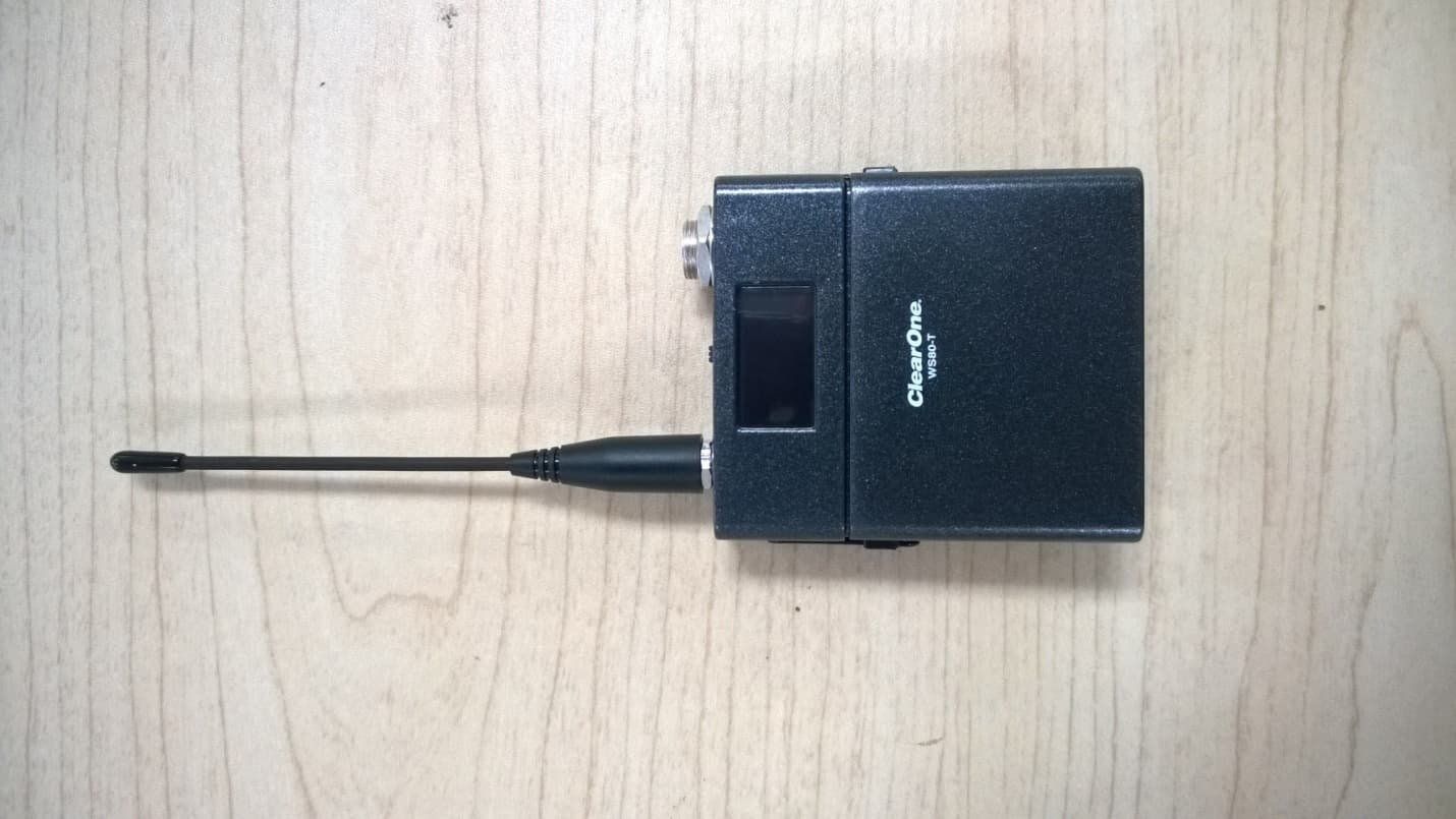
FBIBELTPACK
Dec 29, 2014BELTPACK WIRELESS MICROPHONE
Equipment Class
TBC - Licensed Broadcast Station Transmitter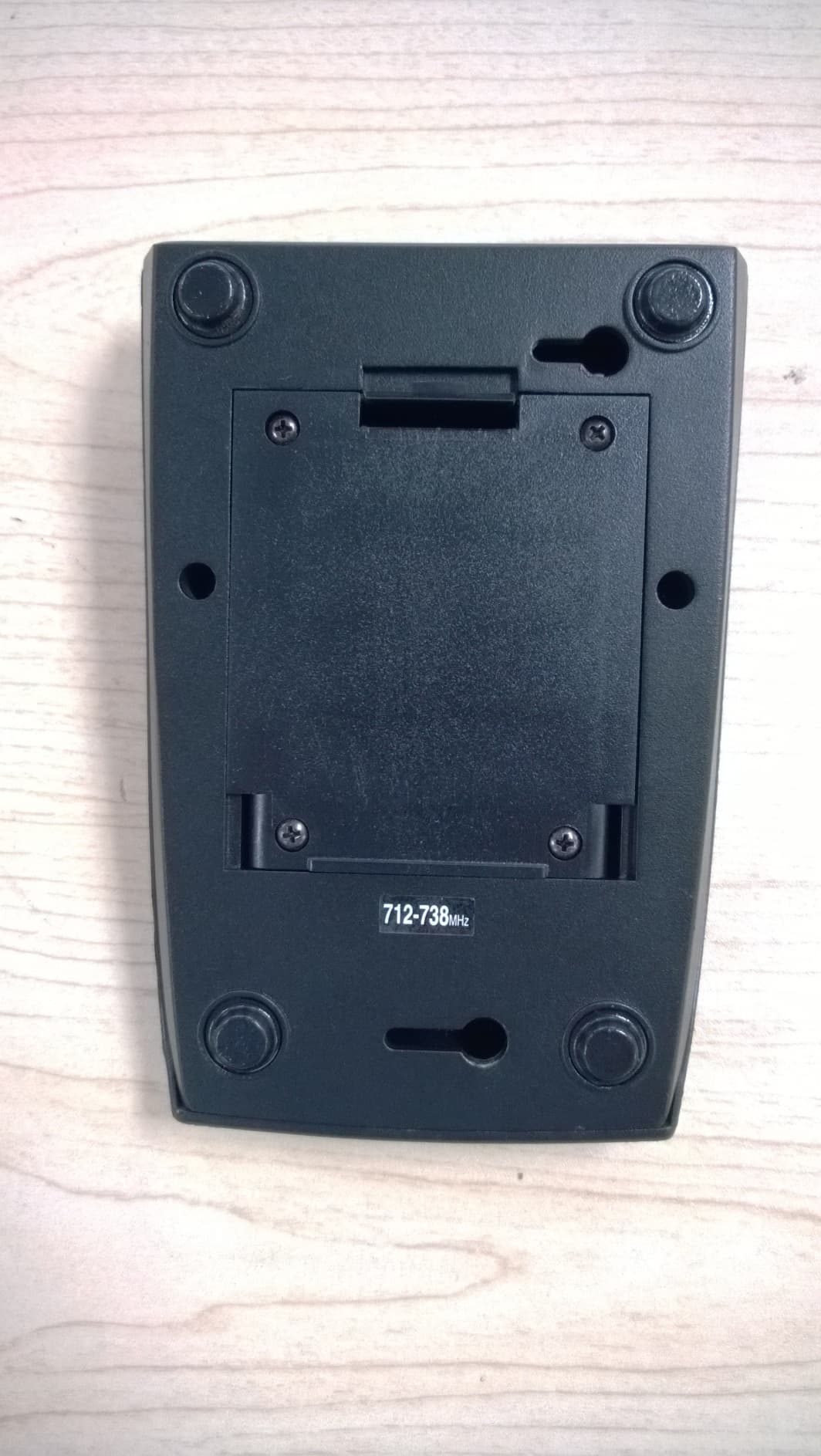
FBIGOOSENECK
Dec 29, 2014GOOSENECK WIRELESS MICROPHONE
Equipment Class
TBC - Licensed Broadcast Station Transmitter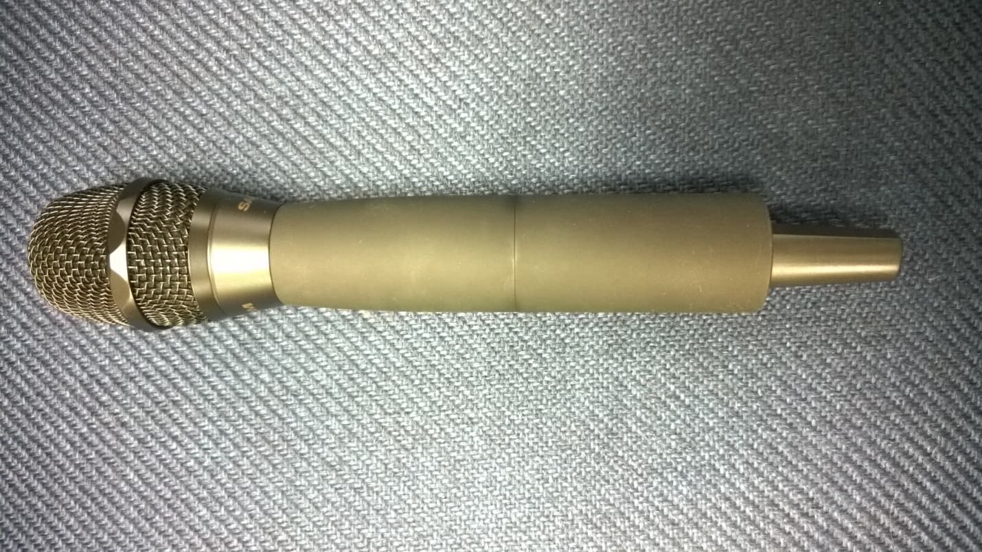
FBIHANDHELDMIC
Dec 29, 2014HANDHELD WIRELESS MICROPHONE
Equipment Class
TBF - Licensed Broadcast Transmitter Held to Face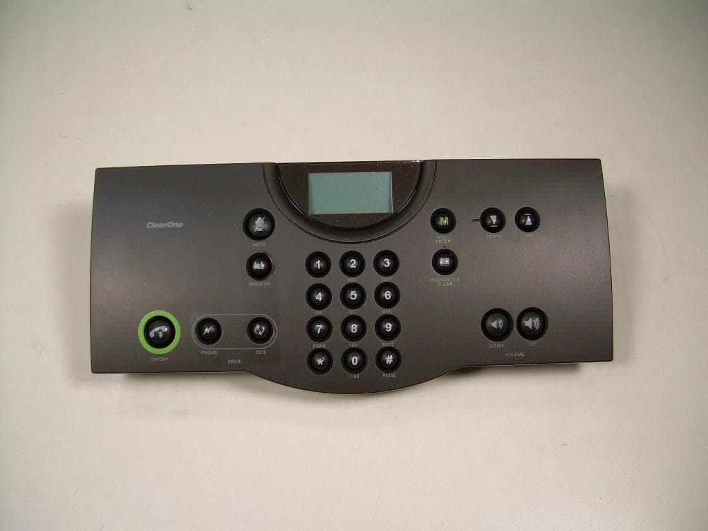
FBIDIALER
May 26, 2010Interact DIALER-W
Equipment Class
DTS - Digital Transmission System