FFMLW1100APWLAN Access Point
LG Electronics, Inc.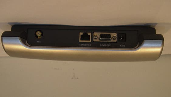
Click to zoom
Application Details
- Equipment Class
- DSS - Part 15 Spread Spectrum Transmitter
- Date of Grant
- Nov 28, 2001
- Application Purpose
- Original Equipment
- Date of Application
- Sep 17, 2001
- Equipment Note
- WLAN Access Point
- Frequency Range
- 2412.00000000 - 2462.00000000
- Company
- LG Electronics, Inc.
- Country
- South Korea
Documents & Files
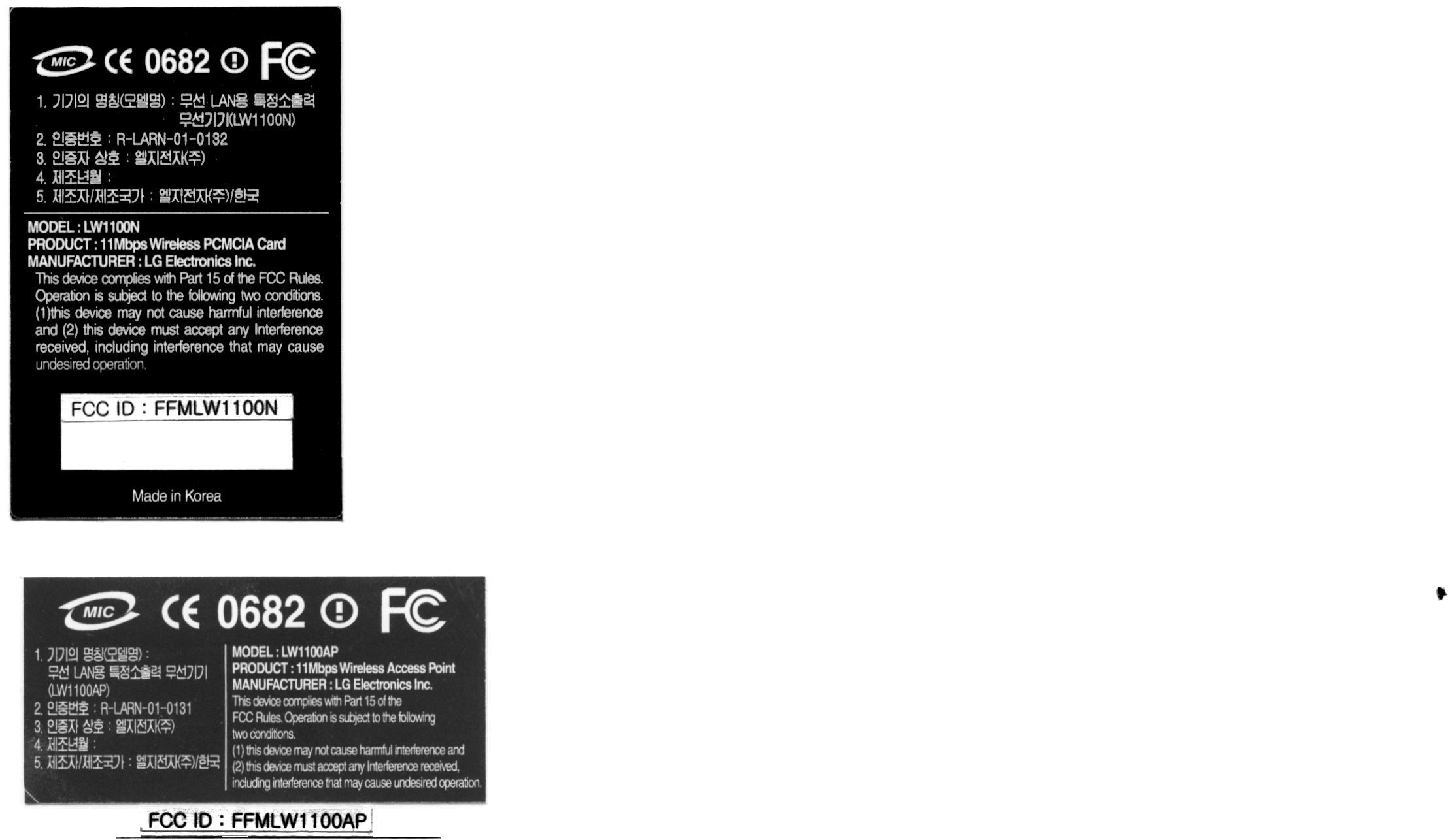
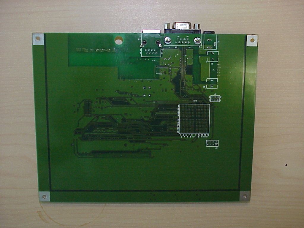
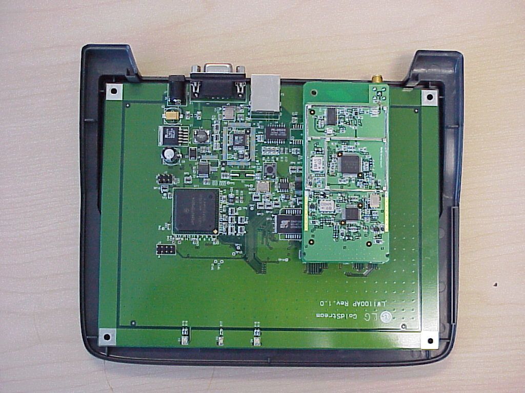
Document Text
Text extracted from the exhibit documents filed with the FCC. Open a document above to read the original.
Users Manual
Page 1 of 50 Wireless LAN Access Point User’s Guide LW1100AP Series Page 2 of 50 Contents Chapter 1 Introduction To The Wireless LAN 1.1 What’s the Wireless LAN? .......................................... 5 1.2 Wireless LAN Standard and Structure..............................6 Chapter 2 Setup GoldStream Access Point ...................... 13 2.1 Before You Begin Installation .................................... ....13 2.2 Installing The LG LW1100AP Series Access Point ...........................................15 Adjust the antennas ................................................15 Ethernet Cable Connection .......................................16 Connect The Power Pack .........................................17 Connect Serial Cable ...............................................18 Open Terminal Program ...........................................19 Configuration Change ..............................................21 2.3 Verifying the Operation of the LG Access Point .......... 28 Chapter 3 Access Point Management....................................30 3.1 Starting a Configuration Tool.............................................31 Access Point Connection. ..........................................32 Access Point Configuration Window..............................33 Terminal Window for Diagnosis ...................................37 Firmware Upgrade Window ........................................38 Firmware Upgrade Via Internet ...................................39 Firmware Upgrade Via Local Disk................................41 Access Point Detail Control........................................42 3.2 Setting Bridge Mode .....................................................43 Chapter 4 Troubleshooting ..................................................45 Page 3 of 50 Appendix Appendix A Cell Planning (Radio Range) ...................................46 Appendix B Technical Specification ..........................................48 Appendix C Channel Allocation ................................................50 Page 4 of 50 THE SPECIFICATIONS AND INFORMATION REGARDING THE PRODUCTS IN THIS MANUAL ARE SUBJECT TO CHANGE WITHOUT NOTICE. ALL STATEMENTS, INFORMATION, AND RECOMMENDATIONS IN THIS MANUAL ARE BELIEVED TO BE ACCURATE BUT ARE PRESENTED WITHOUT WARRANTY OF ANY KIND, EXPRESS OR IMPLIED. USERS MUST TAKE FULL RESPONSIBILITY FOR THEIR APPLICATION OF ANY PRODUCTS. THE SOFTWARE LICENSE AND LIMITED WARRANTY FOR THE ACCOMPANYING PRODUCT ARE SET FORTH IN THE INFORMATION PACKET THAT SHIPPED WITH THE PRODUCT AND ARE INCORPORATED HEREIN BY THIS REFERENCE. IF YOU ARE UNABLE TO LOCATE THE SOFTWARE LICENSE OR LIMITED WARRANTY, CONTACT YOUR LG REPRESENTATIVE FOR A COPY. The following information is for FCC compliance of Class A devices: This equipment has been tested and found to comply with the limits for a Class A digital device, pursuant to part 15 of the FCC rules. These limits are designed to provide reasonable protection against harmful interference when the equipment is operated in a commercial environment. This equipment generates, uses, and can radiate radio- frequency energy and, if not installed and used in accordance with the instruction manual, may cause harmful interference to radio communications. Operation of this equipment in a residential area is likely to cause harmful interference, in which case users will be required to correct the interference at their own expense. The following information is for FCC compliance of Class B devices: The equipment described in this manual generates and may radiate radio-frequency energy. If it is not installed in accordance with LG’s installation instructions, it may cause interference with radio and television reception. This equipment has been tested and found to comply with the limits for a Class B digital device in accordance with the specifications in part 15 of the FCC rules. These specifications are designed to provide reasonable protection against such interference in a residential installation. However, there is no guarantee that interference will not occur in a particular installation. Modifying the equipment without LG’s written authorization may result in the equipment no longer complying with FCC requirements for Class A or Class B digital devices. In that event, your right to use the equipment may be limited by FCC regulations, and you may be required to correct any interference to radio or television communications at your own expense. You can determine whether your equipment is causing interference by turning it off. If the interference stops, the LG equipment or one of its peripheral devices probably caused it. If the equipment causes interference to radio or television reception, try to correct the interference by using one or more of the following measures: • Turn the television or radio antenna until the interference stops. • Move the equipment to one side or the other of the television or radio. • Move the equipment farther away from the television or radio. • Plug the equipment into an outlet that is on a different circuit from the television or radio. (That is, make certain the equipment and the television or radios are on circuits controlled by different circuit breakers or fuses.) Page 5 of 50 Modifications to this product not authorized by LG Electronics Inc. could void the FCC approval and negate your authority to operate the product. FCC RF Radiation Exposure Statement This equipment complies with FCC RF radiation exposure limits set forth for an uncontrolled environment. This equipment should be installed and operated with a minimum distance of 20 centimeters between the radiator and your body. Important Note : LW1100AP Antenna type is unique reverse turn SMA connector, Use only the supplied antenna. Unauthorized antennas, modifications, or attachments could damage the transmitter and may violate FCC regulations. NOTWITHSTANDING ANY OTHER WARRANTY HEREIN, ALL DOCUMENT FILES AND SOFTWARE OF THESE SUPPLIERS ARE PROVIDED …
Text truncated - open the document above for the full version.
Cover Letter(s)
1 of 1 Date:7/19/2001 Federal Communications Commission Authorization and Evaluation Division Laboratory Division 7435 Oakland Mills Road Columbia, MD 21046 Re: LG Electronics Inc. , LG LW1100AP Request for withholding from public disclosure proprietary information submitted pursuant to an application for certification of a Wireless LAN FCC ID: FFMLW1100AP Sir/Madam: LG Electronics Inc. requests that certain materials submitted with this application for certification of the LG LW1100AP be withheld from public disclosure. This request is made under the provision of Section 0.457 (d) of the Commission’s Rule and Section 552 (b) (4) of the Freedom of Information Act, Trade Secrets. The items marked “Confidential” contain detailed Schematic diagram, Part lists, PCB layout, and Block diagram, submitted to the FCC for review with this application. The information contains proprietary information (trade secrets) regarding the circuit operation and capabilities (specific values of components, circuit design details and system architecture) which are the result of our extensive investment in research and development. Without the disclosed information, competitive organizations would take considerable more time to assess and develop a workable competitive product. Therefore, we believe that disclosure of these company guarded materials would compromise our leading position in this market. We therefore formally request that the materials marked “Confidential” be kept strictly confidential and not made available for inspection by any other party, except on a need to know basis for the sole purpose of the certification process. Sincerely yours, Network Export Team Assistant Manager William Oh
Cover Letter(s)
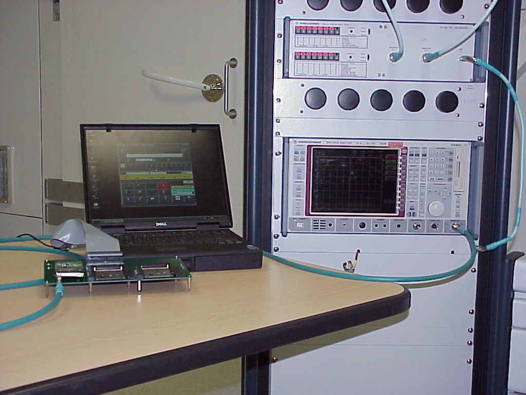
Page 1 of 1 Statement RF exposure The statements regarding the RF safety information (see file RF_exposure_Ant.doc) will be included in the final version of the manual. Explanation for using a test setup without the enclosure. In order to set the radio in the relevant test modes it was necessary to have access to the radio via a computer. Since it was a pure plastic enclosure, which has no influence to the electrical and electromagnetic performance, it was kept open during the test. Precautions were done to ensure that the worst-case conditions were measured. Lothar Schmidt Technical Manager EMC / Radio
External Photos
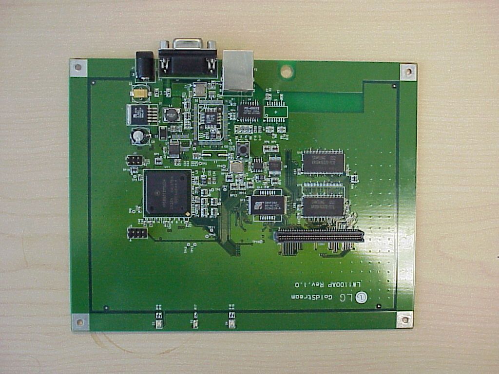
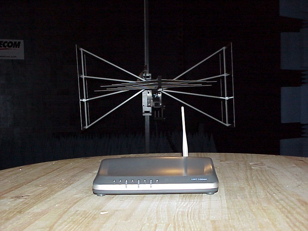
8.3 Front 8.4 Rear 8.4.2 Rear(without Antenna) 8.5 Side
Operational Description
WirelessLAN Access Point Model Name : LG LW1100AP July, 2001 LG Electronics Inc. Table of Contents 1. Introduction ....................................................................................3 2. Circuit Description ........................................................................... 3 3. Specifications ....................................................................................11 3.1 General Specification ......................................................... 11 3.2 Electrical Specification .........................................................11 3.3 Environmental Specification ...................................................11 3.4 Mechanical Specification ......................................................11 3. Layout ................................................................................................ 12 3.1 Block Layout ........................................................................ 12 3.2 PCB Profile ........................................................................... 15 4. Block Diagram ................................................................................. 16 5. Circuit Diagram ................................................................................. 18 6. Component Layout .................................................................................... 19 6.1 Top Side (Component Layer) .................................................................. 19 6.2 Bottom Side (Solder Layer) .................................................................. 20 6.3 RF Top Side - - - - - - - - - - - - - - - - - - - - - - - - - - - - - - 21 6.4 RF Botto side - - - - - - - - - - - - - - - - - - - - - - - - - - - - - 22 7. Part List ............................................................................................. 23 8. Photographs ............................................................................................. 24 9. Instruction Manual ................................................................................. 28 1. Introduction This paper describes the LG AP circuits, specifications,layouts and partlist etc. 2. Circuit Description 2.1 The Architecture The radio design is centered on the expected signal characteristics of the modulation method. A Differential Quadrature Phase Shift Keying (DQPSK) modulation encodes the data in terms of phase with minimal amplitude variation, improving noise immunity. This is joined with the IEEE 802.11 protocol standard Carrier Sense Multiple Access/Collision Avoidance (CSMA/CA) and with the FCC requirement for 10dB processing gain, to allow signals to be received with approximately 0dB Signal to Noise Ratio (SNR) for a 10 -5 Bit Error Rate (BER). The CSMA/CA protocol allows only one user, per channel, at a time (i.e., first come, first serve) making for a quieter medium. The processing gain, achieved by spreading the signal with a PN code, allows a faint signal to be pulled from the noise while suppressing non-correlating interferers. From the antenna, the received input is applied to the pre-select filter FL1. This filter is a two pole dielectric design, rejecting interferers outside the 2.4GHz ISM band and providing image rejection. The signal enters the HFA3683 RF/IF Converter, first passing through the integrated LNA section and then enters the down converter section of the HFA3683. Low-side local oscillator injection is used to mix down to the single intermediate frequency, 374MHz. The IF receive filter FL3, is a Surface Acoustic Wave (SAW) device used for channel selection within the band. The SAW output is reactively matched to the IF input of the HFA3783 Quadrature IF Modulator/Demodulator. In receive mode, the HFA3783 provides two limiting amplifiers, a quadrature baseband demodulator, and two baseband low pass filters. The two limiting amplifiers or limiters provide most of the receiver gain, giving the radio it’s sensitivity. The baseband circuit samples the waveform with 7-bit ADCs and then despreads and demodulates the received data. On the Transmit side, data can either be DBPSK or DQPSK modulated at 1MSPS (Mega Symbols Per Second), resulting in a baseband quadrature signal with I and Q components. These digital signals are output to the HFA3783 fifth order Butterworth low pass filters, which are used to provide shaping of the phase shift keyed (PSK) signal. The required transmit spectral mask, at the antenna, is -30dBc at the first side-lobe relative to the main lobe. The signals are then quadrature modulated up to IF using the same 2xLO used for the quadrature demodulation. The signal then goes to the high impedance input of the HFA3683 upconverting mixer for conversion to the 2.4GHz - 2.5GHz band. The mixer output goes to the pre-amplifier, in the HFA3683, amplifies the signal and easing the requirement for HFA3983 RFPA gain. FL2, a two pole dielectric bandpass filter, is used to suppress both transmit LO leakage and the undesired sideband. The HFA3983 RFPA amplifies the transmit signal to approximately +18dBm. The transmit sidelobe performance is approximately -30dBc. Allowing for a 3dB loss in the band select filter FL1, this gives a final output power of +15dBm. 2.2 Transmit Chain Front End Cascade Analysis The large gain in the Power Amplifier, HFA3983, keeps the signal level small for the whole chain before it. This helps conserve supply current and the cost associated with devices that need to handle large signals. The output power at the RF filter is shown as 15dBm, with the output of the Power Amplifier at 18dBm. The design has been optimized for the best use of supply current and cost of the PA. If the output power was lower, the supply current and cost of the PA could be saved with smaller and cheaper devices. If the output power was higher, the signal will be too close to the P1dB and the signal will have excessive distortion, causing regrowth of the side lobes. The transmitted signal must suppress side lobes to -30dB …
Text truncated - open the document above for the full version.
RF Exposure Info
CETECOM Inc. 411 Dixon Landing Road Milpitas, CA 95035 Federal Communication Commission Authorization and Evaluation Division 7435 Oakland Mills Road Columbia, MD 21046 Attention: Reviewing Engineer The LG Electronics Inc. is a regular 802.11b Wireless LAN Access Point using spread spectrum technique for wireless access of a PC to a LAN. Due to the construction and the intended use of the of a LAN access Point, the installation should be done as recommended in the manual in a area free from disturbances and this requires a distance under normal operating conditions of more than 20 cm. This information includes the following : A minimum separation distance of 20 cm must be maintained between the antenna and the person for this device to satisfy the RF exposure requirements of the FCC. The maximum output power for is 100 mW (20 dBm). Maximum EIRP of the equipment = 20 dBm (0.0100 W); equivalent to 8.66 V/m in 10 cm distance Regarding MPE limits, GPUC environment limits maximum exposure to 1 mW/cm 2. The power density is: at 20 centimeters from an antenna S = E 2 /3770=-13 H 2 = 0.01989 mW/cm 2 < 1 mW/ at 10 centimeters from an antenna S = E 2 /3770=-13 H 2 = 0.0795 mW/cm 2 < 1 mW/ Where: S = Power density (mW/cm 2) E = electrical field strength (V/m) Calculations are based on standard formula for calculating field strength at a distance and converting power density using free space impedance. Compliance is shown for the built in module, which have an external the antenna with a unique re ve rse d polarity SMA connector the module even for the distance of 10 cm. This is the distance given by the position of the antenna in the rear of the computer. If you should have any questions regarding this submission, please feel free to contact the undersigned. Yours tr ul y, Lothar Schmidt Technical Manager EMC/Radio CETECOM Inc.
RF Exposure Info
LG GoldStream FCC RF Radiation Exposure Statement This equipment complies with FCC RF radiation exposure limits set forth for an uncontrolled environment. This equipment should be installed and operated with a minimum distance of 20 centimeters between the radiator and your body. Important Note : LW1100AP Antenna type is unique reverse turn SMA connector, Use only the supplied antenna. Unauthorized antennas, modifications, or attachments could damage the transmitter and may violate FCC regulations.
Test Report
CETECOM Inc. CETECOM Inc. 411 Dixon Landing Road, Milpitas, CA-95035, USA Phone: +1 408 586 6200 Fax: +1 408 586 6299 www.cetecom.com Issued test report consists of 58 Pages Test report no.: 177 FCC/2001 FCC Part 15.247 LAN AP - LW1100AP (FCC ID:FFMLW1100AP) FCC LISTED, REG. NO.: 101450 & RECOGNIZED BY INDUSTRY CANADA IC – 3925 CETECOM Inc. Test report no.: 177 FCC/2001 Issued date:2001-08-14 Page 2 (68) Table of Contents 1 General information 1.1 Notes 1.2 Testing laboratory 1.3 Details of applicant 1.4 Application details 1.5 Test item 1.6 Test standards 2 Technical test 2.1 Summary of test results 2.2 Test report 1 General information 1.1 Notes The test results of this test report relate exclusively to the test item specified in 1.5. The CETECOM Inc. USA does not assume responsibility for any conclusions and generalisations drawn from the test results with regard to other specimens or samples of the type of the equipment represented by the test item. The test report may only be reproduced or published in full. Reproduction or publication of extracts from the report requires the prior written approval of the CETECOM Inc. USA. CETECOM Inc. Test report no.: 177 FCC/2001 Issued date:2001-08-14 Page 3 (68) 1.2 Testing laboratory CETECOM Inc. 411 Dixon Landing Road, Milpitas, CA-95035, USA Phone: +1 408 586 6200 Fax: +1 408 586 6299 E-mail: [email protected] Internet: www.cetecom.com 1.3 Details of applicant Name : LG Electronics Inc. Street : 60-39 Kasan-dong, Kumchon-gu City : Seoul 153-023 Country : Korea Telephone : +82 2 3289 3117 Telefax : +82 2 3289 3200 Contact : Mr. William KS. Oh e-mail : [email protected] 1.4 Application details Date of receipt of application : 2001-08-01 Date of receipt of test item : 2001-08-03 Date of test : 2001-08-08/09 1.5 Test item Manufacturer : LG Electronics Inc. Address : See above Name of EUT : Access Point Descriptin : Model No. : FCC ID : Additional informations: LAN Access Point LW1100AP Frequency : 2412 – 2462 MHz Type of modulation : DBPSK, DQPSK, CCK Number of channels : 11 Channels in US Antenna : Internal Power supply : +5VDC Temperature range : -10°C - +55°C CETECOM Inc. Test report no.: 177 FCC/2001 Issued date:2001-08-14 Page 4 (68) 1.6 Test standards FCC Part 15 §15.247 The tests were done following the public notice DA 00-705 released March 30, 2000 CETECOM Inc. Test report no.: 177 FCC/2001 Issued date:2001-08-14 Page 5 (68) 2 Technical test 2.1 Summary of test results No deviations from the technical specification(s) were ascertained in the course of the tests performed. TEST REPORT PREPARED BY: Harpreet Sidhu EMC & Radio Engineer: Technical responsibility for area of testing : 2001-08-14 EMC& Radio Lothar Schmidt Date Section Name Signature CETECOM Inc. Test report no.: 177 FCC/2001 Issued date:2001-08-14 Page 6 (68) 2.2 Testreport TEST REPORT Testreport no. : 177 FCC/2001 LAN AP - LW1100AP FCC ID: CETECOM Inc. Test report no.: 177 FCC/2001 Issued date:2001-08-14 Page 7 (68) TEST REPORT REFERENCE LIST OF MEASUREMENTS Paragraph PARAMETER TO BE MEASURED PAGE Transmitter parameters § 15.247 (a)(2) Spectrum Bandwith of a DSSS System 7 § 15.247 (b)(1) Maximum peak output power 11 § 15.247 (c)(1) Emission limitations 19 § 15.247 (d) Power Spectral Density 33 § 15.247 (e) Processing Gain of DSSS System 37 § 15.107 Conducted emissions 40 Receiver parameters § 15.209 Receiver Spurious Radiation 42 Test equipment listing 50 Test Site 51 Photographs of the equipment 53 CETECOM Inc. Test report no.: 177 FCC/2001 Issued date:2001-08-14 Page 8 (68) SPECTRUM BANDWITH OF DSSS-SYSTEM SUBCLAUSE § 15.247 (a)(2) TEST CONDITIONS 6 dB BANDWIDTH ( kHz ) Frequency (MHz) 2412 2437 2462 T nom ( 23 )°C V nom (5.0)V 11122 11122 11122 Measurement uncertainty ±3dB LIMIT SUBCLAUSE §15.247(a) (2) The minimum 6dB bandwith shall shall be at least 500 KHz CETECOM Inc. Test report no.: 177 FCC/2001 Issued date:2001-08-14 Page 9 (68) SPECTRUM BANDWITH OF DSSS-SYSTEM SUBCLAUSE § 15.247 (a)(2) Lowest Channel: 2412 MHz LIMIT SUBCLAUSE §15.247(a) (2) The minimum 6dB bandwith shall shall be at least 500 KHz , here 11.122 MHz CETECOM Inc. Test report no.: 177 FCC/2001 Issued date:2001-08-14 Page 10 (68) SPECTRUM BANDWITH OF DSSS-SYSTEM SUBCLAUSE § 15.247 (a)(2) Mid Channel: 2437 MHz LIMIT SUBCLAUSE §15.247(a) (2) The minimum 6dB bandwith shall shall be at least 500 KHz , here 11.122 MHz CETECOM Inc. Test report no.: 177 FCC/2001 Issued date:2001-08-14 Page 11 (68) CETECOM Inc. Test report no.: 177 FCC/2001 Issued date:2001-08-14 Page 12 (68) SPECTRUM BANDWITH OF DSSS-SYSTEM SUBCLAUSE § 15.247 (a)(2) Highest Channel: 2462 MHz LIMIT SUBCLAUSE §15.247(a) (2) The minimum 6dB bandwith shall shall be at least 500 KHz , here 11.122 MHz CETECOM Inc. Test report no.: 177 FCC/2001 Issued date:2001-08-14 Page 13 (68) CETECOM Inc. Test report no.: 177 FCC/2001 Issued date:2001-08-14 Page 14 (68) MAXIMUM PEAK OUTPUT POWER SUBCLAUSE § 15.247 (b) (1) (CONDUCTED) TEST CONDITIONS MAXIMUM PEAK OUTPUT POWER (dBm) Frequency (MHz) 2412 2437 2462 Pk 11.69 Pk 11.67 Pk 11.25 T nom ( 23 )°C V nom (5.0)V Av 6.56 Av 6.68 Av 6.28 Measurement uncertainty ±3dB LIMIT SUBCLAUSE § 15.247 (b) (1) Frequency range RF power output 2400-2483.5 MHz / 5725 – 5850 MHz 1.0 Watt CETECOM Inc. Test report no.: 177 FCC/2001 Issued date:2001-08-14 Page 15 (68) MAXIMUM PEAK OUTPUT POWER (CONDUCTED) Lowest Channel: 2412 MHz The RBW was set to the maximum available bandwith of the Analyzer (10MHz). This is valid for the conducted output power as well as for the EIRP measurements. CETECOM Inc. Test report no.: 177 FCC/2001 Issued date:2001-08-14 Page 16 (68) MAXIMUM PEAK OUTPUT POWER (CONDUCTED) Mid Channel: 2437 MHz CETECOM Inc. Test report no.: 177 FCC/2001 Issued date:2001-08-14 Page 17 (68) MAXIMUM PEAK OUTPUT POWER (CONDUCTED) Highest Channel: 2462 MHz CETECOM Inc. Test report no.: 177 FCC/2001 Issued date:2001-08-14 Page 18 (68) MAXIMUM PEAK OUTPUT POWER (EIRP) SUBCLAUSE § 15.247 (b) (1) (RADIATED) TEST CONDITIONS …
Text truncated - open the document above for the full version.
Test Report
CETECOM Inc. CETECOM Inc. 411 Dixon Landing Road, Milpitas, CA-95035, USA Phone: +1 408 586 6200 Fax: +1 408 586 6299 www.cetecom.com Issued test report consists of 58 Pages Test report no.: 177 FCC/2001 FCC Part 15.247 LAN AP - LW1100AP (FCC ID:FFMLW1100AP) FCC LISTED, REG. NO.: 101450 & RECOGNIZED BY INDUSTRY CANADA IC – 3925 CETECOM Inc. Test report no.: 177 FCC/2001 Issued date:2001-08-14 Page 2 (58) Table of Contents 1 General information 1.1 Notes 1.2 Testing laboratory 1.3 Details of applicant 1.4 Application details 1.5 Test item 1.6 Test standards 2 Technical test 2.1 Summary of test results 2.2 Test report 1 General information 1.1 Notes The test results of this test report relate exclusively to the test item specified in 1.5. The CETECOM Inc. USA does not assume responsibility for any conclusions and generalisations drawn from the test results with regard to other specimens or samples of the type of the equipment represented by the test item. The test report may only be reproduced or published in full. Reproduction or publication of extracts from the report requires the prior written approval of the CETECOM Inc. USA. 1.2 Testing laboratory CETECOM Inc. 411 Dixon Landing Road, Milpitas, CA-95035, USA Phone: +1 408 586 6200 Fax: +1 408 586 6299 E-mail: [email protected] Internet: www.cetecom.com CETECOM Inc. Test report no.: 177 FCC/2001 Issued date:2001-08-14 Page 3 (58) 1.3 Details of applicant Name : LG Electronics Inc. Street : 60-39 Kasan-dong, Kumchon-gu City : Seoul 153-023 Country : Korea Telephone : +82 2 3289 3117 Telefax : +82 2 3289 3200 Contact : Mr. William KS. Oh e-mail : [email protected] 1.4 Application details Date of receipt of application : 2001-08-01 Date of receipt of test item : 2001-08-03 Date of test : 2001-08-08/09 1.5 Test item Manufacturer : LG Electronics Inc. Address : See above Name of EUT : Access Point Descriptin : Model No. : FCC ID : Additional informations: LAN Access Point LW1100AP Frequency : 2412 – 2462 MHz Type of modulation : DBPSK, DQPSK, CCK Number of channels : 11 Channels in US Antenna : Internal Power supply : +5VDC Temperature range : -10°C - +55°C 1.6 Test standards FCC Part 15 §15.247 The tests were done following the public notice DA 00-705 released March 30, 2000 CETECOM Inc. Test report no.: 177 FCC/2001 Issued date:2001-08-14 Page 4 (58) 2 Technical test 2.1 Summary of test results No deviations from the technical specification(s) were ascertained in the course of the tests performed. TEST REPORT PREPARED BY: Harpreet Sidhu EMC & Radio Engineer: Technical responsibility for area of testing : 2001-10-17 EMC & Radio Lothar Schmidt Date Section Name Signature CETECOM Inc. Test report no.: 177 FCC/2001 Issued date:2001-08-14 Page 5 (58) 2.2 Testreport TEST REPORT Testreport no. : 177 FCC/2001 LAN AP - LW1100AP CETECOM Inc. Test report no.: 177 FCC/2001 Issued date:2001-08-14 Page 6 (58) TEST REPORT REFERENCE LIST OF MEASUREMENTS Paragraph PARAMETER TO BE MEASURED PAGE Transmitter parameters § 15.247 (a)(2) Spectrum Bandwith of a DSSS System 7 § 15.247 (b)(1) Maximum peak output power 11 § 15.247 (c)(1) Emission limitations 19 § 15.247 (d) Power Spectral Density 33 § 15.247 (e) Processing Gain of DSSS System 37 § 15.107 Conducted emissions 40 Receiver parameters § 15.209 Receiver Spurious Radiation 42 Test equipment listing 50 Test Site 51 Photographs of the equipment 53 CETECOM Inc. Test report no.: 177 FCC/2001 Issued date:2001-08-14 Page 7 (58) SPECTRUM BANDWITH OF DSSS-SYSTEM SUBCLAUSE § 15.247 (a)(2) TEST CONDITIONS 6 dB BANDWIDTH ( kHz ) Frequency (MHz) 2412 2437 2462 T nom ( 23 )°C V nom (5.0)V 11122 11122 11122 Measurement uncertainty ±3dB LIMIT SUBCLAUSE §15.247(a) (2) The minimum 6dB bandwith shall shall be at least 500 KHz CETECOM Inc. Test report no.: 177 FCC/2001 Issued date:2001-08-14 Page 8 (58) SPECTRUM BANDWITH OF DSSS-SYSTEM SUBCLAUSE § 15.247 (a)(2) Lowest Channel: 2412 MHz LIMIT SUBCLAUSE §15.247(a) (2) The minimum 6dB bandwith shall shall be at least 500 KHz , here 11.122 MHz CETECOM Inc. Test report no.: 177 FCC/2001 Issued date:2001-08-14 Page 9 (58) SPECTRUM BANDWITH OF DSSS-SYSTEM SUBCLAUSE § 15.247 (a)(2) Mid Channel: 2437 MHz LIMIT SUBCLAUSE §15.247(a) (2) The minimum 6dB bandwith shall shall be at least 500 KHz , here 11.122 MHz CETECOM Inc. Test report no.: 177 FCC/2001 Issued date:2001-08-14 Page 10 (58) SPECTRUM BANDWITH OF DSSS-SYSTEM SUBCLAUSE § 15.247 (a)(2) Highest Channel: 2462 MHz LIMIT SUBCLAUSE §15.247(a) (2) The minimum 6dB bandwith shall shall be at least 500 KHz , here 11.122 MHz CETECOM Inc. Test report no.: 177 FCC/2001 Issued date:2001-08-14 Page 11 (58) MAXIMUM PEAK OUTPUT POWER SUBCLAUSE § 15.247 (b) (1) (CONDUCTED) TEST CONDITIONS MAXIMUM PEAK OUTPUT POWER (dBm) Frequency (MHz) 2412 2437 2462 Pk 11.69 Pk 11.67 Pk 11.25 T nom ( 23 )°C V nom (5.0)V Av 6.56 Av 6.68 Av 6.28 Measurement uncertainty ±3dB 0.5 dB have to added to the values measured and reported in the table. (due to bandwidth correction by calculated as (10 log 6dB BW/used BW ) 10 log 11.12/10 = 0.5 dB) LIMIT SUBCLAUSE § 15.247 (b) (1) Frequency range RF power output 2400-2483.5 MHz / 5725 – 5850 MHz 1.0 Watt CETECOM Inc. Test report no.: 177 FCC/2001 Issued date:2001-08-14 Page 12 (58) MAXIMUM PEAK OUTPUT POWER (CONDUCTED) Lowest Channel: 2412 MHz The RBW was set to the maximum available bandwith of the Analyzer (10MHz). This is valid for the conducted output power as well as for the EIRP measurements. CETECOM Inc. Test report no.: 177 FCC/2001 Issued date:2001-08-14 Page 13 (58) MAXIMUM PEAK OUTPUT POWER (CONDUCTED) Mid Channel: 2437 MHz CETECOM Inc. Test report no.: 177 FCC/2001 Issued date:2001-08-14 Page 14 (58) MAXIMUM PEAK OUTPUT POWER (CONDUCTED) Highest Channel: 2462 MHz CETECOM Inc. Test report no.: 177 FCC/2001 Issued date:2001-08-14 Page 15 (58) MAXIMUM PEAK OUTPUT POWER (EIRP) SUBCLAUSE § 15.247 (b) (1) (RADIATED) TEST CONDITIONS MAXIMUM PEAK OUTPUT POWER (dBm) Frequency (MHz) 2412 2437 2462 Pk 15.61 Pk 1…
Text truncated - open the document above for the full version.
Test Report
Processing Gain of a Direct Sequence Spread Spectrum, FCC CFR 47, Para.15.247(e) Product Name : LW1100AP FCC Requirements: The Processing gain of a direct sequence system shall be at least 10 dB. The Processing gain shall be determined from the ratio in dB of the signal-to-noise ratio with the system spreading code turned off to the signal to noise ratio with the system spreading code turned on, as measured at the demodulated out of the receiver. Environmental Condition: Room temperature and Humidity : +25 °C and 50% Power Input: DC Power from the computer Test Equipment : NOEquipmentsVendorModel NameDescription 1Spectrum AnalyzerAgilentHP8595E9KHz ~ 22 GHz 2Signal GeneratorAgilentE4421A 3Power MeterAgilentHP438A 4Attenuator10 dB, 20 dB 5Step AttenuatorWeinschelAE117A-69-1170 dB 6Step AttenuatorWeinschelAF119A-99-3399 Db 7Power SplitterAceTeq. 8ComputerSamboDreamsys Method of measurement: Jamming Margin Method The processing gain may be measured using the CW jamming method. Figure1 shows the test configuration. The test consists of stepping a signal generator in 50 KHz increments across the passband of the system. At each point, the generator level required to produce the recommended Bit Error Rate(BER) is recorded. This level is the jammer level. The outp…
Text truncated - open the document above for the full version.
Contact Information
Applicant
GeunChang Do
Technical Contact
CETECOM Inc.Lothar Schmidt
[email protected]408-586-6214
411 Dixon Landing · Milpitas, California · United States
Non-Technical Contact
CETECOM Inc.Lothar Schmidt
[email protected]408-586-6214
Test Firm
Cetecom Inc.Lothar Schmidt
Technical Specifications
| # | Rule Parts | Frequency Range | Power Output |
|---|---|---|---|
| 1 | 15C | 2.41 GHz - 2.46 GHz | 38.00 mW |
Other Applications from LG Electronics, Inc.
FFMHG10ZZ0ENCXLUS
Dec 12, 2012SMART GATEWAY
Equipment Class
DTS - Digital Transmission System
FFMXTICK-BAPL
Jul 14, 2004USB Drive
Equipment Class
JBP - Part 15 Class B Computing Device Peripheral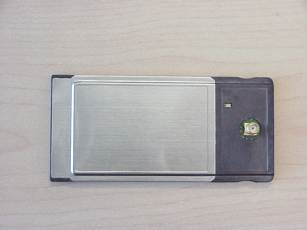
FFMLW1100N
Oct 25, 2001LP PCMCIA Card, model LW1100N
Equipment Class
DSS - Part 15 Spread Spectrum Transmitter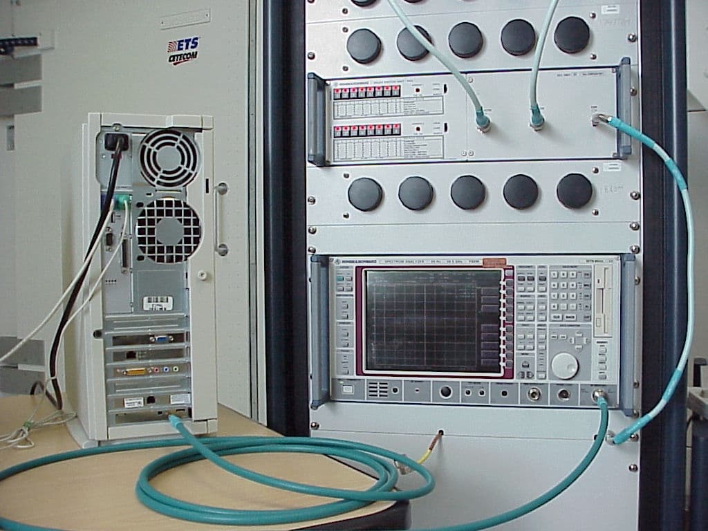
FFMLW1100P
Jul 10, 2001Wireless LAN PCI Card
Equipment Class
DSS - Part 15 Spread Spectrum Transmitter
FFMGT-8310C
Dec 07, 2000Cordless Phone
Equipment Class
DSS - Part 15 Spread Spectrum Transmitter