FFMLW1100PWireless LAN PCI Card
LG Electronics, Inc.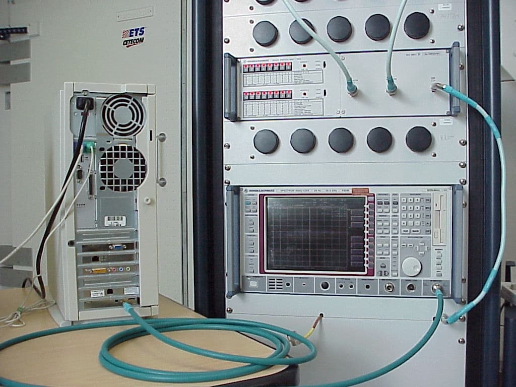
Click to zoom
Application Details
- Equipment Class
- DSS - Part 15 Spread Spectrum Transmitter
- Date of Grant
- Jul 10, 2001
- Application Purpose
- Original Equipment
- Date of Application
- Jul 10, 2001
- Equipment Note
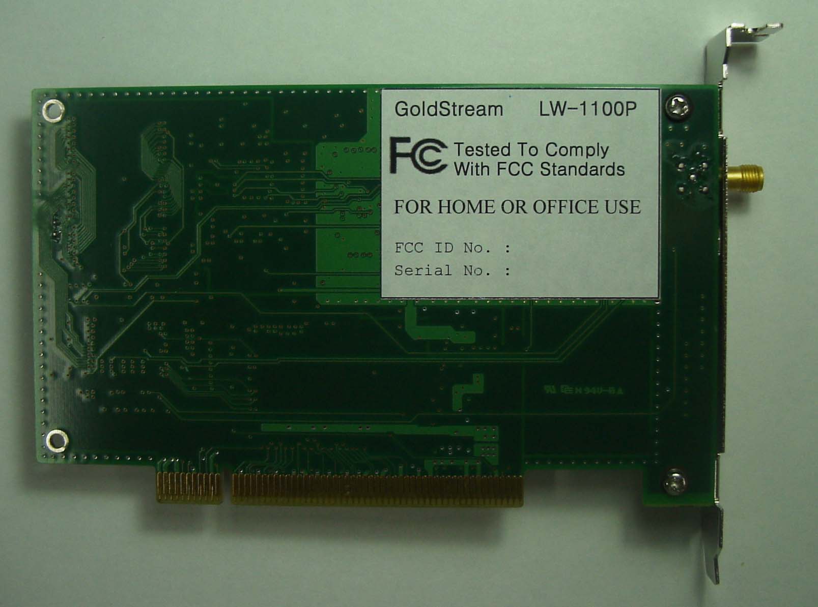
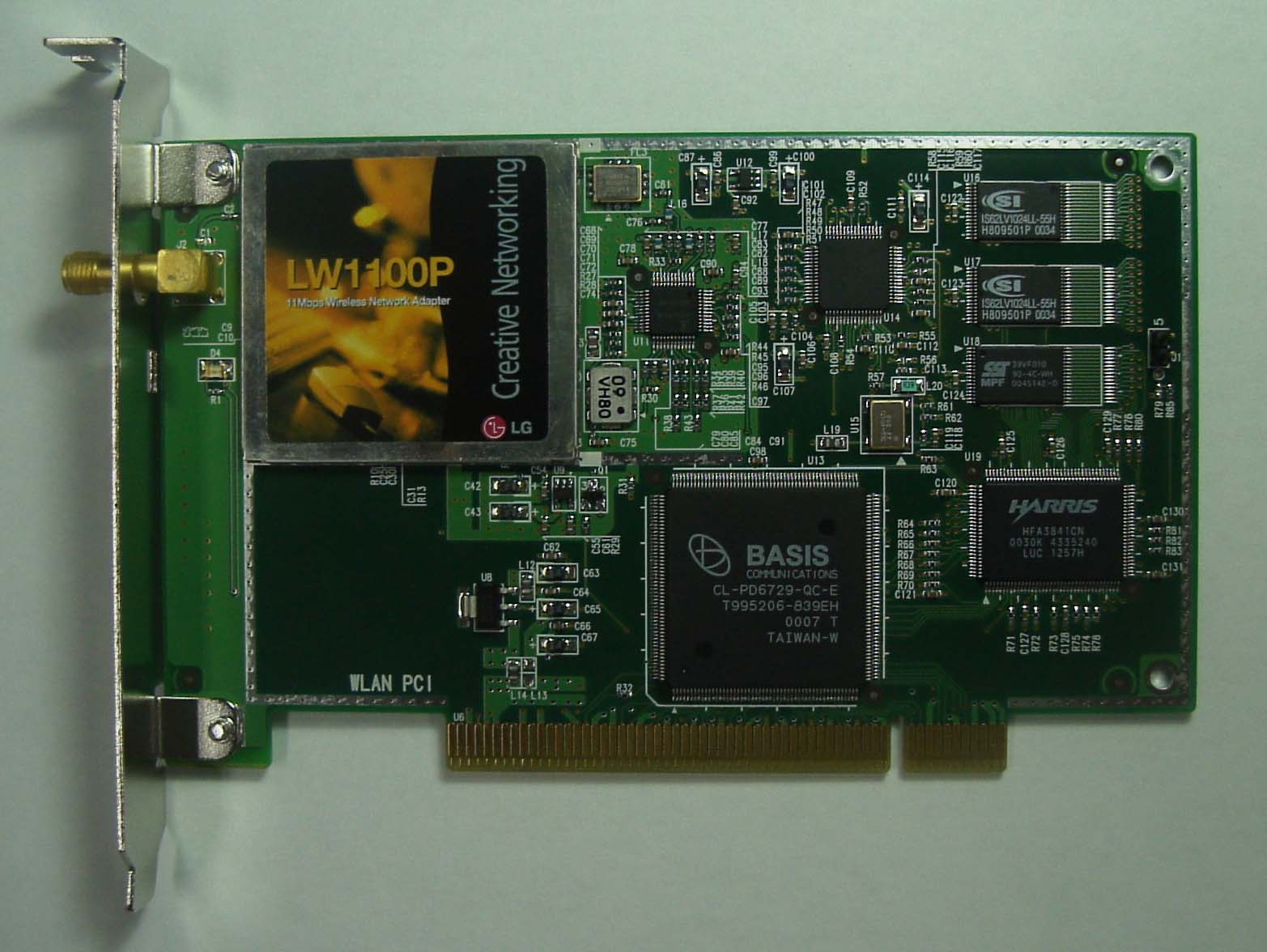
- Wireless LAN PCI Card
- Frequency Range
- 2400.00000000 - 2483.50000000
- Company
- LG Electronics, Inc.
- Country
- South Korea
Documents & Files
Document Text
Text extracted from the exhibit documents filed with the FCC. Open a document above to read the original.
Users Manual
LG GoldStream Page 1 of 39 LG GoldStream Wireless LAN PC Card User’s Guide LW1100N/LWL-1100P LG GoldStream Page 2 of 39 Contents Chapter 1 Introduction To The Wireless LAN 1.1 What’s the Wireless LAN? .......................................... 5 1.2 Wireless LAN Standard and Structure..............................6 Chapter 2 Before You Start GoldStream...............................12 Chapter 3 Installing GoldStream Card On The Windows OS 3.1 Installing PC Card Adapter. ...........................................13 3.1.1 Installing the PC Card Driver for Windows OS... ...14 3.1.2 PC Card (PCMCIA) Network Configuration .........18 3.1.3 Uninstalling PC Card Software .........................23 3.1.4 Remove PC Card from PC card socket ...............23 3.1.5 GoldStream Configuration Utility ...................... 24 3.2 PCI Card Installation .....................................................28 3.2.1 Installing PCI Card Adapter ...............................29 3.2.2 Installing PCI Card Driver ..................................31 3.2.3 PCI Card Network Configuration .........................31 3.3 Troubleshooting ...........................................................32 Appendix Appendix A Cell Planning (Radio Range) ...................................34 Appendix B Technical Specification ........................................36 Appendix C Channel Allocation ...............................................38 LG GoldStream Page 3 of 39 THE SPECIFICATIONS AND INFORMATION REGARDING THE PRODUCTS IN THIS MANUAL ARE SUBJECT TO CHANGE WITHOUT NOTICE. ALL STATEMENTS, INFORMATION, AND RECOMMENDATIONS IN THIS MANUAL ARE BELIEVED TO BE ACCURATE BUT ARE PRESENTED WITHOUT WARRANTY OF ANY KIND, EXPRESS OR IMPLIED. USERS MUST TAKE FULL RESPONSIBILITY FOR THEIR APPLICATION OF ANY PRODUCTS. THE SOFTWARE LICENSE AND LIMITED WARRANTY FOR THE ACCOMPANYING PRODUCT ARE SET FORTH IN THE INFORMATION PACKET THAT SHIPPED WITH THE PRODUCT AND ARE INCORPORATED HEREIN BY THIS REFERENCE. IF YOU ARE UNABLE TO LOCATE THE SOFTWARE LICENSE OR LIMITED WARRANTY, CONTACT YOUR LG REPRESENTATIVE FOR A COPY. The following information is for FCC compliance of Class B devices: The equipment described in this manual generates and may radiate radio-frequency energy. If it is not installed in accordance with LG’s installation instructions, it may cause interference with radio and television reception. This equipment has been tested and found to comply with the limits for a Class B digital device in accordance with the specifications in part 15 of the FCC rules. These specifications are designed to provide reasonable protection against such interference in a residential installation. However, there is no guarantee that interference will not occur in a particular installation. Modifying the equipment without LG’s written authorization may result in the equipment no longer complying with FCC requirements for Class A or Class B digital devices. In that event, your right to use the equipment may be limited by FCC regulations, and you may be required to correct any interference to radio or television communications at your own expense. You can determine whether your equipment is causing interference by turning it off. If the interference stops, the LG equipment or one of its peripheral devices probably caused it. If the equipment causes interference to radio or television reception, try to correct the interference by using one or more of the following measures: • Turn the television or radio antenna until the interference stops. • Move the equipment to one side or the other of the television or radio. • Move the equipment farther away from the television or radio. • Plug the equipment into an outlet that is on a different circuit from the television or radio. (That is, make certain the equipment and the television or radios are on circuits controlled by different circuit breakers or fuses.) Modifications to this product not authorized by LG Systems Co., Ltd. could void the FCC approval and negate your authority to operate the product. NOTWITHSTANDING ANY OTHER WARRANTY HEREIN, ALL DOCUMENT FILES AND SOFTWARE OF THESE SUPPLIERS ARE PROVIDED “AS IS” WITH ALL FAULTS. LG AND THE ABOVE-NAMED SUPPLIERS DISCLAIM ALL WARRANTIES, EXPRESSED OR IMPLIED, INCLUDING, WITHOUT LIMITATION, THOSE OF MERCHANTABILITY, FITNESS FOR A PARTICULAR PURPOSE AND LG GoldStream Page 4 of 39 NONINFRINGEMENT OR ARISING FROM A COURSE OF DEALING, USAGE, OR TRADE PRACTICE. IN NO EVENT SHALL LG OR ITS SUPPLIERS BE LIABLE FOR ANY INDIRECT, SPECIAL, CONSEQUENTIAL, OR INCIDENTAL DAMAGES, INCLUDING, WITHOUT LIMITATION, LOST PROFITS OR LOSS OR DAMAGE TO DATA ARISING OUT OF THE USE OR INABILITY TO USE THIS MANUAL, EVEN IF LG OR ITS SUPPLIERS HAVE BEEN ADVISED OF THE POSSIBILITY OF SUCH DAMAGES. GoldStream, the LG logo are registered trademarks of LG Systems Co., Ltd. or its affiliates in the Korea, U.S. and certain other countries. All other trademarks mentioned in this document are the property of their respective owners. The use of the word partner does not imply a partnership relationship between LG and any of its resellers. Using the LG GoldStream Card Copyright© 2000, LG Systems Co., Ltd All rights reserved. LG GoldStream Page 5 of 39 Chapter 1 Introduction To The Wireless LAN A wireless LAN (WLAN) is a flexible data communication system implemented as an extension to, or as an alternative for, a wired LAN within a building or campus. Using electromagnetic waves, WLANs transmit and receive data over the air, minimizing the need for wired connections. Thus, WLANs combine data connectivity with user mobility, and, through simplified configuration, enable movable LANs. WLANs have gained strong popularity in a number of vertical markets, including the health-care, retail, manufacturing, warehousing, and academic arenas. These industries have profited from the productivity gains of using hand-held terminals and notebook computers to transmit real-time information to centr…
Text truncated - open the document above for the full version.
Users Manual
LG GoldStream FCC NOTICE This equipment has been tested and found to comply with the limits for a Class B digital device, pursuant to part 15 of the FCC Rules. These limits are designed to provide reasonable protection against harmful interference in a residential installation. This equipment generates, uses and can radiate radio frequency energy and, if not installed and used in accordance with the instructions, may cause harmful interference to radio communication. However, there is no guarantee that interference will not occur in a particular installation. If this equipment does cause harmful interference to radio or television reception, which can be determined by turning the equipment off and on, the user is encouraged to try to correct the interference by one or more of the following measures : - Reorient or relocate the receiving antenna. - Increase the separation between the equipment and receiver. - Connect the equipment into an outlet on a circuit difference from that to which the receiver is connected. - Consult the dealer of an experienced radio/TV technician for help. NOTE : The manufacturer is not responsible for any radio or TV interference caused by unauthorized modifications to this equipment. Such modifications could void the user's authority to operate the equipment. THIS DEVICE COMPLIES WITH PART 15 OF THE FCC RULES. OPERATION IS SUBJECT TO THE FOLLOWING TWO CONDITIONS: (1) THIS DEVICE MAY NOT CAUSE HARMFUL INTERFERENCE, AND (2) THIS DEVICE MUST ACCEPT ANY INTERFERENCE RECEIVED, INCLUDING INTERFERENCE THAT MAY CAUSE UNDERSIRED OPERATION.
Block Diagram
LG GoldStream WilessLAN PCI Card Model Name : GoldStream Model No. : LW1100P May , 2001 LG Electronics Inc. LG GoldStream Table of Contents 1. Introduction ....................................................................................3 2. Circuit Description ........................................................................... 3 3. Specifications ....................................................................................9 3.1 General Specification ......................................................... 9 3.2 Electrical Specification ......................................................... 9 3.3 Environmental Specification ...................................................9 3.4 Mechanical Specification ......................................................10 3. Layout ................................................................................................ 10 3.1 Block Layout ........................................................................ 10 3.2 PCB Profile ........................................................................... 10 4. Block Diagram ................................................................................. 11 5. Circuit Diagram ................................................................................. 12 6. Component Layout .................................................................................... 13 6.1 Top Side (Component Layer) .................................................................. 13 6.2 Bottom Side (Solder Layer) .................................................................. 14 7. Part List ............................................................................................. 15 8. Photographs ............................................................................................. 16 9. Instruction Manual ................................................................................. 17 LG GoldStream 1. Introduction This paper describes the GoldStream PCI Card circuits, specifications,layouts and partlist etc. 2. Circuit Description 2.1 The Architecture The radio design is centered on the expected signal characteristics of the modulation method. A Differential Quadrature Phase Shift Keying (DQPSK) modulation encodes the data in terms of phase with minimal amplitude variation, improving noise immunity. This is joined with the IEEE 802.11 protocol standard Carrier Sense Multiple Access/Collision Avoidance (CSMA/CA) and with the FCC requirement for 10dB processing gain, to allow signals to be received with approximately 0dB Signal to Noise Ratio (SNR) for a 10 -5 Bit Error Rate (BER). The CSMA/CA protocol allows only one user, per channel, at a time (i.e., first come, first serve) making for a quieter medium. The processing gain, achieved by spreading the signal with a PN code, allows a faint signal to be pulled from the noise while suppressing non-correlating interferers. From the antenna, the received input is applied to the pre-select filter FL1. This filter is a two pole dielectric design, rejecting interferers outside the 2.4GHz ISM band and providing image rejection. The signal enters the HFA3683 RF/IF Converter, first passing through the integrated LNA section and then enters the down converter section of the HFA3683. Low-side local oscillator injection is used to mix down to the single intermediate frequency, 374MHz. The IF receive filter FL3, is a Surface Acoustic Wave (SAW) device used for channel selection within the band. The SAW output is reactively matched to the IF input of the HFA3783 Quadrature IF Modulator/Demodulator. In receive mode, the HFA3783 provides two limiting amplifiers, a quadrature baseband demodulator, and two baseband low pass filters. The two limiting amplifiers or limiters provide most of the receiver gain, giving the radio it’s sensitivity. The baseband circuit samples the waveform with 7-bit ADCs and then despreads and demodulates the received data. On the Transmit side, data can either be DBPSK or DQPSK modulated at 1MSPS (Mega Symbols Per Second), resulting in a baseband quadrature signal with I and Q components. These digital signals are output to the HFA3783 fifth order Butterworth low pass filters, which are used to provide shaping of the phase shift keyed (PSK) signal. The required transmit spectral mask, at the antenna, is -30dBc at the first side-lobe relative to the main lobe. The signals are then quadrature modulated up to IF using the same 2xLO used for the quadrature demodulation. The signal then goes to the high impedance input of the HFA3683 upconverting mixer for conversion to the 2.4GHz - 2.5GHz band. The mixer output goes to the pre-amplifier, in the HFA3683, amplifies the signal and easing the requirement for HFA3983 RFPA gain. LG GoldStream FL2, a two pole dielectric bandpass filter, is used to suppress both transmit LO leakage and the undesired sideband. The HFA3983 RFPA amplifies the transmit signal to approximately +18dBm. The transmit sidelobe performance is approximately -30dBc. Allowing for a 3dB loss in the band select filter FL1, this gives a final output power of +15dBm. 2.2 Transmit Chain Front End Cascade Analysis The large gain in the Power Amplifier, HFA3983, keeps the signal level small for the whole chain before it. This helps conserve supply current and the cost associated with devices that need to handle large signals. The output power at the RF filter is shown as 15dBm, with the output of the Power Amplifier at 18dBm. The design has been optimized for the best use of supply current and cost of the PA. If the output power was lower, the supply current and cost of the PA could be saved with smaller and cheaper devices. If the output power was higher, the signal will be too close to the P1dB and the signal will have excessive distortion, causing regrowth of the side lobes. The transmitted signal must suppress side lobes to -30dB to meet the 802.11 spectral mask specification. Therefore, the output power ne…
Text truncated - open the document above for the full version.
Cover Letter(s)
Federal Communication Commission Equipment Authorization Division, Application Processing Branch 7435 Oakland Mills Road Columbia, MD 21048 June 20, 2001 TO WHOM IT MAY CONCERN Pursuant to Paragraphs §0.457 and 0.459 of the Commission’s Rules (47 C.F.R.) and Section §552(b)(4) of the Freedom of Information Act, LG Electronics Inc requests confidentiality for the following products: FCC ID Number Product Title/Model FFMLM1100PLW1100P For the product stated above, we request that the following information be held confidential: 1) Electrical Schematics of the Circuitry 2) BOM No other items submitted as part of the equipment authorization filing process are deemed confidential. The above exhibits contain LG El ect ronics Inc. trade secrets and proprietary information that could be of benefit to our competitors regarding the design of our mobile handset. This material is not customarily available to the general public and we request that it be withheld from public inspection. If you have any questions, please feel free to contact me at the address shown below. Sincerely, Lothar Schmidt Technical Manager
External Photos
CETECOM Inc. Test report no.: 157 FCC/2001 Issued date:2001-06-01 Page 55 (58) TEST SITE Radiated Emissions CETECOM Inc. Test report no.: 157 FCC/2001 Issued date:2001-06-01 Page 56 (58) Conducted Emissions
Operational Description
LG GoldStream WilessLAN PCI Card Model Name : GoldStream Model No. : LW1100P May , 2001 LG Electronics Inc. LG GoldStream Table of Contents 1. Introduction ....................................................................................3 2. Circuit Description ........................................................................... 3 3. Specifications ....................................................................................9 3.1 General Specification ......................................................... 9 3.2 Electrical Specification ......................................................... 9 3.3 Environmental Specification ...................................................9 3.4 Mechanical Specification ......................................................10 3. Layout ................................................................................................ 10 3.1 Block Layout ........................................................................ 10 3.2 PCB Profile ........................................................................... 10 4. Block Diagram ................................................................................. 11 5. Circuit Diagram ................................................................................. 12 6. Component Layout .................................................................................... 13 6.1 Top Side (Component Layer) .................................................................. 13 6.2 Bottom Side (Solder Layer) .................................................................. 14 7. Part List ............................................................................................. 15 8. Photographs ............................................................................................. 16 9. Instruction Manual ................................................................................. 17 LG GoldStream 1. Introduction This paper describes the GoldStream PCI Card circuits, specifications,layouts and partlist etc. 2. Circuit Description 2.1 The Architecture The radio design is centered on the expected signal characteristics of the modulation method. A Differential Quadrature Phase Shift Keying (DQPSK) modulation encodes the data in terms of phase with minimal amplitude variation, improving noise immunity. This is joined with the IEEE 802.11 protocol standard Carrier Sense Multiple Access/Collision Avoidance (CSMA/CA) and with the FCC requirement for 10dB processing gain, to allow signals to be received with approximately 0dB Signal to Noise Ratio (SNR) for a 10 -5 Bit Error Rate (BER). The CSMA/CA protocol allows only one user, per channel, at a time (i.e., first come, first serve) making for a quieter medium. The processing gain, achieved by spreading the signal with a PN code, allows a faint signal to be pulled from the noise while suppressing non-correlating interferers. From the antenna, the received input is applied to the pre-select filter FL1. This filter is a two pole dielectric design, rejecting interferers outside the 2.4GHz ISM band and providing image rejection. The signal enters the HFA3683 RF/IF Converter, first passing through the integrated LNA section and then enters the down converter section of the HFA3683. Low-side local oscillator injection is used to mix down to the single intermediate frequency, 374MHz. The IF receive filter FL3, is a Surface Acoustic Wave (SAW) device used for channel selection within the band. The SAW output is reactively matched to the IF input of the HFA3783 Quadrature IF Modulator/Demodulator. In receive mode, the HFA3783 provides two limiting amplifiers, a quadrature baseband demodulator, and two baseband low pass filters. The two limiting amplifiers or limiters provide most of the receiver gain, giving the radio it’s sensitivity. The baseband circuit samples the waveform with 7-bit ADCs and then despreads and demodulates the received data. On the Transmit side, data can either be DBPSK or DQPSK modulated at 1MSPS (Mega Symbols Per Second), resulting in a baseband quadrature signal with I and Q components. These digital signals are output to the HFA3783 fifth order Butterworth low pass filters, which are used to provide shaping of the phase shift keyed (PSK) signal. The required transmit spectral mask, at the antenna, is -30dBc at the first side-lobe relative to the main lobe. The signals are then quadrature modulated up to IF using the same 2xLO used for the quadrature demodulation. The signal then goes to the high impedance input of the HFA3683 upconverting mixer for conversion to the 2.4GHz - 2.5GHz band. The mixer output goes to the pre-amplifier, in the HFA3683, amplifies the signal and easing the requirement for HFA3983 RFPA gain. LG GoldStream FL2, a two pole dielectric bandpass filter, is used to suppress both transmit LO leakage and the undesired sideband. The HFA3983 RFPA amplifies the transmit signal to approximately +18dBm. The transmit sidelobe performance is approximately -30dBc. Allowing for a 3dB loss in the band select filter FL1, this gives a final output power of +15dBm. 2.2 Transmit Chain Front End Cascade Analysis The large gain in the Power Amplifier, HFA3983, keeps the signal level small for the whole chain before it. This helps conserve supply current and the cost associated with devices that need to handle large signals. The output power at the RF filter is shown as 15dBm, with the output of the Power Amplifier at 18dBm. The design has been optimized for the best use of supply current and cost of the PA. If the output power was lower, the supply current and cost of the PA could be saved with smaller and cheaper devices. If the output power was higher, the signal will be too close to the P1dB and the signal will have excessive distortion, causing regrowth of the side lobes. The transmitted signal must suppress side lobes to -30dB to meet the 802.11 spectral mask specification. Therefore, the output power ne…
Text truncated - open the document above for the full version.
RF Exposure Info
CETECOM Inc. 411 Dixon Landing Road Milpitas, CA 95035 Federal Communication Commission Authorization and Evaluation Division 7435 Oakland Mills Road Columbia, MD 21046 Attention: Reviewing Engineer The LG Electronics Inc. is a regular 802.11b Wireless LAN PCI card using spread spectrum technique for wireless access of a PC to a LAN.. Due to the construction of the PCI card and the position of the antenna at the rear of a desktop or tower/Mini- tower computer, which give a distance under normal operating conditions of more than 20 cm. This information includes the following : A minimum separation distance of 20 cm must be maintained between the antenna and the person for this device to satisfy the RF exposure requirements of the FCC. The maximum output power for is 100 mW (20 dBm). Maximum EIRP of the equipment = 20 dBm (0.0100 W); equivalent to 8.66 V/m in 10 cm distance Regarding MPE limits, GPUC environment limits maximum exposure to 1 mW/cm 2. The power density is: at 20 centimeters from an antenna S = E 2 /3770=-13 H 2 = 0.01989 mW/cm 2 < 1 mW/ at 10 centimeters from an antenna S = E 2 /3770=-13 H 2 = 0.0795 mW/cm 2 < 1 mW/ Where: S = Power density (mW/cm 2) E = electrical field strength (V/m) Calculations are based on standard formula for calculating field strength at a distance and converting power density using free space impedance. Compliance is shown for the built in module, which have an external the antenna with a unique re ve rse d polarity SMA connector the module even for the distance of 10 cm. This is the distance given by the position of the antenna in the rear of the computer. If you should have any questions regarding this submission, please feel free to contact the undersigned. Yours tr ul y, Lothar Schmidt Technical Manager EMC/Radio CETECOM Inc.
Test Report
LG GoldStream Προχεσσινγ Γαιν οφ α ∆ιρεχτ Σεθυενχε Σπρεαδ Σπεχτρυμ, ΦΧΧ ΧΦΡ 47, Παρα.15.247(ε) Product Name : ΛΩ1100Π FCC Re quire me nts: Τηε Προχεσσινγ γαιν οφ α διρεχτ σεθυενχε σψστεμ σηαλλ βε ατ λεαστ 10 δΒ. Τηε Προχεσσινγ γαιν σηαλλ βε δετερμινεδ φρομ τηε ρατιο ιν δΒ οφ τηε σιγναλ−το−νοισε ρατιο ωιτη τηε σψστεμ σπρεαδινγ χοδε τυρνεδ οφφ το τηε σιγναλ το νοισε ρατιο ωιτη τηε σψστεμ σπρεαδινγ χοδε τυρνεδ ον, ασ μεασυρεδ ατ τηε δεμοδυλατεδ ουτ οφ τηε ρεχειπερ. Environmental Condition: Ροομ τεμπερατυρε ανδ Ηυμιδιτψ : +25 °Χ ανδ 50% Power Input: ∆Χ Ποωερ φρομ τηε χομπυτερ Τεστ Εθυιπμεντ : ΝΟΕθυιπμεντσςενδορΜοδελ Ναμε∆εσχριπτιον 1Σπεχτρυμ ΑναλψζερΑγιλεντΗΠ8595Ε9ΚΗζ ∼ 22 ΓΗζ 2Σιγναλ ΓενερατορΑγιλεντΕ4421Α 3Ποωερ ΜετερΑγιλεντΗΠ438Α 4Αττενυατορ10 δΒ, 20 δΒ 5Στεπ ΑττενυατορΩεινσχηελΑΕ117Α−69−1170 δΒ 6Στεπ ΑττενυατορΩεινσχηελΑΦ119Α−99−3399 ∆β 7Ποω ερ ΣπλιττερΑχεΤεθ. 8ΧομπυτερΣαμβο∆ρεαμσψσ Method of measurement: θαμμινγ Μαργιν Μετηοδ Τηε προχεσσινγ γαιν μαψ βε μεασυρεδ υσινγ τηε ΧΩ φαμμινγ μετηοδ. Φιγυρε1 σηοωσ τηε τεστ χονφιγυρατιον. Τηε τεστ χονσιστσ οφ στεππινγ α σιγναλ γενερατορ ιν 50 ΚΗζ ινχρεμεντσ αχροσσ τηε πασσβανδ οφ τηε σψστεμ. Ατ εαχη ποιντ, τηε γενερατορ λεπελ ρεθυιρεδ το προδυχε τηε ρεχομμενδεδ Βιτ Ερρορ Ρατε(ΒΕΡ) ισ ρεχορδεδ. Τηισ λεπελ ισ τηε φαμμερ λεπελ. Τηε ουτπυτ ποωερ οφ τηε τρανσμιττινγ υνιτ ισ μεασυρεδ ατ τηε σαμε ποιντ. Τηε θαμμερ το Σιγναλ(θ/Σ) ρατιο ισ τηε χαλχυλατεδ. ∆ισχαρδ τηε ωορστ 20% οφ τηε θ/Σ δατα ποιντσ. Τηε λοωεστ ρεμαινινγ θ/Σ ρατιο ισ υσεδ ωηεν χαλχυλατινγ τηε Προχεσσ Γαιν. The ore tical Calc ulatio n : Τηε υσε οφ 8% ΦΕΡ φραμε ερρορ ρατε(ορ ΠΕΡ παχκετ ερρορ ρατε) ασ α συβστιτυτε φορ τηε ρεχομμενδεδ ΒΕΡ βιτ ερρορ ρατε ανδ τηε ιδεαλ σιγναλ το νοισε ρατιο περ σψμβολ(Εβ/Νο) ισ δεριπεδ ιν τηε ατταχηεδ δοχυμεντσ Processing Gain Test Set Up De sktop Compute r ΛΩ1100Π10 δΒ ∆ιπιδερ Στεπ Αττενυατορ Στεπ Α τ Transmitter Σιγναλ Γενερατορ 6 δΒ LG GoldStream ♦ Προχεσσινγ Γαιν Τεστ 1. Τεστ Βαχκγρουνδ ανδ Προχεδυρε Αχχορδινγ το ΦΧΧ ρεγυλατιονσ[1], α διρεχτ σεθυενχε σπρεαδ σπεχτρυμ σψστεμ μυστ ηαπε α προχεσσινγ γαιν, Γπ οφ ατ λεαστ 10 δΒ. Χομπλιανχε το τηισ ρεθυιρεμεντ χαν βε σηοων βψ δεμονστρατινγ α ρελατιπε βιτ− ερρορ−ρατιο(ΒΕΡ) περφορμανχε ιμπροπεμεντ βετωεεν τηε χασε ωηερε σπρεαδ σπεχτρυμ προχεσσ(χοδινγ, μοδυλατιον) αρε ενγαγεδ ρελατιπε το τηε προχεσσ βεινγ βψ πασσεδ. Ιν σομε πραχτιχαλ σψστεμσ, τηε σπρεαδ σπεχτρυμ προχεσσινγ χαννοτ σιμπλψ βε βψ πασσεδ. Ιν τηεσε χασεσ, τηε προχεσσινγ γαιν χαν βε ινδιρεχτλψ μεασυρεδ βψ α φαμμινγ μαργιν τεστ [2]. 2. Τηεορετιχαλ χαλχυλατιονσ Τηε προχεσσινγ γαιν ισ ρελατεδ το τηε φαμμινγ μαργιν ασ φολλοωσ [2] Γπ=[Σ/Ν] ουτπυτ +[θ/Σ]+Λ σψστεμ Ωηερε ΒΕΡπ ρεφερενχε ισ τηε ρεφερενχε βιτ ερρορ ρατιο ωιτη ιτσ χορρεσπονδινγ τηεορετιχαλ ουτπυτ σιγναλ το νοισε ρατιο περ σψ μβολ, (Σ/Ν)ουτπυτ, ( θ/Σ) ισ τηε φαμμινγ μαργιν(φαμμινγ σιγναλ ποω ερ ρελατιπε το δεσιρεδ σιγναλ ποωερ)μ, ανδ Λ Σψστεμ αρε τηε σψ στεμ ιμπλεμεντατιον λοσσεσ. Τηε μαξιμυμ αλλοωεδ τοταλ σψστεμ ιμπλεμεντατιον λοσσ ισ 2 δΒ. Τηε ΗΦΑ3861Α διρεχτ σεθυενχε σπρεαδ σπεχτρυμ βασεβανδ προχεσσορ υσεσ ΧΧΚ μοδυλατιον ωηιχη ισ α φορμ οφ Μ−αρψ Ορτηογοναλ Κεψινγ. Τηε ΒΕΡ περφορμανχε χυρπε ισ γιπεν βψ [5]. “Τηε προβαβιλιτψ οφ ερρορ φορ γενεραλιζεδ Μ−αρψ Ορτηογοναλ σιγναλινγ υσινγ χοηερεντ δεμοδυλατιον ισ γιπεν βψ: [PePcQz Eb z dz S N M =− =−−+ − − ∞ − ∫ 111 1 2 212 2 01 0 2 1 2 π η (})] exp{ } Τηισ ιντεγραλ χαννοτ βε σολπεδ ιν χλοσεδ φορμ, ανδ νυμεριχαλ ιντεγρατιον μυστ βε υσεδ. Τηισ ισ δονε ιν α ΜΑΤΗΧΑ∆ ενπιρονμεντ ανδ ισ ∆ιπιδερ 10 δΒ ΛΩ1100Π Re ce ive r Labtop Compute r Ποω ερ Μετερ ΗΠ438Α LG GoldStream 2.1 1000 βψ τε ΠΕΡ πσ. Εσ/Νο Τηε ρεφερενχε ΠΕΡ ισ σπεχιφιεδ ασ 8%. Τηε χορρεσπονδινγ Εσ/Νο(σιγναλ το νοισε ρατιο περ σψμβολ) ισ 16.4 δΒ. Τηε Εβ/Νο ρεθυιρεδ το αχηιεπε τηε δεσιρεδ ΒΕΡ ωιτη μαξιμυμ σψστεμ ιμπλεμεντατιον λοσσεσ ισ 18.4 δΒ. Τηε μινιμυμ προχεσσινγ γαιν ισ αγαιν, 10 δΒ, Gp Es No J S LdBdB J S dB output system = + +=++ ≥ 1642 010.. GpdB J S dB=+ ≥ 18410. Τηε μινιμυμ φαμμερ το σιγναλ ρατιο ισ ασ φολλοωσ: J S dB ≥− 84. Φορ τηε χασε οφ τηε ΗΦΑ3861Α, τηε βιτ ρατεσ αρε 1,2,5.5, ανδ 11 Μβπσ. Τηε χορρεσπονδινγ σψ μβολ ρατεσ αρε 1,1, 1.375, ανδ 1.375 ΜΣπσ. Τηε χηιπ ρατε ισ αλωαψσ 11 Μχπσ, σο τηε ρατιο οφ χηιπ ρατε το σψ μβολ ρατε ισ 11:1 φορ τηε 1 ανδ 2 Μβπσ ρατεσ ανδ 8:1 φορ τηε 5.5 ανδ 11 Μβπσ ρατεσ. Σινχε τηε σψμβολ ρατε το βιτ ρατε ισ λεσσ τηαν 10 φορ τηε ηιγηερ ρατεσ, ω ε συππλψ τηε τηεορετιχαλ προχεσσινγ γαιν χαλχυλατιον φορ τηεσε χασεσ ωηερε βοτη σπρεαδ σπεχτρυμ προχεσσινγ γαιν ανδ χοδινγ γαιν αρε υτιλιζεδ. Τηισ ισ ρεασοναβλε ιν τηατ τηεψ χαννοτ βε σπεπαρατεδ ιν τηε δεμοδυλατιον προχεσσ. Ιφ α σεπαραβλε ΦΕΧ χοδινγ σχηεμε ωερε υσεδ, ωε ωουλδ νοτ βε χομφορταβλε μακινγ τηισ ασσερτιον. Τηε ΠΕΡ χαν βε ρελατεδ το α ΒΕΡ οφ 1ε−5 ον 1000 βψε παχκετσ. Ωιτη 8 βιτσ περ σψ μβολ, τηε Εβ/Νο οφ ΒΠΣΚ ισ 9.6 δΒ φορ 1ε−5 ΒΕΡ, σο τηερεφορε τηε χοδινγ γαιν οφ ΧΧΚ οπερ ΒΠΣΚ ισ 2.2 δΒ. Ωε αδδ τηισ το τηε προχεσσινγ γαιν οφ 9 δΒ το γετ 11.2 δΒ οπεραλλ προχεσσινγ γαιν φορ τηε ΧΩ φαμμερ τεστ. Τακινγ τηε χαλχυλατιονσ αβοπε, ιφ τηε J S dB ≥− 84. τηεν τηε εθυιπμεντ πασσεσ τηε ΧΩ φαμμινγ τεστ. ∗ ∗∗ ∗ Test Block Diagram Desktop Computer ΠΧΙ Χαρδ(ΤΞ) Notebook Computer ΠΧΙ Χαρδ(ΤΞ) LG GoldStream ∗ Test Procedure Οβταιν τηε σιμπλεξ λινκ σηοων. Περφορμ αλλ ινδεπενδεντ ινστρυμεντατιον χαλιβρατιονσ πριορ το τηισ προχεδυρε. Σετ οπερατινγ ποωερ λεπελσ υσινγ φιξεδ ανδ παριαβλε αττενυατορσ ιν σψστεμ το μεετ τηε φολλοωινγ οβφεχτιπεσ: 1. Σιγναλ Ποωερ ατ ρεχειπερ αππροξιματελψ –50 δΒμ 2. Σιγναλ Ποωερ ατ ποωερ μετερ βετωεεν –5 ανδ –10 δΒμ φορ οπτιμαλ λινεαριτψ. 3. Υσε σπεχτρυμ αναλψζερ το μονιτορ τεστ ανδ μεασυρε τηε ποωερ. 4. Ενσυρε τηατ Σιγναλ Γενερατορ ΡΦ ουτπυτ ισ δισαβλεδ ανδ μεασυρε τηε ποωερ. Τηισ ισ τηε ρελατιπε σιγναλ ποωερ Σρ. 5. Σετ ΧΩ φαμμερ γενερατορ ΡΦ ουτπυτ φρεθυενχψ εθυαλ το τηε χαρριερ φρεθυενχψ ανδ εναβλε γενερατορ ουτπυτ. Σετ ρεφερενχε ΧΩ φαμμερ ποωερ λεπελ ατ ποωερ μετερ πορτ 8.4 δΒ βελοω Σρ(μινιμυμ θ/Σ, ορ 10 δΒ προχεσσινγ γαιν ρεφερενχε λεπελ)…
Text truncated - open the document above for the full version.
Test Report
CETECOM Inc. CETECOM Inc. 411 Dixon Landing Road, Milpitas, CA-95035, USA Phone: +1 408 586 6200 Fax: +1 408 586 6299 www.cetecom.com Issued test report consists of 58 Pages Test report no.: 157 FCC/2001 FCC Part 15.247 PCI Card – LW1100P (FCC ID: FFMLW1100P) RECOGNIZED BY INDUSTRY CANADA IC - 3925 CETECOM Inc. Test report no.: 157 FCC/2001 Issued date:2001-06-01 Page 2 (58) Table of Contents 1 General information 1.1 Notes 1.2 Testing laboratory 1.3 Details of applicant 1.4 Application details 1.5 Test item 1.6 Test standards 2 Technical test 2.1 Summary of test results 2.2 Test report 1 General information 1.1 Notes The test results of this test report relate exclusively to the test item specified in 1.5. The CETECOM Inc. USA does not assume responsibility for any conclusions and generalisations drawn from the test results with regard to other specimens or samples of the type of the equipment represented by the test item. The test report may only be reproduced or published in full. Reproduction or publication of extracts from the report requires the prior written approval of the CETECOM Inc. USA. CETECOM Inc. Test report no.: 157 FCC/2001 Issued date:2001-06-01 Page 3 (58) 1.2 Testing laboratory CETECOM Inc. 411 Dixon Landing Road, Milpitas, CA-95035, USA Phone: +1 408 586 62…
Text truncated - open the document above for the full version.
Contact Information
Applicant
GeunChang Do
Technical Contact
CETECOM Inc.Lothar Schmidt
[email protected]408-586-6214
411 Dixon Landing Road · Milpitas, California · United States
Non-Technical Contact
CETECOM Inc.Lothar Schmidt
[email protected]408-586-6214
Test Firm
CETECOM GmbHWolfgang Richter
Technical Specifications
| # | Rule Parts | Frequency Range | Power Output |
|---|---|---|---|
| 1 | 15C | 2.40 GHz - 2.48 GHz | 100.00 mW |
Other Applications from LG Electronics, Inc.
FFMHG10ZZ0ENCXLUS
Dec 12, 2012SMART GATEWAY
Equipment Class
DTS - Digital Transmission System
FFMXTICK-BAPL
Jul 14, 2004USB Drive
Equipment Class
JBP - Part 15 Class B Computing Device Peripheral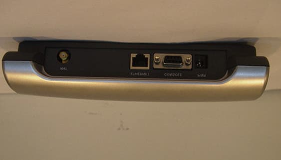
FFMLW1100AP
Nov 28, 2001WLAN Access Point
Equipment Class
DSS - Part 15 Spread Spectrum Transmitter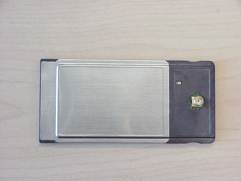
FFMLW1100N
Oct 25, 2001LP PCMCIA Card, model LW1100N
Equipment Class
DSS - Part 15 Spread Spectrum Transmitter
FFMGT-8310C
Dec 07, 2000Cordless Phone
Equipment Class
DSS - Part 15 Spread Spectrum Transmitter