GAFFRS22SPR22 Channel 2-Way Radio
Columbia Telecommunications Group Inc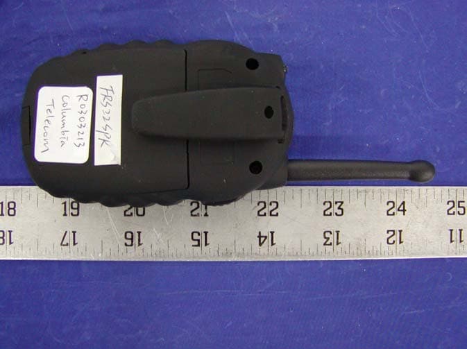
Click to zoom
Application Details
- Equipment Class
- FRF - Part 95 Family Radio Face Held Transmitter
- Date of Grant
- May 06, 2003
- Application Purpose
- Original Equipment
- Date of Application
- May 06, 2003
- Equipment Note
- 22 Channel 2-Way Radio
- Frequency Range
- 462.56250000 - 467.71250000
- Country
- United States
Documents & Files
Document Text
Text extracted from the exhibit documents filed with the FCC. Open a document above to read the original.
Users Manual
COLUMBIA OPERATIONS MANUAL FRS22SPR 22 Channel 2-Way Radios Owners Manual and Instructions SCAN CALL LOCK UP DN MENU 2 ADJUSTMENT: REPLACEMENT or substitution of transistors, regulardiodes or other parts of a unique nature, with parts other than thoserecommended by Columbia, may cause a violation of the technicalregulations of part 95 of the FCC Rules, or violation of Type Acceptancerequirements of Part 2 of the Rules.NOTE: This equipment has been tested and found to comply with thelimits for a Class B digital device, pursuant to Part 15 of the FCC RulesThese limits are designed to provide reasonable protection againstharmful interference in a residential installation. This equipmentgenerates, uses and can radiate radio frequency energy and, if notinstalled and used in accordance with the instructions, may causeharmful interference to radio communications. However, there is noguarantee that interference will not occur in a particular installation. Ifthis equipment does cause harmful interference to radio or televisionreception, which can be determined by turning the equipment off andon, the user is encouraged to try to correct the interference by one ormore of the following measures:• Reorient or relocate the receiving antenna. • Increase the separation between the equipment and receiver. • Consult the dealer or an experienced radio/TV technician for help. This device complies with Part 15 of the FCC Rules. Operation is subjectto the following condition: this device must accept any interferencereceived, including interference that may cause undesired operation. FCC Warnings 3 Contents FCC Warnings .................................................... 2 Contents .............................................................. 3Introduction ........................................................ 4 Controls and displays ...................................... 4 Component Guide .............................................. 5 Setting Up Y our FRS /GMRS Radio ................... 6 Battery Installation .......................................... 6 Battery Meter .................................................. 7Low Battery Indicator ........................................ 7 Operation ............................................................. 9 Turning on your Device .................................... 9 Communication ................................................. 9 Receiving communications ................................. 9 Respond prompt tone ...................................... 10 Channel selection ............................................ 10 Frequencies .................................................... 11 To speak directly to another radio .................... 11 Range ............................................................. 11 Calling (Paging) another radio ......................... 12 Special Features ................................................ 1 3 Automatic Squelch ........................................... 13 Monitor .......................................................... 13 Channel Lock .................................................. 14 Channel Scan .................................................. 14 Automatic Battery Save .................................... 15 External Mic/Spk/Chg Jacks ............................ 15 Built-in flashlight......................................................15 Customer Support ............................................. 1 6 Channel Frequencies and Code Charts ............ 1 7 Warranty ............................................................ 1 8 4 Included In Your PackageWhen you unpack your FRS /GMRS Radio, you should find the following items enclosed in thepackage:• 2 2 -channel FRS /GMRS unit-2PCS • • Belt-Clip (attached)-2PCS • 1.5V AAA size battery-8PCS • This manual Please check for these Items carefully. If any itemsare missing, call Columbia TelecommunicationsCustomer support at 1-800-889-7434 between 9amand 5pm EST (Eastern Standard Time).Controls and Displays1. Speaker/Mic/Charge jack2. Power Button3. Lock Button4. Menu Button5. Monitor Button6. Call Button7. PTT(Talk Button)8. Antenna9. LCD Panel10. Up Button (Change Channel and Volume)11. Down Button (Change Channel and Volume)12. Belt clip13. Flashlight Introduction COLUMBIA FRS14-SPR SCAN CALL LOCK UP DN MENU SCAN CALL LOCK UP DN MENU A A A A A A A A A A A A 5 Component Guide ChannelNumber Transmit Symbol Receive Symbol Battery Scan Level Lock SCAN Volume 2. Power Button 3. Lock Button 4. MENU B utton 5. Monitor Button 6. Call Button 7. PTT(Talk Button) 13.FlashLight 8. Antenna 9. LCD Panel 10. Up Button11. Down Button 12. Belt clip CALL LOCK UP DN MENU 1 . Speaker/Mic/charge jack Battery InstallationTo use the radio, you must install 4 AAA sizebatteries.Caution: incorrect positioning of the batteriescan damage both the batteries and the unit.To install the batteries:• Remove the belt clip by pulling the tab on the top of the belt clip back,and sliding it up and off of the unit. • Pull the battery door lock tab down to release the battery cover. • lnsert four AAA batteries. Position the batteries according to the polaritymarkings on the plastic. • Replace the battery cover. Snap the lock tab and belt clip back into place. connecting the adaptor Lift the rubber flap on the top of the unit to expose the jack. To use the unit with an AC/DC Adaptor rechargeable batteries insert the roundconnector (OD 2.5mm) of the7.5V DC/100mA AC/DC adaptor* into the SPK/MIC/CHG jack on top of the unit. Note The unit should be turned OFF in order to charge the batteries properly.If theunit is turned ON and placed forcharging the charge current is too low for the battery to charge up as the unit is Setting Up Y our /GMRS Radio Setting Up Y our F RS /GMRS Radio 6 still using power.There is no chargeindicator during charging at OFF mode.Ittakes approximately 7 to 10 hours to fullycharge the batteries if they are at the theirlowest lever. WARNINGDO NOT CHARGE THIS UNIT USING…
Text truncated - open the document above for the full version.
External Photos
APPENDIX C - EUT EXTERNAL PHOTOGRAPHS Chassis - Front View Chassis – Rear View
ID Label/Location Info
APPENDIX A - FCC ID LABELING AND LOCATION Proposed FCC ID Labeling Proposed FCC ID Location Rear Side of EUT / Proposed Label Location FCC ID: GAFFRS22SPR FCC ID: GAFFRS22SPR
Internal Photos
APPENDIX C - EUT INTERNAL PHOTOGRAPHS EUT – Solder View EUT - Component View
Operational Description
- 1 - CIRCUIT DESCRIPTION 1. RECEIVER SECTION Radio Frequency signal received by the antenna (ANT1), passing through the Low Pass Filter (L1,L3, C2-C5). The RF signal is then amplified by Low Noise Amplifier Q1 and passes through a Band Pass Filter of L16,19,C14,16,82,83. The filtered signal within the range of 462 MHz – 467 MHz is then mixed with the first local oscillator signal from the Voltage Controlled Oscillator (VCO) circuit (Q11,Q10, D7, L18) through Q3, a portion of VCO signal is then feedback to the PLL IC (IC2) for phase comparison generating a stable RX frequency, the output signal is filtered by FL2 (21.7 MHz) which is the first Intermediate Frequency (IF) and is then amplified by Q4. The IF signal is fed to the discriminator IC1 pin 16 which is then mixed with the second local oscillator supplied by crystal X1 (21.25 MHz) to produced a reduced second IF signal which is then filtered by FL3 (KTM450HTW). Demodulated signal is recovered through correct adjustment of IF tank coil (IFT1) and the internal discriminator circuit of IC1. The recovered Audio signal is outputted at pin 9 of IC1 and then processed through filtering done by Q20, the fully recovered audio signal is then further amplified by Power Amplifier IC101. An audible sound is therefore produce by the speaker SPK100, which can be varied digitally from the CPU pins 29,20,31 and the corresponding series of resistors R4,R16,R66. 2. TRANSMITTER SECTION PTT switch (SW1) when pushed triggers the Transmitter Circuit “ON”, the voice signal generates by the surrounding noise passes through the microphone MIC1 where mechanical to electrical transformation occurs, the electrical transformed signal is then filtered by Q18. The output signal is Modulated by a modulator circuit with a varactor diode D7 and L18. The external components from Q10,Q11 form a VCO Circuit which generates the required oscillating frequency for transmission, a portion of this signal is feedback to the PLL IC2 pin 14 for phase comparison in order to produce a stabilized TX frequency. The modulated signal is then amplified by a Cascaded Amplifier Circuit Q7 and Q8 and again amplified by Q5 and Q6 to produce a sufficient Radio Frequency signal emitted by the Antenna (ANT1). 3. CALL TRANSMISSION By pushing the CALL key, a signal is detected by the CPU (IC105), a CALL data is then produced by the CPU. This data passes through the Low Pass Filter Q18 and modulated by the varactor diode D7 and L18. The signal follows it’s conventional transmission section path through the antenna. - 2 - 4. BATTERY LOW DETECTION Battery Low Detection is controlled by the CPU pin 20 as detected on the LCD 1, however a voltage divider circuit R57 and R54 serve as the stabilize reference voltage for the CPU to process its detection. 5. SQUELCH DETECTION Supported by the linear IC circuit (IC1), a resistor R21 sets the level of detection and Diode D3 acts as a comparator circuit interface with the CPU. 6. POWER SUPPLY Supply voltage of 6 Volts dc is needed to power “ON” the whole circuitry, by four (4) batteries “AAA” size. FREQUENCY CHART CHANNEL FREQUENCY (MHz) CHANNEL FREQUENCY (MHz) 1 462.5625 12 467.6625 2 462.5875 13 467.6875 3 462.6125 14 467.7125 4 462.6375 15 462.5500 5 462.6625 16 462.5750 6 462.6875 17 462.6000 7 462.7125 18 462.6250 8 467.5625 19 462.6500 9 467.5875 20 462.6750 10 467.6125 21 462.7000 11 467.6375 22 462.7250
Parts List/Tune Up Info
ALIGNMENT PROCEDURE AND SPECIFICATION A. STANDARD TEST CONDITION 1. RF IN/OUT IMPEDANCE ----- 50 OHM 2. RF SIGNAL GENERATOR RF OUTPUT ----- -47dBm MODULATION ----- 1 Khz, 0.5 Khz DEVIATION 3. SPEAKER OUTPUT IMPEDANCE ----- 8 OHM 4. SPEAKER VOLUME ----- MAXIMUM 5. MIC INPUT SIGNAL ----- 1 Khz 10 mVrms 6. POWER SUPPLY ----- DC 6V +/- 15 % B. ELECTRICAL TEST ITEMS 1. VCO VOLTAGE ADJUSTMENT 1) PRESS AND HOLD DOWN THE POWER BUTTON TO POWER ON 2) PRESS THE PTT BUTTON INTO THE TX MODE 3) CONNECT THE DC VOLT METER TO TP1 4) ADJUST L18 AND OBSERVE DC VOLTAGE LIMIT : 0.8 +/- 0.3 Vdc 2. FREQUENCY ADJUSTMENT 1) CONNECT THE FREQUENCY COUNTER TO ANT POINT 2) PRESS THE PTT BUTTON 3) ADJUST THE FREQUENCY BY CV1 LIMIT : +/- 100 Hz 3. TX POWER CHECK 1) CONNECT THE RF POWER METER TO ANT POINT 2) PRESS THE PTT BUTTON 3) MEASURE THE TX POWER LIMIT : 21 dBm +/- 1 dB 4. MIC MODULATION SENSITIVITY CHECK 1) CONNECT THE MODULATION METER TO ANT. 2) THE AUDIO SIGNAL INPUT TO MIC. 3) PRESS THE PTT BUTTON 4) MEASURE THE MODULATE DEV. LIMIT : 0.9 +/- 0.3 Khz DEV . 5. MAXIMUM DEVIATION CHECK 1) CONNECT THE MODULATION METER TO ANT. 2) THE AUDIO SIGNAL INPUT TO MIC. 3) INCREASE THE AUDIO LEVEL BY 20DB 4) PRESS THE PTT BUTTON 5) MEASURE THE MODULATE DEV. LIMIT : 1.9 +/- 0.4 Khz DEV . 6. CALL SIGNAL MODULATION DEV. CHECK 1) CONNECT THE MODULATION METER TO ANT. 2) PRESS THE CALL BUTTON 3) MEASURE MODULATE DEV. LIMIT : 1.2 +/- 0.3 Khz DEV. 7. LOW BATTERY DETECT CHECK 1) VARY THE DC POWER 2) OBSERVE THE BATTERY ICON INSIDE BARS DISAPPEARED 3) MEASURE THE DC POWER VOLTAGE LIMIT : 4.4 +/- 0.2 Vdc 8. DESCRIMINATOR ADJUST 1) CONNECT THE SSG TO ANT. 2) CONNECT THE DC VOLT METER TO TP10 3) ADJUST IFT1 AND MEASURE TP10 VOLTAGE LIMIT : 1.3 +/- 0.2 Vdc 9. SPEAKER OUTPUT LEVEL CHECK 1) CONNECT THE SSG TO ANT. 2) CONNECT THE AUDIO VOLT METER TO SPK. 3) MEASURE THE SPEAKER OUTPUT LEVEL LIMIT : -1 +/- 4 dBm 10. RECEIVING SENSITIVITY CHECK 1) CONNECT THE SSG TO ANT. 2) CONNECT THE SINAD METER TO SPK. 3) REDUCE THE SSG RF OUT PUT LEVEL UP TO SINAD 12dB 4) MEASURE THE SSG RF OUTPUT LEVEL LIMIT : < -116 dBm 11. SQ CHECK 1) CONNECT THE SSG TO ANT. 2) CONNECT THE SINAD METER TO SPK. 3) CONNECT THE DC VOLT METER TO TP12 4) REDUCE THE SSG RF OUTPUT UP TO TP12 IS CHATERING 5) MEASURE THE SINAD METER LIMIT : 6 +/- 2 dB
Parts List/Tune Up Info
slc_npart descrip quantity reference ECS-1211-010A CAP_C CHIP 1PF/B/(CH)/(0603) A:COG150L 1 C82 ECS-1211-020A CAP_C CHIP 2PF/B(+/-0.15PF)/(CH)/(0603) A:COG150L 1 C16 ECS-1211-3R3A CAP_C CHIP 3.3PF/B/(CH)/(0603) A:COG150L 1 C63 ECS-1211-050A CAP_C_CHIP 5PF/B(CH)(0603) A:COG150L 1 C36 ECS-1211-5R6A CAP_C CHIP 5.6PF/B/(CH)/(0603) A:COG150L 1 C96 ECS-1212-060A CAP_C_CHIP 6PF/C(CH)(0603) A:COG150L 1 C58 ECS-1212-070A CAP_C_CHIP 7PF/C(CH)(0603) A:COG150L 2 C42,C44 ECS-1213-080A CAP_C_CHIP 8PF/D(CH)(0603) A:COG150L 3 C40,C66,C67 ECS-1213-090A CAP_C_CHIP 9PF/D(CH)(0603) A:COG150L 1 C35 ECS-1213-100A CAP_C_CHIP 10PF/D/(CH)/(0603) A:COG150L 8 C2,C8,C9,C61,C64,C83,C89,C312 ECS-1213-120A CAP_C CHIP 12PF/D/(CH)/(0603) A:COG150L 4 C18,C39,C52,C62 ECS-1213-150A CAP_C CHIP 15PF/D/(CH)/(0603) A:COG150L 1 C5 ECS-1216-220A CAP_C_CHIP 22PF/J(CH)(0603) A:COG150L 6 C4,C14,C20,C27,C56,C76 ECS-1216-300A CAP_C_CHIP 30PF/J(CH)(0603) A:COG150L 1 C51 ECS-1216-470A CAP_C_CHIP 47PF/J(CH)(0603) A:COG150L 2 C7,C17 ECS-1216-680A CAP_C_CHIP 68PF/J(CH)(0603) A:COG150L 1 C50 ECS-1216-101A CAP_C_CHIP 100PF/J(CH)(0603) A:COG150L 3 C37,C49,C149 ECS-1216-221A CAP_C_CHIP 220PF/J(CH)(0603) A:COG150L 2 C87,C134 ECS-1216-471A CAP_C_CHIP 470PF/J(CH)(0603) A:COG150L 7 C1,C10,C12,C31,C41,C43,C54 ECS-2297-102A CAP_C_C.H.D. B0.001uF/K(0603) X:X7R282L 19 C21,C28,C32,C33,C60,C68,C69,C71,C74,C85,C86,C91 ECS-2297-102A CAP_C_C.H.D. B0.001uF/K(0603) X:X7R282L 0 C123,C205,C302,C308,C309,C310,C90 ECS-2297-103A CAP_C_C.H.D. B0.01uF/K(0603) X:X7R282L 13 C11,C15,C59,C65,C72,C75,C77,C79,C80,C81,C92,C301,C38 ECS-2297-223A CAP_C_C.H.D. B0.022uF/K(0603) X:X7R282L 2 C88,C136 ECS-2297-333A CAP_C_C.H.D. B0.033uF/K(0603) X:X7R282L 1 C107 ECS-2297-473A CAP_C_C.H.D. B0.047uF/K(0603) X:X7R282L 4 C22,C34,C45,C70 ECS-22A8-104A CAP_C_C.H.D. F0.1uF/M(0603) Y:YF153L 22 C3,C6,C19,C23,C25,C26,C30,C46,C53,C55,C78,C84,C100 ECS-22A8-104A CAP_C_C.H.D. F0.1uF/M(0603) Y:YF153L 0 C104,C111,C115,C116,C121,C305,C502,C47,C106 ECS-22A9-105A CAP_C_C.H.D. F1uF/Z(0603) Y:YF153L 4 C29,C57,C137,C140 ECC-6300-060A CAP_C_TRIMMER 6PF 1 CV1 ECT-1133-100A CAP_T_CHIP 10uF/M/10V(3.2X1.6) 1 C73 ECE-2112-101A CAP_E_MINI 100uF/6.3V(D4XL7) 5 C48,C101,C103,C112,C144 ECE-2012-101F CAP_E_MINI 100uF/6.3V(D5XL5) 1 C24 EHS-0250-001A CHIP COIL SPRING 0.32-1.2-3T 3 L1,L3,L9 EHS-0250-002A CHIP COIL SPRING 0.32-1.2-4T 3 L4,L11,L18 EHS-0122-100A CHIP COIL SQUARE 10nH/J(0603) 2 L5,L10 EHS-0123-180A CHIP COIL SQUARE 18nH/K(0603) 1 L202 EHS-0123-220A CHIP COIL SQUARE 22nH/K(0603) 5 L2,L6,L13,L14,L301 EHS-0122-270A CHIP COIL SQUARE 27nH/J(0603) 2 L16,L19 EHS-0122-390A CHIP COIL SQUARE 39nH/J(0603) 1 L12 EHS-0123-222A CHIP COIL SQUARE 2.2uH/K(0603) 1 L8 ERS-0224-000A RES_(0603)-10 0 OHM 1 R32 ERS-0224-100A RES_(0603)-10 10 OHM 5 R33,R37,R42,R52,R105 ERS-0224-220A RES_(0603)-10 22 OHM 1 R59 ERS-0224-330A RES_(0603)-10 33 OHM 2 R20,R28 ERS-0224-390A RES_(0603)-10 39 OHM 2 R7,R8 ERS-0224-560A RES_(0603)-10 56 OHM 3 R41,R62,R168 ERS-0224-680A RES_(0603)-10 68 OHM 1 R48 ERS-0224-820A RES_(0603)-10 82 OHM 1 R14 ERS-0224-101A RES_(0603)-10 100 OHM 2 R3,R5 ERS-0224-121A RES_(0603)-10 120 OHM 1 R401 ERS-0224-151A RES_(0603)-10 150 OHM 2 R36,R51 ERS-0224-471A RES_(0603)-10 470 OHM 1 R2 ERS-0224-561A RES_(0603)-10 560 OHM 1 R167 ERS-0224-102A RES_(0603)-10 1 KOHM 6 R38,R39,R40,R56,R151,R153 ERS-0224-182A RES_(0603)-10 1.8 KOHM 1 R23 ERS-0224-222A RES_(0603)-10 2.2 KOHM 7 R27,R31,R45,R46,R58,R154,R65 ERS-0224-332A RES_(0603)-10 3.3 KOHM 1 R13 ERS-0224-392A RES_(0603)-10 3.9 KOHM 1 R149 ERS-0224-472A RES_(0603)-10 4.7 KOHM 9 R11,R43,R50,R61,R74,R162,R163,R166,R301 ERS-0224-682A RES_(0603)-10 6.8 KOHM 6 R25,R47,R60,R102,R66,R77 ERS-0224-103A RES_(0603)-10 10 KOHM 12 R9,R10,R26,R34,R44,R49,R55,R68,R70,R71 ERS-0224-103A RES_(0603)-10 10 KOHM 0 R139,R140 ERS-0224-183A RES_(0603)-10 18 KOHM 3 R1,R30,R402 ERS-0224-223A RES_(0603)-10 22 KOHM 2 R29,R67 ERS-0224-473A RES_(0603)-10 47 KOHM 10 R12,R15,R54,R63,R146,R161,R164,R165,R302,R76 ERS-0224-823A RES_(0603)-10 82 KOHM 1 R19 ERS-0224-104A RES_(0603)-10 100 KOHM 1 R53 ERS-0224-224A RES_(0603)-10 220 KOHM 1 R137 ERS-0224-334A RES_(0603)-10 330 KOHM 1 R22 ERS-0224-474A RES_(0603)-10 470 KOHM 1 R69 ERS-0224-564A RES_(0603)-10 560 KOHM 1 R64 ERS-0224-684A RES_(0603)-10 680 KOHM 2 R6,R150 ERS-0224-105A RES_(0603)-10 1 MOHM 2 R24,R35 ERS-0224-335A RES_(0603)-10 3.3 MOHM 1 R57 EFT-1420-001A CRYSTAL FILTERS 21.7MHz 1 FL2 EFT-2120-004A CERAMIC FILTER 450+/-3K CFM450HTW 1 FL3 EIF-0102-014A IFT COIL 450KHz-5.7mm 1 IFT1 EXR-1420-007A XTAL_21.250MHz(18PF)HC-49S(3.6mm)+/-5PPM(-10~+60) 1 X1 EXR-2280-001A CERAMIC XTAL_3.58MHz 1 X2 SDD-1109-001A DIODE_SW KDS114(URP) 3 D1,D4,D8 SDD-1207-001A DIODE_SW LL4148/MM4148 MELF 7 D2,D3,D5,D6,D9,D10,D13 SZD-0204-8R2A DIODE_ZEN. BZX55C8V2(8.2V/0.5W) 1 ZD1 SDD-4008-001B DIODE_VAR KDV154C(USC) 1 D7 STR-2213-001A TR_RF POWER 2SC4988(SOT-89) 2 Q5,Q6 STR-2306-003A TR_RF 2SC4901 (SOT-23) HFE:120-250 6 Q1,Q3,Q7,Q8,Q10,Q11 STR-2306-001A TR_RF KTC3880Y SOT23 1 Q4 STR-1206-003A TR_SW KRC103SY(SOT-23) 1 Q16 STR-1106-001A TR_SS KST2907TF/KTN2907S/AS /MMBT2907LT1(SOT-23) 3 Q12,Q13,Q14 STR-1206-002A TR_SW KTA1298(SOT-23) 2 Q2,Q21 STR-1306-001B TR_SS KTC3875Y (SOT-23) 8 Q9,Q15,Q17,Q18,Q19,Q20,Q22,Q23 SIC-2103-007A IC_LI KB8825/8825B (16-TSSOP-0044) 1 IC2 SIC-2103-008A IC_LI KA386/LM386(SOP) 1 IC101 SIC-2103-001A IC_LI KA3361/MC3361D/SIT336101-S0B0 (SOP) 1 IC1 SLD-3015-001A LED CHIP GREEN LTST-C150GKT (1206) 1 LED3 SLD-1016-001A LED BLUE SF-50TB34 1 LED2 ESW-2112-006A TACK SWITCH IT-1101VLA-3180 1 PTT EJK-5200-004A EARPHONE JACK ST-102-06 FX-10 1 JACK1 MMT-0500-016A SHIELD COVER 15.7X15.2X2.5mm TIN-2.0mm 1 VCO CAN MMT-0500-081A SHEET COPPER 10X8X0.1mm 1 SLD-0000-002A LCD GS-8836-TFHW 1 MMT-1400-012A LCD BRACKET 25.8X19.4X9.3(mm)-T0.3mm 1 MFB-0600-051A ZEBRA BAR 17.5X5.4X1.6mm 1 MPF-1400-022A HOLDER_FRS14-SPR LCD ACRYL 1 BBM-B061-408A PCB_BM DS+GOLD GMRS22-SPR BASIC REV:01 1 PCB SIC-1213-001A IC_uP XC6201P402MR (SOT-25) 1 IC3 SIC-1210-016A IC_uP ITC-FSPB210N4M1A O.T.P (DI…
Text truncated - open the document above for the full version.
Schematics
spr22basic.SCH-1 - Tue Mar 18 09:14:46 2003
Test Report
Note: This test report is specially limited to the above client company and product model. It may not be duplicated without prior written consent of Bay Area Compliance Laboratory Corporation. This report must not be used by the client to claim product endorsement by NVLAP or any agency of the U.S. Government. . FCC PART 95 EMI MEASUREMENT AND TEST REPORT For Columbia Telecommunications Group Inc. 174 Milbar Blvd. Farmingdale, NY 11375 FCC ID: GAFFRS22SPR 2003-04-19 This Report Concerns: Original Report Equipment Type: FRS & GMRS Test Engineer: Benjamin Jing / Report Number: R0303213 Test Date: 2003-04-14 Reviewed By: Hans Mellberg / Prepared By: Bay Area Compliance Laboratory Corporation 230 Commercial Street Sunnyvale, CA 94085 Tel: (408) 732-9162 Fax: (408) 732 9164 Columbia Telecommunications Group Inc. FCC ID: GAFFRS22SPR Report # R0303213Rpt.doc FCC Part 95 Test Report Page 2 of 24 TABLE OF CONTENTS 1 - GENERAL INFORMATION..................................................................................................................................4 1.1 PRODUCT DESCRIPTION FOR EQUIPMENT UNDER TEST (EUT) ..............................................................................4 1.2 OBJECTIVE.............................................................................................................................................................4 1.3 RELATED GRANT/SUBMISSION...............................................................................................................................4 1.4 TEST METHODOLOGY............................................................................................................................................4 1.5 TEST FACILITY.......................................................................................................................................................4 1.6 TEST EQUIPMENT LIST...........................................................................................................................................5 2 - SYSTEM TEST CONFIGURATION.....................................................................................................................6 2.1 JUSTIFICATION.......................................................................................................................................................6 2.2 EUT TEST CONFIGURATION..................................................................................................................................6 2.3 SPECIAL ACCESSORIES...........................................................................................................................................6 2.4 SCHEMATICS / BLOCK DIAGRAM...........................................................................................................................6 2.5 EQUIPMENT MODIFICATIONS.................................................................................................................................6 2.6 CONFIGURATION OF TEST SYSTEM.........................................................................................................................7 2.7 TEST SETUP BLOCK DIAGRAM...............................................................................................................................7 3 - REQUIREMENTS OF PROVISIONS ...................................................................................................................8 3.1 REQUIREMENTS AND TEST SUMMARY...................................................................................................................8 3.2 LABELING REQUIREMENT......................................................................................................................................8 4 - EFFECTIVE RADIATED POWER.......................................................................................................................9 4.1 PROVISION APPLICABLE.........................................................................................................................................9 4.2 TEST PROCEDURE..................................................................................................................................................9 4.3 TEST EQUIPMENT.................................................................................................................................................10 4.4 TEST RESULTS.....................................................................................................................................................10 5 - MODULATION CHARACTERISTICS ..............................................................................................................11 5.1 PROVISION APPLICABLE.......................................................................................................................................11 5.2 TEST PROCEDURE................................................................................................................................................11 5.3 TEST EQUIPMENT.................................................................................................................................................11 5.4 TEST RESULTS.....................................................................................................................................................11 6 - OCCUPIED BANDWIDTH OF EMISSION.......................................................................................................13 6.1 PROVISION APPLICABLE.......................................................................................................................................13 6.2 TEST PROCEDURE................................................................................................................................................13 6.3 TEST EQUIPMENT.............................................................................................................................................…
Text truncated - open the document above for the full version.
Test Setup Photos
APPENDIX B - TEST SETUP PHOTOGRAPHS Radiated Emission - Front View Radiated Emission - Rear View
Contact Information
Applicant
David Giladi(President)
Test Firm
Bay Area Compliance LaboratoryJohn Chan
Technical Specifications
| # | Rule Parts | Frequency Range | Power Output | Emission | Tolerance |
|---|---|---|---|---|---|
| 2 | 95B | 462.5625 MHz - 467.7125 MHz | 54.00 mW | 11K0F3E | 2.5 ppm |
Other Applications from Columbia Telecommunications Group Inc
GAFMIC2
Aug 01, 2004Wireless Microphone
Equipment Class
DXX - Part 15 Low Power Communication Device Transmitter
GAFRC16FF27
Jun 29, 2004Remote Control Toy Transmitter
Equipment Class
DXX - Part 15 Low Power Communication Device Transmitter
GAFRC16SM27
Jun 06, 2004Remote Control Toy Transmitter
Equipment Class
DXX - Part 15 Low Power Communication Device Transmitter
GAFFR22-NL
Jan 29, 200422 Channels 2 Way Radio
Equipment Class
FRF - Part 95 Family Radio Face Held Transmitter
GAFWT-SD2
Oct 06, 2003Walkie Talkie
Equipment Class
DXX - Part 15 Low Power Communication Device Transmitter