GB8DM855UHF Pulsed L Band TRX
Honeywell International Inc.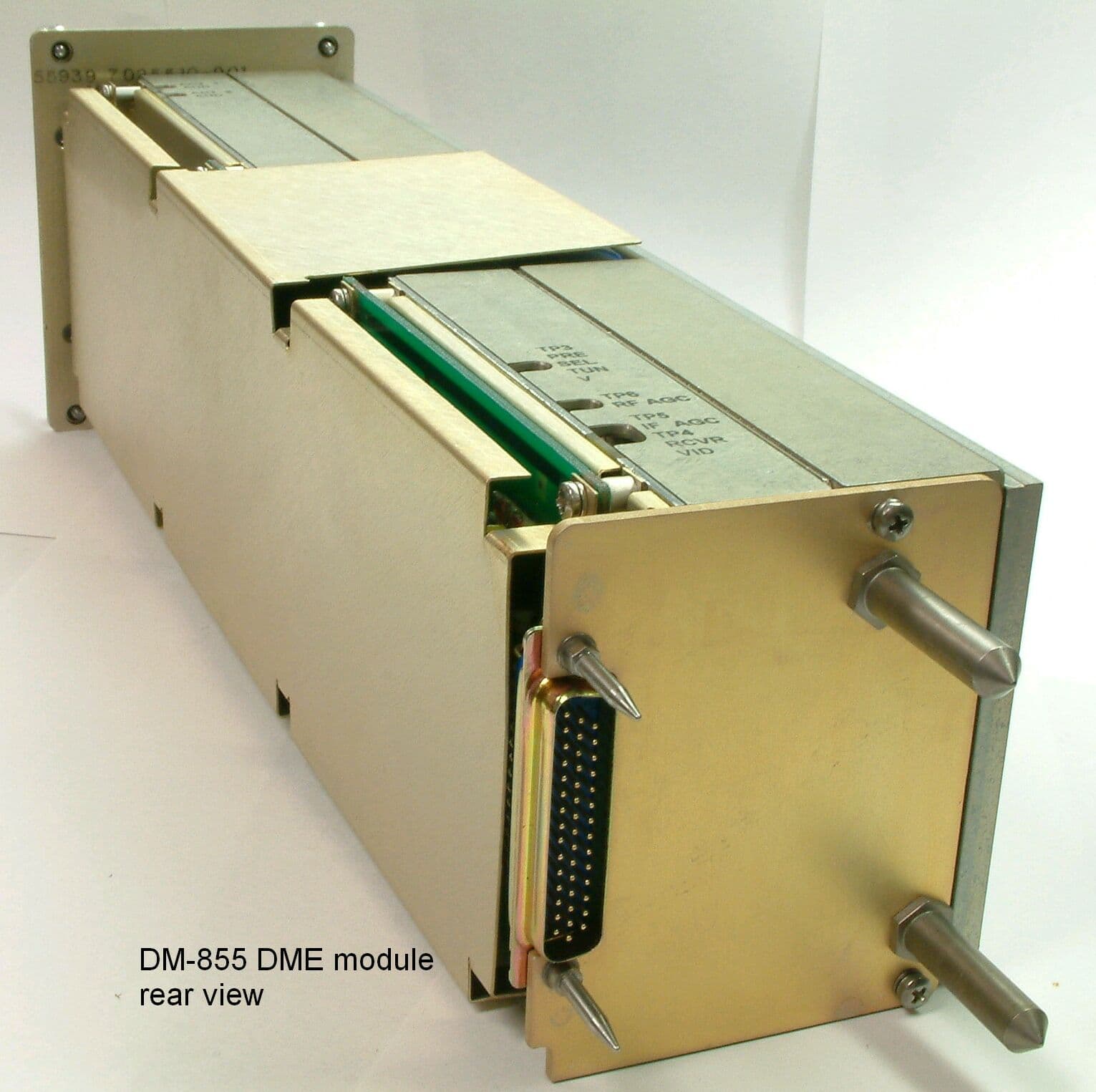
Click to zoom
Application Details
- Equipment Class
- TNB - Licensed Non-Broadcast Station Transmitter
- Date of Grant
- Mar 12, 2003
- Application Purpose
- Original Equipment
- Date of Application
- Nov 25, 2002
- Equipment Note
- UHF Pulsed L Band TRX
- Frequency Range
- 1025.00000000 - 1150.00000000
- Company
- Honeywell International Inc.
- Country
- United States
Documents & Files
Document Text
Text extracted from the exhibit documents filed with the FCC. Open a document above to read the original.
Users Manual
OPERATING MANUAL 2B-09-00 Page 2 Nov 15/02 DIGITAL AUTOMATIC FLIGHT CONTROL SYSTEMS 1. MCDU Controls The radio tuning function is operated using a subset of the controls available on the MCDU, shown in Figure 31. DNEXT and PREV Function Keys-- NEXT and PREV function keys move to adjacent pages where more than one page of the same title is used DRADIOFunction Key-- The RADIO function key activates the radio tuning function and displays the RADIO 1/2 page, DTuning Knob-- The tuning knob is used to dial infrequencies orother numeric values. Figure 31 OPERATING MANUAL 2B-09-00 Page 3 Nov 15/02 DIGITAL AUTOMATIC FLIGHT CONTROL SYSTEMS 2. Page Organization The radio tuning function is accessed via the RADIO function key on the MCDU, which displays the RADIO 1/2 page. All other pages are accessed from RADIO 1/2 using the line select keys or the NEXT and PREV function keys, shown in Figure 32. Figure 32 Movement between the RADIO 1/2 and RADIO 2/2 pages is done with the NEXT and PREV function keys, while access to the COM DETAIL, TCAS/XPDR, and NAV DETAIL pages is via line select keys from RADIO 1/2 and access to the HF DETAIL, MLS DETAIL, and ADF DETAIL pages are via line select keys from RADIO 2/2. OPERATING MANUAL 2B-09-00 Page 4 Nov 15/02 DIGITAL AUTOMATIC FLIGHT CONTROL SYSTEMS 3. MCDU Tuning Description Allofthepages thatcorrespond toa particularradio type(e.g., VHFcommunications orADF) are arranged as shown in Figures 33,34, and35, andtypically consistof adetails pagealong with two memory pages. The details pages allow the specific features of each radio to be configured and provide access to the memory pages associated with each radio type. Figure 34 shows the pages associated with the VHF communications radios. Figure 33 OPERATING MANUAL 2B-09-00 Page 5 Nov 15/02 DIGITAL AUTOMATIC FLIGHT CONTROL SYSTEMS Figure 34 shows the pages associated with the VHF navigation radios. Figure 34 Figure 35 shows the pages associated with the TCAS/transponder subsystem Figure 35 OPERATING MANUAL 2B-09-00 Page 6 Nov 15/02 DIGITAL AUTOMATIC FLIGHT CONTROL SYSTEMS Figure 36 shows the arrangement of pages associated with the high--frequency (HF) communications radios. Figure 36 OPERATING MANUAL 2B-09-00 Page 7 Nov 15/02 DIGITAL AUTOMATIC FLIGHT CONTROL SYSTEMS Figure 37 shows the page associated with the automatic direction finder (ADF). Figure 37 OPERATING MANUAL 2B-09-00 Page 8 Nov 15/02 DIGITAL AUTOMATIC FLIGHT CONTROL SYSTEMS Figure 38 shows the pages associated with the Microwave Landing System (MLS) receiver. Figure 38 The RADIO MENU is used for manually tuning the radios. Pushing the RADIO key on the MCDU displays the RADIO MENU page 1/2. OPERATING MANUAL 2B-09-00 Page 9 Nov 15/02 DIGITAL AUTOMATIC FLIGHT CONTROL SYSTEMS 2B--09--20: BASIC OPERATION In keeping with the titling and numberingconventions usedby MCDU functions, eachMCDU page is arranged with a centered title at the top and a page number in the upper--right corner. Page numbers are formatted as the current page number (among those with the same page title), a slash î/î, and the number of pages with the same title. For example, there are two pages entitled îRADIO,î the first is labeled RADIO 1/2, as shown in Figure 39, and the second RADIO 2/2. The bottom line on each page displays the characters entered on the MCDU keypad and is called the scratchpad. The scratchpad is shared across all MCDU client functions,and is not under the control of the radio tuning function. The text area adjacent to each line select key (LSK) on the MCDU is referred to as a field, and identified by the LSK it is associated with. For example, the active frequency for VHF COM radio 1 (shown as COM1, 123.200) on the RADIO 1/2 page is in field 1L. Figure 39 OPERATING MANUAL 2B-09-00 Page 10 Nov 15/02 DIGITAL AUTOMATIC FLIGHT CONTROL SYSTEMS Pushing the NEXT or PREV key when this page is displayed displays the RADIO MENU page 2/2, shown in Figure 40. Figure 40 When the scratchpad is empty, pushing a line select key either moves the format cursor to the adjacent field, or performs the function indicated by the icon that appears near the key. The icons and their functions are described below. îSwapî frequencies. This symbol indicates that exchanges between the active and preset frequencies for the associated radio can be made. This has the effect of saving the currently active frequency in the preset memory, and tuning the radio to the frequency previously stored as the preset. Page indicator. When this icon is displayed, pushing the adjacent LSK changes the display to another page. The page to be displayed is eitherlabeled explicitly or itis adetail page for the radio in the associated field. OPERATING MANUAL 2B-09-00 Page 11 Nov 15/02 DIGITAL AUTOMATIC FLIGHT CONTROL SYSTEMS Exclusive selection. This icon is displayed next to a list of mutually exclusive options. Each time the adjacent LSK is pushed, the next options become selected, wrapping around to the first when the last option is reached. The selected value is displayed in the active color (greenin this document) and large font, while the other selection are displayed as smaller, whitecharacters. Immediate function. This icon indicates that the function identified in the field will be carried outimmediately whenthe adjacent LSK key is pushed. Copy value. This icon is used on the memory pages to indicate that the frequency highlighted by the format cursor will be copied into the active frequency for the associated radio. Format cursor. The cursor box highlights the value in the currently active field. Tuning curl. This icon indicates that the data value highlighted by the format cursor can be changed by turning the MCDU tuning knob. OPERATING MANUAL 2B-09-00 Page 12 Nov 15/02 DIGITAL AUTOMATIC FLIGHT CONTROL SYSTEMS IfLSK2R,thesecond onthe righthand side,shown inFigure 41,is pushed,the formatcursor and tuning curl move from the 2L field (COM1) to field 2R (COM2). Likewise, pushing LSK 3L moves the format cursor to…
Text truncated - open the document above for the full version.
Users Manual
OPERATING MANUAL 2B-09-00 Page 39 Nov 15/02 DIGITAL AUTOMATIC FLIGHT CONTROL SYSTEMS 1. ADF Memory As with the other radio types, the radio tuning function supports 12 ADF memories displayed on two pages. In addition to entering or dialing--in frequencies for each memory, a text label of up to 8 characters may be entered for each stored frequency. The default label for each memory is îMEMORYî, a dash, and the memory number, with the memory number always on the outboard edge of the display. The ADF Memory page is described below. Labels areenteredby typinginto thescratchpad andpushing theLSK adjacentto thedesired frequency. If the radio tuning function determines that the entry is a valid frequency for the radio, the entry is accepted into the frequency field. If not, the entry is considered a label and is entered into the label field above the frequency. A label canbe replacedby makinganother scratchpad entry into a memory field, or by pushing the DEL key. Pushing the DEL key places the text îDELETEî in the scratchpad and, when entered on a memory field, deletes the associated text label, returning itto thedefault. Ifthe DELkey is used ona memory where there is no user--entered label, the frequency is deleted from memory. Access to the ADF MEMORY 2/2 page is via the NEXT and PREV function keys. OPERATING MANUAL 2B-09-00 Page 40 Nov 15/02 DIGITAL AUTOMATIC FLIGHT CONTROL SYSTEMS This section displays and controls the Active ADF frequency on the selected radio (the field title will reflect which radio was selected). Pushing LSK 1L copies the field containing the format cursor into the active frequency and moves the previously active frequency into the preset field (not shown on this page). A scratchpad entry into the field replaces the preset frequency with the previous active frequency. These sections display the ADF memories 1--3 (7--9 on ADF MEMORY 2/2). These sections display the ADF memories 4--6 (10--12 on ADF MEMORY 2/2). Pushing this LSK displays ADF detail page. Pushing this LSK displays the RADIO 2/2 page. OPERATING MANUAL 2B-09-00 Page 41 Nov 15/02 DIGITAL AUTOMATIC FLIGHT CONTROL SYSTEMS 2B--09--70: MLS1 PAGE The MLS page, shown in Figure 43, shows the currently tuned procedure and a preset, azimuth and back--azimuth, and glidepath angle, and allows setting of the operating mode (automatic/manual) and azimuth selection (azimuth or back--azimuth). It also provides access to the MLS memory pages. Figure 43 Unlike the detail pages for the other radios, the MLS page does not support the fast memory tuning operation in field 3L. OPERATING MANUAL 2B-09-00 Page 42 Nov 15/02 DIGITAL AUTOMATIC FLIGHT CONTROL SYSTEMS 1. MLS Memory Pages The MLS memory pages,FINISH THIS SECTION Figure 44 OPERATING MANUAL 2B-09-00 Page 43 Nov 15/02 DIGITAL AUTOMATIC FLIGHT CONTROL SYSTEMS 2B--09--80: RADIOINTERACTIONS The MCDU radio tuning function communicates with the radio units using a bi--directional protocol. The radio tuning function expects to receive an acknowledgement when the radio is successful in completing each tuning command. A typical interaction begins with the user entering or dialing in a new frequency for a radio. The MCDU sends the appropriate tuning command to the specified radio and awaits confirmation. If no confirmation is received within the timeout period, the frequency display on the page is changed toamberand a scratchpad message is issued as shown in Figure 45). Figure 45 The pilot can attempt to tune the radio again, in the event that the fault was transient or has been cleared by crew action. This is also important in the event that the radio is receiving the command and is, in fact, tuning the radio, but is unable to respond to the MCDU. OPERATING MANUAL 2B-09-00 Page 44 Nov 15/02 DIGITAL AUTOMATIC FLIGHT CONTROL SYSTEMS 2B--09--90: ANNUNCIATIONMESSAGES 1. RADIO 1/2 Annunciations A variety of annunciations appear on the radio tuning pages, many of which are shown in Figure 46. Figure 46 OPERATING MANUAL 2B-09-00 Page 45 Nov 15/02 DIGITAL AUTOMATIC FLIGHT CONTROL SYSTEMS Table 33 describes the annunciators on RADIO 1/2. AnnunciatorDescription 25K Indicates that the associated VHF COM radio is set to 25KHz frequency spacing. When not present, the radio is tuning with 8.33KHz frequency spacing. DME H xxx This alert Indicates that the VHF navigation radio is tuning the corresponding DME receiver independently of the primary navigation frequency. IHBT This annunciator Indicates that tuning of the radio is inhibited, usually from a remote source (such as an emergency tuning function). MICSTK Indicates that the microphone button on the radio has been down long enough that the radio has identified it as îstuckî inthe transmit position. SQ This annunciator Indicates that the squelch feature for the radio is active. TX This annunciator Indicates that the radio is currently transmitting. RADIO 1/2 Annunciator Descriptions Table 33 OPERATING MANUAL 2B-09-00 Page 46 Nov 15/02 DIGITAL AUTOMATIC FLIGHT CONTROL SYSTEMS 2. RADIO 2/2 Annunciations A variety of annunciations appear on the radio tuning pages, many of which are shown in in Figure 46. Figure 47 OPERATING MANUAL 2B-09-00 Page 47 Nov 15/02 DIGITAL AUTOMATIC FLIGHT CONTROL SYSTEMS Table 34 describes the annunciators on RADIO 2/2. AnnunciatorDescription ANT The ADF radio is in antenna mode. ARM An MLS procedure is armed. BFO The ADF radio is operating in BFO mode. CW This annunciator Indicates that the radio is currently transmitting. IHBT Indicates that tuning of the radio is inhibited, usually from a remote source (such as an emergency tuning function). In the case of two HF radios sharing a single antenna, transmitting and/orreceivingmay beinhibitedperiodically whenthe otherHF radio has recently performed a transmit operation. ITU This annunciator Indicates that the radio is currently transmitting. LO The radio is set to low squelch. M An MLS parameter has been set manually. MED The radio is set to medium squelch. RX Indicates th…
Text truncated - open the document above for the full version.
Block Diagram
mA A w m o w u o N I (n w rX 1 0 G I 1 0 m -lm 1 1 1 n< -G=l- - r---- MmiiuaxmTmlm,h ( 1 - R& k c3- CUILT-!?4 ~05G Kmi2!m =1.FT= (1+%!%-%%1 _-— T \ ----.-. M ‘1“-’“-”-=/1;1II . r n m <=’ r- 1
Cover Letter(s)
FCC ID: GB8DM855 MFA p02a0005, d02b0003 Date of Report: November 1, 2002 Date of Submission: November 25, 2002 Federal Aviation Administration Spectrum Engineering Division ASR-1 800 Independence Ave. S.W. Washington, D.C. 20591 Attention: George Sakat Applicant: Honeywell International Inc. Commercial Electronic Systems - Phoenix FCC ID: GB8DM855 FCC Rules: 87 Gentlemen: As required under FCC Rule Part 87.147(d) please consider this letter, sent on behalf of the Applicant, as notification of the filing of an application Form 731 for the certification of the referenced equipment. Attached for your records, please find: 1. copy of the FCC Application Form 731 and full Test Data Report 2. copy of the proof of electronic filing to FCC with EA# 3. copy of the covering letter to the Commission 4. copy of the Agent Authorization letter for the writer to act on behalf of the Applicant. We trust the enclosed complies with your requirements. Should you need any further clarification, kindly contact the writer. Sincerely yours, Morton Flom, P. Eng. MF/cva enclosure(s) cc: Applicant cc: FCC via Electronic Filing cc: Industry Canada VIA CERTIFIED MAIL
Operational Description
Theory of Operation DME unit, DM- 855 Emission type 850KLOD FCC Identifier: GB8DM855 The DM-855 DME Assembly (Interrogator) is a six-channel scanning unit that tracks four selected distance measuring equipment (DME) channels simultaneously. The Interrogator has two additional preset channels that provide an identification (IDENT) code when selected as active. The Interrogator measures the elapsed time of a pulse transmission to determine distance from a ground station. The Interrogator transmits in the frequency band of 1025 to 1150 Mhz with an emission type of 850KLOD, with a typical output power of 400 watts. The unit has a capability of 352 X, W, Y, Z, MLS compatible VOR/LOC or MLS paired channels. The unit is capable of operation from Sea Level to 70,000 ft. The digital range accuracy is .05 nm +/-0.1% of range with an analog accuracy of 0.3nm +/- 1% of range. The unit has a range capability of 0.0 to 300 nm and a range tracking rate from 0.0 to 999 knots, and has a velocity accuracy +/-1% or +/- 1.0 knot. The unit has a velocity acquisition time within 10% in 10 seconds and a velocity output range from 0.0 to 999 knots with a time to station capability of 0 to 999 minutes. The DME transmitter is comprised of a low level stage, followed by a stage utilizing class A to a stage using a class AB biased amplifier. It then goes to a class C common base transistor stage where the output is 5 ½ to 6 ½ watts on the first transistor, 35 watts on the second transistor and 150 watts applied to a power splitter to each of the two output stages. The output stage is a common base matched pair of transistors that each handle ½ of the output power and allowing for one transistor failure, and can allow the transmitter to still output 75 watts in the event there was an output transistor failure. Nominal output would be typically 400 watts. The Interrogator module will still interrogate ground stations at long distances with a single transistor stage failure.
Parts List/Tune Up Info
OPERATING MANUAL 2B-09-00 Page 1 Nov 15/02 DIGITAL AUTOMATIC FLIGHT CONTROL SYSTEMS RADIO TUNING AND AUDIO PANEL 2B--09--10: OVERVIEW The radio function in the Planeview was developed, using the Multifunction Control Display Unit (MCDU) for the EPIC radio tuning function. Thesystem is designed to have a radio tuning function that matched, as closely as possible, the behavior of the Honeywell Radio Management Unit (RMU) and the Rockwell Collins Radio Tuning Unit (RTU). The resulting design is described below. Throughout this document the screen images presented make minimal use of color on the display. This document describes a generic color set in which greenis used to indicate active values versus whitefor normal text, whileamberandredareusedtodrawthe crewís attention or to provide warnings. It assumed that the reader is familiar with the general characteristics of the MCDU and basic radio operations (e.g., active/preset frequency tuning, frequency spacing and formats, DME HOLD, and the unique characteristics and controls of the various types of communications and navigation radios).
Parts List/Tune Up Info
ENGINEERING SPECIFICATION SECURITY NOTATION DOCUMENT TYPE ENGINEERING BULLETIN DIVISION DEPARTMENT NO. BCAS 5892 TITLE SPEC NO. CAG E CODE IT7510184 55939 THIS TITLE PAGE CONTAINS PROPRIETARY AND DATA RIGHTS NOTATIONS. CLASS INITIAL RELEASE DATE A 4 SEP 87 CONTRACTNO. PRODUCT LINE NO. DM-850 INTEGRATED TEST SPECIFICATION FOR DM-850 PART NO. 7510184-9XXAND DM-855, PART NO. 7510184-855 AE REV LTR APPROVED BY: DATE REFAWAEBIPSAEB NO. CHECKER PRODUCT DESIGN CHECKER (FOR REF, SPCL CONT PER EPM 1.A-40) COGNIZANCE OF QE SUPVR (FOR REF, SPCL CONT PER EPM 1-A-40) FOR PAGE INDEX, SEE PAGE CR-2. REVISION RECORD FOLLOWS PAGE INDEX. THIS IS AN ELECTRONIC FACSIMILE OF THE CR-1 ON FILE WITH DOCUMENT CONTROL. PROPRIETARY NOTICE THIS DOCUMENT AND THE INFORMATION DISCLOSED HEREIN ARE PROPRIETARY DATA OF HONEYWELL INC. NEITHER THIS DOCUMENT NOR THE INFORMATION CONTAINED HEREIN SHALL BE REPRODUCED, USED, OR DISCLOSED TO OTHERS WITHOUT THE WRITTEN AUTHORIZATION OF HONEYWELL INC. NOTICE FREEDOM OF INFORMATION ACT (5 USC 552) AND DISCLOSURE OF CONFIDENCE INFORMATION GENERALLY (18 USC 1905) THIS DOCUMENT IS BEING FURNISHED IN CONFIDENCE BY HONEYWELL INC. THE INFORMATION DISCLOSED HEREIN FALLS WITHIN EXEMPTION (b) (4) OF 5 USC 552 AND THE PROHIBITIONS OF 18 USC 1905. Copyright 1999 Honeywell Inc. All Rights Reserved Hone ell AW/CRITICAL NOTATION SECURITY NOTATION 15101-000 (REV 970213 BCAS ASF5900/ENG_SPEC.DOT) (NEW lI1/99-OFC97-LOGISTLCSIBCAS) HONEYWELL INC, TITLE PAGE CR-1 PAGE APPROVED FOR SCM DATE PREPARED BY: DATE L. J. AIIocco 9/3/87 APPROVED FOR SQA DATE APPROVED BY TECHNICAL DATE MANAGER R. Fuller 9-3-87 APPROVED BY ENGINEERING DATE DEPARTMENT MANAGER C. Cunningham 9-3-87 ENGINEERING SPECIFICATION SECURITY NOTATION SPEC NO. IT7510184 AE CAGE CODE 55939 REV LTR SEE THE TITLE PAGE FOR PROPRIETARY AND DATA RIGHTS NOTATIONS. THE LATEST REVISION OF EACH SHEET IS INDICATED ON THE PAGE INDEX. Rev Page Ltr Rev Rev Rev Rev Page Ltr Page Ltr Page Ltr Page Ltr Title 30 V 31 AE CR-1 AE 32 V Page Index 33 V 34 AE CR-2 AE 35 V Revision 36 V Record 37 V 38 V CR-3 AE 39 V 4O V Table of 41 AE Contents 42 AD i AA 43 AD ii AA 44 V 45 V 1 Y 46 V 2 AE 47 V 3 AE 48 AB 4 AE 49 V 5 V 50 V 6 V 51 AE 7 V 8 V 9 V Appendix A A-0 V 10 V A-1 V 11 V 12 V 13 V Appendix B B-0 V 14 V B-1 V 15 V B-2 V 16 V B-3 AE 17 V B-4 V 18 V B-5 V 19 V B-6 V 20 V B-7 V 21 V B-8 V 22 V B-9 W 23 AE B-10 V 24 V B-11 V 25 V 26 V 27 V Appendix C C-0 V 28 V C-1 AD -29 V C-2 V Appendix D E-13 V D-0 V E-14 V D-1 V E-15 V D-2 V E-16 V D-3 V E-17 V D-4 V E-18 V D-5 V E-19 V D-6 V E-20 V D-7 V E-21 V D-8 V E-22 V D-9 V E-23 V D- 10 V E-24 V D-11 V E-25 V D-12 V E-26 V D-13 V E-27 V D-14 V E-28 V D- 15 V E-29 V D-16 V D-17 V Appendix F D-18 V F-0 V D-19 V F-1 V D-20 V F-2 AE D-21 V F-3 AE D-22 V F-4 AB D-23 V TOTAL D-24 V D-25 V PAGES: 137 D-26 V D-27 V D-28 V Appendix E E-0 V E-1 V E-2 V E-3 V E-4 V E-5 V E-6 V E-7 V E-8 V E-9 V E-10 V E-11 V E-12 V Hone3 well 15102-000 (REV 970213 BCAS ASF5900/ENG_SPEC.DOT) AW/CRITICAL NOTATION SECURITY NOTATION NEW 111199-OFC97-LOGISTICSIBCAS) HONEYWELL INC. PAGEINDEX CR-2 PAG E ENGINEERING SPECIFICATION SECURITY NOTATION SPEC NO. IT7510184 CAG E CODE 55939 SEE THE TITLE PAGE FOR PROPRIETARY AND DATA RIGHTS NOTATIONS'I AE REV LTR REV LTR V W Y AA AB AC AD AE PAGE SEE PAGE INDEX SHEET CR-2 SEE PAGE INDEX SHEET CR-2 SEE PAGE INDE)< SHEET CR-2 SEE PAGE INDEX SHEET CR-2 SEE PAGE INDEX SHEET CR-2 SEE PAGE INDE)~ SHEET CR-2 SEE PAGE INDEX SHEET CR-2 SEE PAGE INDEX SHEET CR-2 DESCRIPTION SEE REV U FOR PREVIOUS REVISION INFORMATION. DOC. CONVERTED TO LATEST FORMAT C.O. 78246 (MAKE) C.O. 102924 (MAKE) C.O. 24336 (BREAK IN';) C.O. 24679 (NA) C.O. 26677A (BREAK IN*) C.O. 24411 (NA) C.O. 202201379A (NA) C.O. 200203243A(NA) DATE AND APPROVAL Tom Sisco 13 Jan 2000 M. Inouye 1 Mar 00 M. Inouye 10 Nov 00 Max Howk 15 Jan 01 Mike Ports 1 Oct 01 M Ports 10 Apr 02 M. Ports 9 Jul 02 ~-~ K. Stauffer Hone vell 5200-018 (REV 970213 BCAS ASF5900/ENG_SPEC.DOT) ) AW/CRITICAL NOTATION REVISION RECORDS SECURITY NOTATION NEW 111199-OFC97-LOGISTICSIBCAS) HONEYWELL INC CR-3 PAGE SECURITY NOTATIONSPEC NO. IT7510184 SEE PAGE INDEX FOR THIS SHEET REV LETTER CAGE CODE 55939 REV LTR SEE THE TITLE PAGE FOR PROPRIETARY AND DATA RIGHTS NOTATIONS. REV LTR AW/CRITICAL NOTATION TABLE OF CONTENTS i SECURITY NOTATIONPAGE 5200-032 (REV 970213 BCAS ASF5900/ENG_SPEC.DOT) ) ( NEW 1/1/99-OFC97-LOGISTICS/BCAS) HONEYWELL INC. ENGINEERING SPECIFICATION Table of Contents TitlePage 1.SCOPE ...................................................................................................................1 2.REFERENCE DOCUMENTS....................................................................................1 3.GENERAL INFORMATION ......................................................................................2 4.POWER REQUIREMENTS ......................................................................................3 5.TEST EQUIPMENT OR EQUIVALENT .....................................................................3 6.TEST SETUP ..........................................................................................................4 7.TEST REQUIREMENTS ..........................................................................................7 APPENDIX A CALIBRATION PROCEDURES.................................................................... A-0 APPENDIX B ALIGNMENT PROCEDURES ....................................................................... B-0 APPENDIX C TEMPERATURE SCREENING ..................................................................... C-0 APPENDIX D FIELD TEST PROCEDURE .......................................................................... D-0 APPENDIX E FIELD ALIGNMENT PROCEDURE............................................................... E-0 APPENDIX F FINAL TEST REPORT.................................................................................. F-0 SECURITY NOTATIONSPEC NO. IT7510184 SEE PAGE INDEX FOR THIS SHEET REV LETTER CAGE CODE 5593…
Text truncated - open the document above for the full version.
Parts List/Tune Up Info
M.HOWK D 55939 7510180-905 7510100 00-10-09 CIRCUIT CARD ASSEMBLY- 1 13 STATIC SENS 7510184 DME CMPTR/VID 1 1 EA 7510367-5 7510367-5 PWB DME CMPTR/VID 2 1 EA 07187 0164-5 0164-5 WASHER CRES 0.124 ID V 3 1 EA 07187 0770-5 MS15795-803 WASHER CRES 0.125 ID 4 1 EA 07187 0919-14 MS51957-14 SCREW PNH CRES 4-40X5-16 MIL-S-7742 5 1 EA 07187 2504359-6 NAS671C4 NUT HEX CRES 4-40 6 1 EA 7510199-100 7510199-100 CABLE W 1 02 V 51 28 EA 7011730-437 7011730-437 CAP 0.10 UF !10% 50 VDCW V SURFACE MOUNT C 4 02 C 5 02 C 8 04 C 9 03 C 10 05 C 11 05 C 14 07 C 15 07 C 19 04 C 20 06 C 24 09 C 25 08 C 45 08 C 46 08 C 48 01 C 49 01 C 50 01 C 51 01 C 53 03 C 57 06 C105 10 C117 10 C124 12 C125 04 C126 04 C127 09 C128 09 C129 09 53 24 EA 7011730-525 7011730-525 CAP 0.010 UF !10% 100 VDCW V SURFACE MOUNT C 17 06 C 18 06 C 26 12 C 27 12 C 29 12 C 30 04 C 31 04 C 39 12 C 41 12 C 44 12 C 54 03 C 55 04 C 56 02 C101 11 C106 11 C107 11 C108 11 C109 11 C110 11 C113 11 C114 11 C115 11 C116 11 C123 11 55 3 EA 7011730-529 7011730-529 CAP 0.022 UF !10% 100 VDCW V SURFACE MOUNT C118 10 C119 10 C120 10 56 2 EA 7013064-317 7013064-317 CAP 47 UF !10% 10 VDCW V SURFACE MOUNT C 12 05 C 47 05 57 1 EA 7013064-515 7013064-515 CAP 22 UF !10% 20 VDCW V SURFACE MOUNT C 38 08 58 1 EA 7013064-608 7013064-608 CAP 1.5 UF !10% 25 VDCW V ASSEMBLY VARIABLES CONTINUED ON FOLLOWING PAGE M.HOWK D 55939 7510180-905 7510100 00-10-09 CIRCUIT CARD ASSEMBLY- 2 13 STATIC SENS 7510184 DME CMPTR/VID SURFACE MOUNT C 13 07 59 1 EA 7013064-708 7013064-708 CAP 1.5 UF !10% 35 VDCW V SURFACE MOUNT C 7 02 60 2 EA 7013064-811 7013064-811 CAP 4.7 UF !10% 50 VDCW V SURFACE MOUNT C111 11 C112 11 61 2 EA 7500053-500 7500053-500 CAP 7.0 PF !10% 100 VDCW V C 1 02 C 23 09 62 2 EA 7500054-100 7500054-100 CAP 10 PF !5% 50 VDCW V SURFACE MOUNT C 2 02 C 42 12 64 2 EA 7500054-101 7500054-101 CAP 100 PF !5% 50 VDCW V SURFACE MOUNT C 58 02 C 61 12 65 3 EA 7500054-102 7500054-102 CAP 1000 PF !5% 50 VDCW V SURFACE MOUNT C 34 12 C 35 12 C 36 12 66 3 EA 7500054-150 7500054-150 CAP 15 PF !5% 50 VDCW V SMD C 16 06 C 22 09 C 28 06 68 3 EA 7500054-270 7500054-270 CAP 27 PF !5% 50 VDCW V SURFACE MOUNT C 3 02 C 59 02 C 60 02 69 3 EA 7500054-471 7500054-471 CAP 470 PF !5% 50 VDCW V SURFACE MOUNT C 33 12 C 37 12 C 40 12 70 1 EA 7500054-472 7500054-472 CAP 4700 PF !5% 50 VDCW V SMD C 52 02 71 2 EA 7500054-680 7500054-680 CAP 68 PF !5% 50 VDCW V SURFACE MOUNT C 21 09 C 43 07 73 5 EA 7500075-101 7500075-101 DI0DE STATIC SENSITIVE DEVICE V SURFACE MOUNT CR 2 12 CR 3 12 CR 4 12 CR 6 12 CR 7 08 74 3 EA 7500077-18 7500077-18 DI0DE STATIC SENSITIVE DEVICE V ASSEMBLY VARIABLES CONTINUED ON FOLLOWING PAGE M.HOWK D 55939 7510180-905 7510100 00-10-09 CIRCUIT CARD ASSEMBLY- 3 13 STATIC SENS 7510184 DME CMPTR/VID SURFACE MOUNT CR 1 05 CR 8 05 CR 11 05 75 3 EA 07187 2503896-36 2503896-36 C0IL 4.70 UH !10% V L 5 01 L 6 01 L 7 01 76 4 EA 58960 632660-24 632660-24 C0IL 330 UH ! 5% V L 1 12 L 2 12 L 3 12 L 4 12 77 1 EA 7004975-16 7004975-16 C0NN P 3 14 V 78 1 EA 7010917-120 7010917-120 XSTR STATIC SENSITIVE DEVICE V IRFD9120 Q 1 05 79 1 EA 7012042-103 7012042-103 XSTR STATIC SENSITIVE DEVICE V BSR14 SURFACE MOUNT Q105 08 80 1 EA 7012042-201 7012042-201 XSTR NPN V MXTA43 SMD STATIC SENSITIVE DEVICE Q104 10 81 1 EA 7012043-202 7012043-202 XSTR PNP V SMD STATIC SENSITIVE DEVICE Q101 10 82 1 EA 7500385-511 7500385-511 XSTR PNP V STATIC SENSITIVE DEVICE Q103 10 83 2 EA 7500619-29 7500619-29 XSTR NPN DARLINGT0N V STATIC SENSITIVE DEVICE Q106 11 Q107 11 84 4 EA 07187 2500639-35 2500639-35 RESIST0R 5000 0HMS !5% 1 W V R 7 07 R 13 07 R102 11 R103 11 87 1 EA 337708-35 RW69V2R7 RESIST0R 2.7 OHMS !5% 3 W MIL-R-26/4 R120 10 88 2 EA 7500042-241 7500042-241 RESIST0R 26.7 0HMS !1% 1/4 W V SURFACE MOUNT R 69 02 R 83 05 89 8 EA 7500042-268 7500042-268 RESIST0R 51.1 0HMS !1% 1/4 W V ASSEMBLY VARIABLES CONTINUED ON FOLLOWING PAGE M.HOWK D 55939 7510180-905 7510100 00-10-09 CIRCUIT CARD ASSEMBLY- 4 13 STATIC SENS 7510184 DME CMPTR/VID SURFACE MOUNT R112 11 R113 11 R114 11 R115 11 R116 10 R117 10 R118 10 R183 02 91 6 EA 7500042-296 7500042-296 RESIST0R 100 0HMS !1% 1/4 W V SURFACE MOUNT R 1 02 R 25 12 R 70 02 R 71 02 R 73 03 R184 09 92 1 EA 7500042-337 7500042-337 RESIST0R 267 0HMS !1% 1/4 W V SMD R 8 07 93 6 EA 7500042-364 7500042-364 RESIST0R 511 0HMS !1% 1/4 W V SURFACE MOUNT R 24 12 R 28 12 R 29 12 R 66 04 R130 11 R131 11 96 21 EA 7500042-392 7500042-392 RESIST0R 1000 0HMS !1% 1/4 W V SURFACE MOUNT R 11 07 R 18 06 R 26 12 R 30 12 R 32 12 R 51 06 R 63 03 R 64 03 R 74 03 R 75 03 R 76 03 R 77 03 R 78 03 R 79 09 R 80 09 R 81 09 R 84 04 R 85 04 R 86 04 R171 10 R177 08 98 3 EA 7500042-438 7500042-438 RESIST0R 3010 0HMS !1% 1/4 W V SURFACE MOUNT R 9 07 R 27 12 R127 10 100 12 EA 7500042-460 7500042-460 RESIST0R 5110 0HMS !1% 1/4 W V SURFACE MOUNT R 4 09 R 40 07 R 43 08 R 65 03 R104 11 R105 11 R106 11 R109 11 R121 10 R122 10 R125 10 R140 13 102 29 EA 7500042-488 7500042-488 RESIST0R 10,000 0HMS !1% 1/4 W V SURFACE MOUNT R 10 07 R 12 07 R 22 04 R 37 06 R 39 12 R 41 07 R 42 07 R 50 08 R 52 12 R 53 07 R 54 04 R 55 04 ASSEMBLY VARIABLES CONTINUED ON FOLLOWING PAGE M.HOWK D 55939 7510180-905 7510100 00-10-09 CIRCUIT CARD ASSEMBLY- 5 13 STATIC SENS 7510184 DME CMPTR/VID R 59 04 R 60 04 R 61 04 R 62 02 R132 11 R133 11 R170 10 R172 10 R173 10 R174 10 R175 10 R176 08 R178 08 R179 08 R180 08 R181 08 R182 05 103 3 EA 7500042-505 7500042-505 RESIST0R 15,000 0HMS !1% 1/4 W V SURFACE MOUNT R 6 02 R 23 04 R 34 12 104 2 EA 7500042-509 7500042-509 RESIST0R 16,500 0HMS !1% 1/4 W V SURFACE MOUNT R 15 07 R 58 04 107 9 EA 7500042-517 7500042-517 RESIST0R 20,000 0HMS !1% 1/4 W V SURFACE MOUNT R 14 07 R 31 12 R108 11 R111 11 R123 10 R124 10 R128 10 R134 10 R135 10 108 1 EA 7500042-534 7500042-534 RESIST0R 30,100 0HMS !1% 1/4 W V SURFACE MOUNT R 56 04 109 2 EA 7500042-541 7500042-541 RESIST0R 35,700 0HMS !1% 1/4 W V SMD R 33 12 R 46 12 111 12 EA 7500042-556 7500042-556 RESIST0R 51,100 0HMS !1% 1/4 W V SURFACE MOUNT R 3 02 R 16 05 R 17 05 R 38 12 R 44 08 R 4…
Text truncated - open the document above for the full version.
Parts List/Tune Up Info
M.HOWK R 55939 7510210-902 7510100 00-09-15 CIRCUIT CARD ASSEMBLY- 1 9 STATIC SENS 7510184-902 DME TRANSMITTER 1 1 EA 7510369 7510369 PWB 2 2 EA 7510253 7510253 SHIELD 3 1 EA 7510254 7510254 SHIELD 4 1 EA 7510255 7510255 SHIELD 5 1 EA 7510196-902 7510196-902 H0USING 3 6 4 EA 7510276 7510276 P0ST 7 4 EA 0407-21 AN501C0-5 SCREW FILH SST 0-80X5-16 8 4 EA 07187 0164-1 0164-1 WASHER CRES 0.071 ID 9 18 EA 07187 0919-2 MS51957-2 SCREW PNH CRES 2-56X3-16 MIL-S-7742 10 24 EA 07187 0164-3 0164-3 WASHER CRES 0.097 ID V 11 24 EA 07187 0770-3 MS15795-802 WASHER CRES 0.094 ID 12 6 EA 07187 0164-7 MS35338-136 WASHER CRES 0.151 ID 13 8 EA 7500550-1 7500550-1 WASHER NKL PLT BRASS 0.149 ID 14 6 EA 07187 0919-3 MS51957-3 SCREW PNH CRES 2-56X1-4 MIL-S-7742 51 1 EA 7015930-141 7015930-141 CAP 5.6 PF 500 VDCW V C 45 52 2 EA 7015930-144 7015930-144 CAP 7.5 PF 500 VDCW V C 8 C 50 53 1 EA 7015930-150 7015930-150 CAP 15 PF !5% 500 VDCW V C 13 54 24 EA 7015930-156 7015930-156 CAP 27 PF !5% 500 VDCW V C 1 C 3 C 4 C 5 C 6 C 9 C 11 C 12 C 14 C 17 C 18 C 23 C 26 C 27 C 32 C 38 C 39 C 40 C 42 C 43 C 46 C 47 C 49 C 51 55 3 EA 7002013-408 7002013-408 CAP 0.6 TO 4.5 UF 500 VDCW V C 25 C 34 C 35 56 1 EA 7011730-413 7011730-413 CAP 1000 PF !10% 50 VDCW V SURFACE MOUNT C 60 57 5 EA 7011730-529 7011730-529 CAP 0.022 UF !10% 100 VDCW V SURFACE MOUNT C 2 C 10 C 15 ASSEMBLY VARIABLES CONTINUED ON FOLLOWING PAGE M.HOWK R 55939 7510210-902 7510100 00-09-15 CIRCUIT CARD ASSEMBLY- 2 9 STATIC SENS 7510184-902 DME TRANSMITTER C 16 C 59 58 1 EA 7015930-133 7015930-133 CAP 2.7 PF 500 VDCW V C 20 …
Text truncated - open the document above for the full version.
Contact Information
Applicant
Mike Matthews(Certification Engineer)
Technical Contact
M. Flom Associates, Inc.Morton Flom
[email protected]480-926-3100
3356 N. San Marcos Place, Suite 107 · Chandler, Arizona · United States
Non-Technical Contact
M. Flom Associates, Inc.Morton Flom
[email protected]480-926-3100
Test Firm
M. Flom Associates, Inc.Morton Flom
Technical Specifications
| # | Rule Parts | Frequency Range | Power Output | Emission | Tolerance |
|---|---|---|---|---|---|
| 1 | 87 | 1.02 GHz - 1.15 GHz | 350 W | 1MOPON | 0.1000000000 ppm |
Other Applications from Honeywell International Inc.
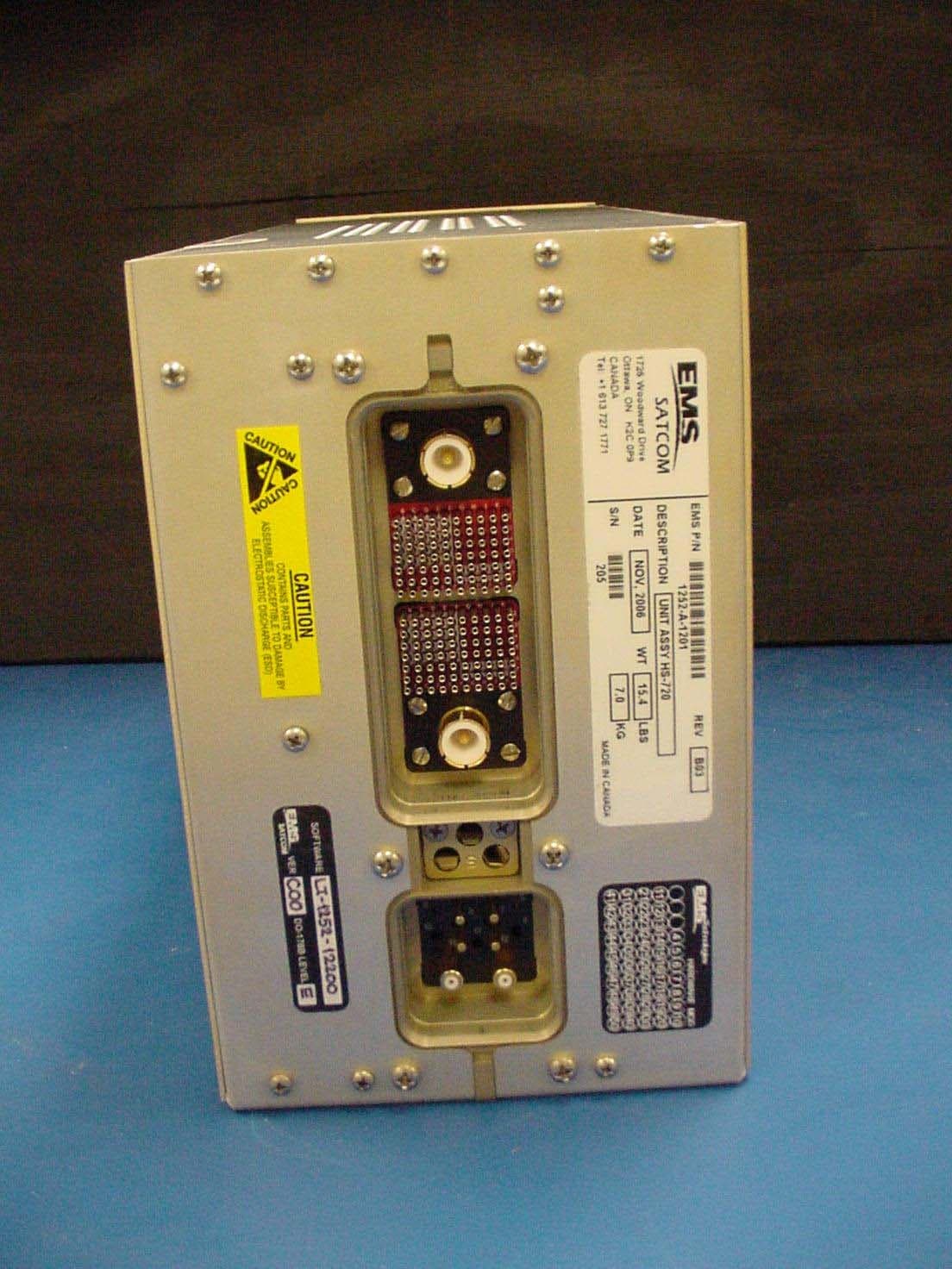
GB8HS-720
Sep 27, 2010High Speed Data Unit for the MCS-7200 SATCOM System
Equipment Class
TNB - Licensed Non-Broadcast Station Transmitter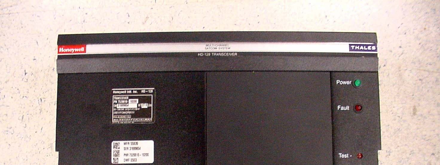
GB8HD-128
Feb 08, 2007SATCOM Transceiver
Equipment Class
TNB - Licensed Non-Broadcast Station Transmitter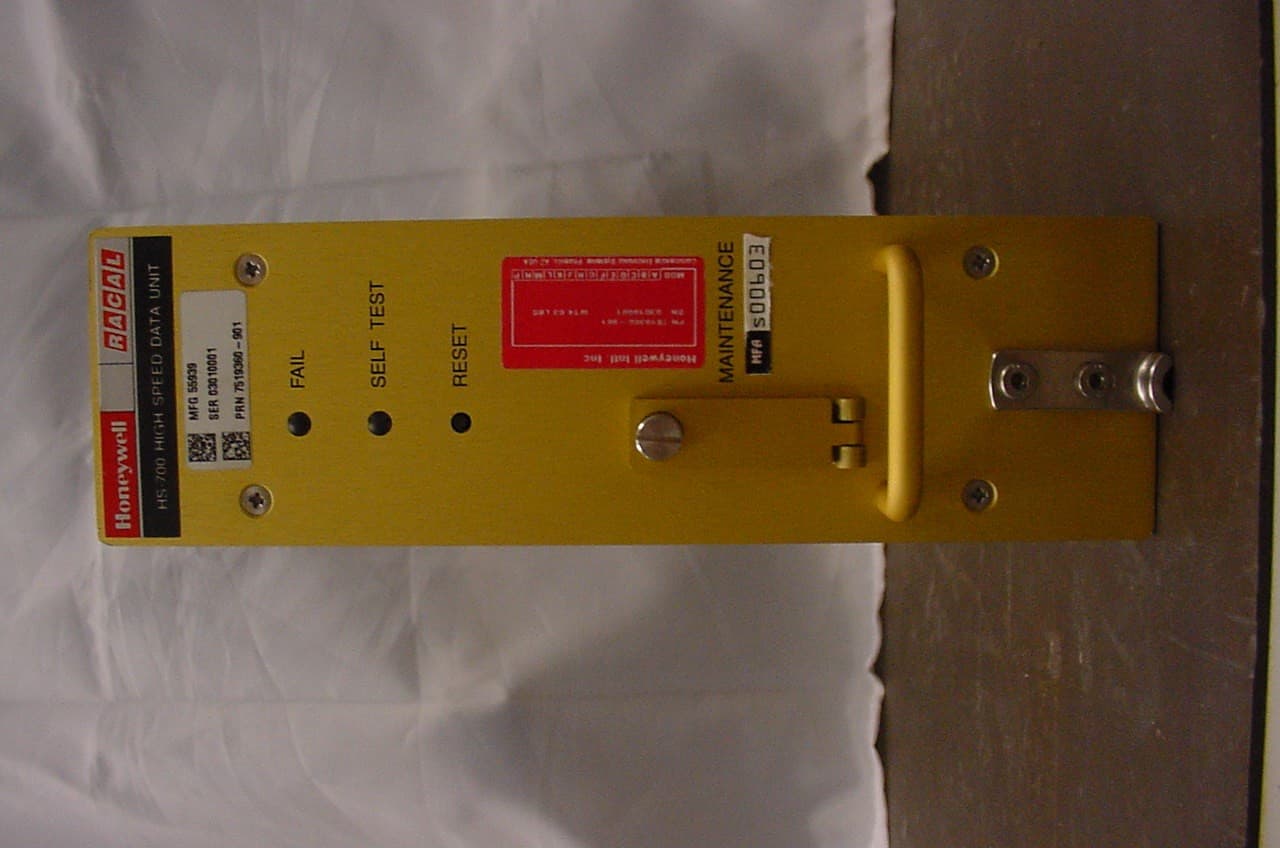
GB8HS-700
Jan 27, 2004Inmarsat Aircraft Telecommunications System
Equipment Class
TNB - Licensed Non-Broadcast Station Transmitter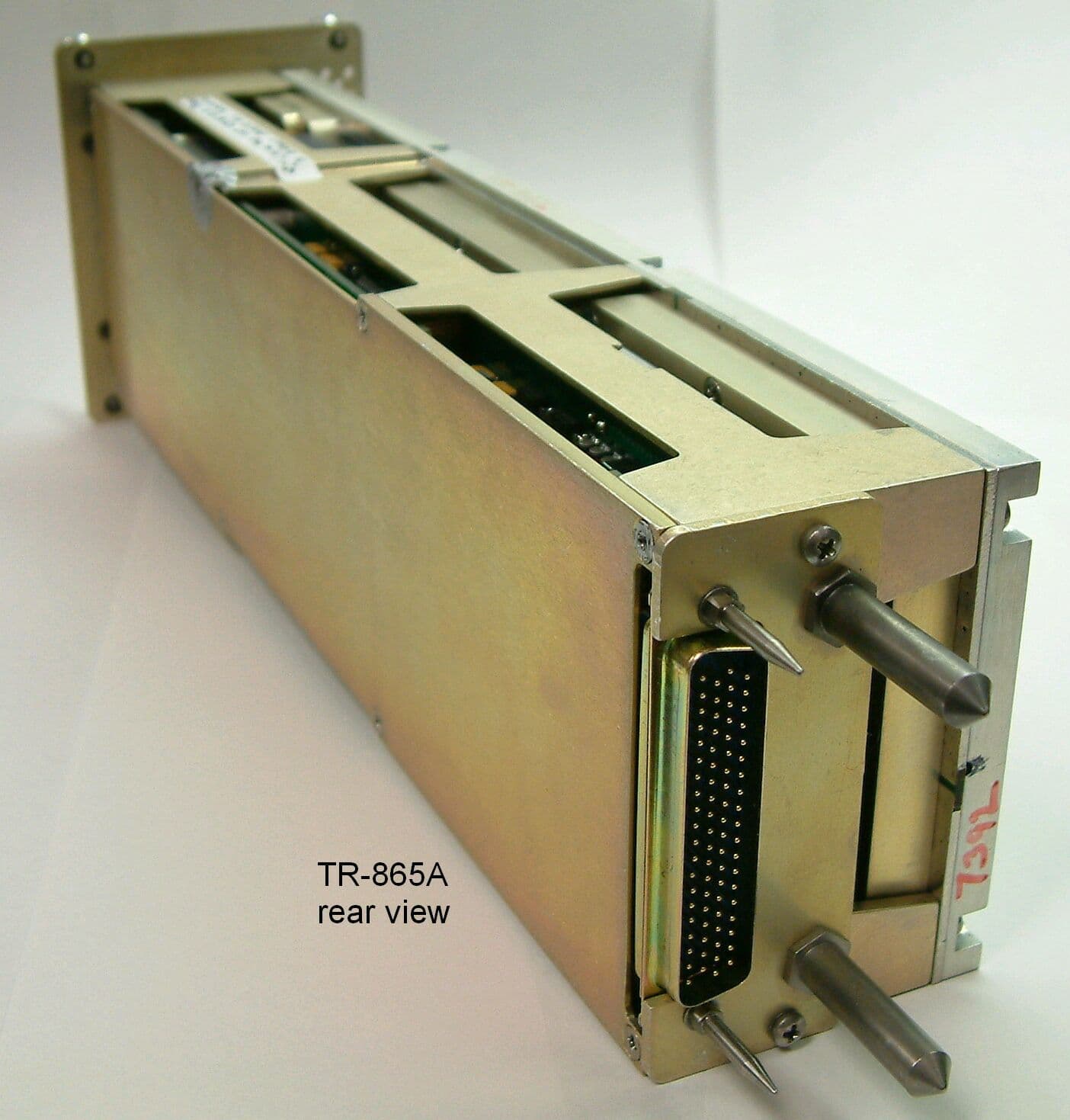
GB8TR865A
Apr 27, 2003Aviation VHF Transceiver
Equipment Class
TNB - Licensed Non-Broadcast Station Transmitter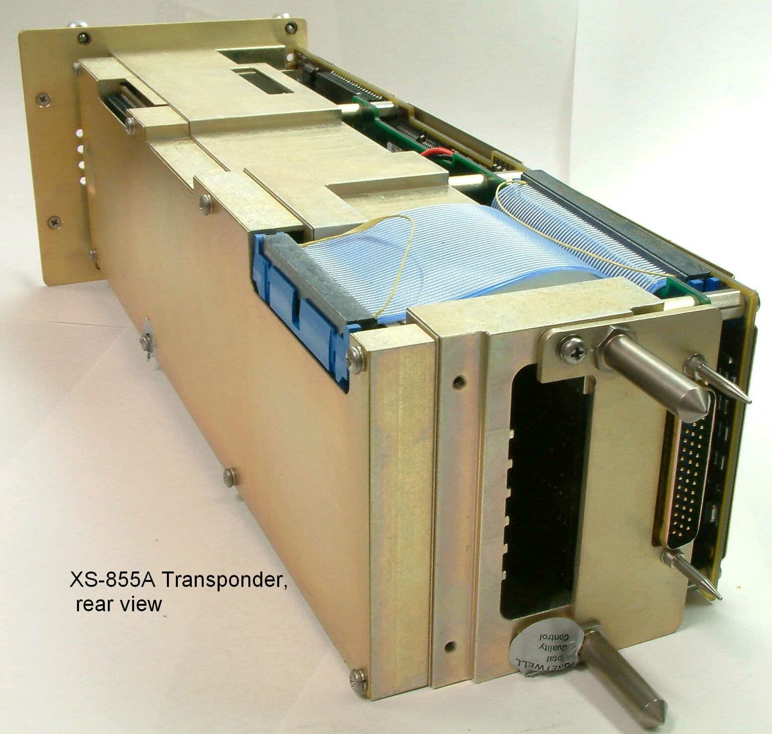
GB8XS855A
Mar 16, 2003UHF Pulsed L Band Transponder
Equipment Class
TNB - Licensed Non-Broadcast Station Transmitter