GB8XS855AUHF Pulsed L Band Transponder
Honeywell International Inc.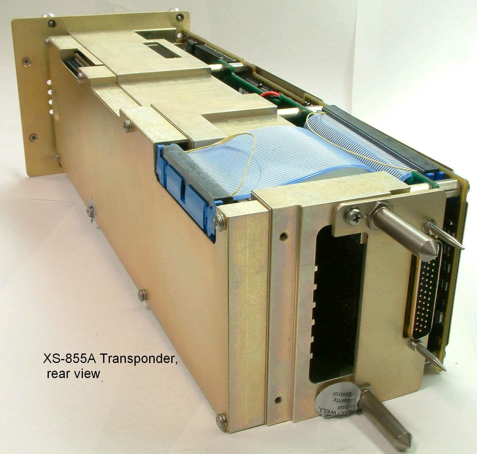
Click to zoom
Application Details
- Equipment Class
- TNB - Licensed Non-Broadcast Station Transmitter
- Date of Grant
- Mar 16, 2003
- Application Purpose
- Original Equipment
- Date of Application
- Dec 03, 2002
- Equipment Note
- UHF Pulsed L Band Transponder
- Frequency Range
- 1090.00000000 - 1090.00000000
- Company
- Honeywell International Inc.
- Country
- United States
Documents & Files
Document Text
Text extracted from the exhibit documents filed with the FCC. Open a document above to read the original.
Users Manual
OPERATING MANUAL 2B-09-00 Page 2 Nov 15/02 DIGITAL AUTOMATIC FLIGHT CONTROL SYSTEMS 1. MCDU Controls The radio tuning function is operated using a subset of the controls available on the MCDU, shown in Figure 31. DNEXT and PREV Function Keys-- NEXT and PREV function keys move to adjacent pages where more than one page of the same title is used DRADIOFunction Key-- The RADIO function key activates the radio tuning function and displays the RADIO 1/2 page, DTuning Knob-- The tuning knob is used to dial infrequencies orother numeric values. Figure 31 OPERATING MANUAL 2B-09-00 Page 3 Nov 15/02 DIGITAL AUTOMATIC FLIGHT CONTROL SYSTEMS 2. Page Organization The radio tuning function is accessed via the RADIO function key on the MCDU, which displays the RADIO 1/2 page. All other pages are accessed from RADIO 1/2 using the line select keys or the NEXT and PREV function keys, shown in Figure 32. Figure 32 Movement between the RADIO 1/2 and RADIO 2/2 pages is done with the NEXT and PREV function keys, while access to the COM DETAIL, TCAS/XPDR, and NAV DETAIL pages is via line select keys from RADIO 1/2 and access to the HF DETAIL, MLS DETAIL, and ADF DETAIL pages are via line select keys from RADIO 2/2. OPERATING MANUAL 2B-09-00 Page 4 Nov 15/02 DIGITAL AUTOMATIC FLIGHT CONTROL SYSTEMS 3. MCDU Tuning Description Allofthepages thatcorrespond toa particularradio type(e.g., VHFcommunications orADF) are arranged as shown in Figures 33,34, and35, andtypically consistof adetails pagealong with two memory pages. The details pages allow the specific features of each radio to be configured and provide access to the memory pages associated with each radio type. Figure 34 shows the pages associated with the VHF communications radios. Figure 33 OPERATING MANUAL 2B-09-00 Page 5 Nov 15/02 DIGITAL AUTOMATIC FLIGHT CONTROL SYSTEMS Figure 34 shows the pages associated with the VHF navigation radios. Figure 34 Figure 35 shows the pages associated with the TCAS/transponder subsystem Figure 35 OPERATING MANUAL 2B-09-00 Page 6 Nov 15/02 DIGITAL AUTOMATIC FLIGHT CONTROL SYSTEMS Figure 36 shows the arrangement of pages associated with the high--frequency (HF) communications radios. Figure 36 OPERATING MANUAL 2B-09-00 Page 7 Nov 15/02 DIGITAL AUTOMATIC FLIGHT CONTROL SYSTEMS Figure 37 shows the page associated with the automatic direction finder (ADF). Figure 37 OPERATING MANUAL 2B-09-00 Page 8 Nov 15/02 DIGITAL AUTOMATIC FLIGHT CONTROL SYSTEMS Figure 38 shows the pages associated with the Microwave Landing System (MLS) receiver. Figure 38 The RADIO MENU is used for manually tuning the radios. Pushing the RADIO key on the MCDU displays the RADIO MENU page 1/2. OPERATING MANUAL 2B-09-00 Page 9 Nov 15/02 DIGITAL AUTOMATIC FLIGHT CONTROL SYSTEMS 2B--09--20: BASIC OPERATION In keeping with the titling and numberingconventions usedby MCDU functions, eachMCDU page is arranged with a centered title at the top and a page number in the upper--right corner. Page numbers are formatted as the current page number (among those with the same page title), a slash î/î, and the number of pages with the same title. For example, there are two pages entitled îRADIO,î the first is labeled RADIO 1/2, as shown in Figure 39, and the second RADIO 2/2. The bottom line on each page displays the characters entered on the MCDU keypad and is called the scratchpad. The scratchpad is shared across all MCDU client functions,and is not under the control of the radio tuning function. The text area adjacent to each line select key (LSK) on the MCDU is referred to as a field, and identified by the LSK it is associated with. For example, the active frequency for VHF COM radio 1 (shown as COM1, 123.200) on the RADIO 1/2 page is in field 1L. Figure 39 OPERATING MANUAL 2B-09-00 Page 10 Nov 15/02 DIGITAL AUTOMATIC FLIGHT CONTROL SYSTEMS Pushing the NEXT or PREV key when this page is displayed displays the RADIO MENU page 2/2, shown in Figure 40. Figure 40 When the scratchpad is empty, pushing a line select key either moves the format cursor to the adjacent field, or performs the function indicated by the icon that appears near the key. The icons and their functions are described below. îSwapî frequencies. This symbol indicates that exchanges between the active and preset frequencies for the associated radio can be made. This has the effect of saving the currently active frequency in the preset memory, and tuning the radio to the frequency previously stored as the preset. Page indicator. When this icon is displayed, pushing the adjacent LSK changes the display to another page. The page to be displayed is eitherlabeled explicitly or itis adetail page for the radio in the associated field. OPERATING MANUAL 2B-09-00 Page 11 Nov 15/02 DIGITAL AUTOMATIC FLIGHT CONTROL SYSTEMS Exclusive selection. This icon is displayed next to a list of mutually exclusive options. Each time the adjacent LSK is pushed, the next options become selected, wrapping around to the first when the last option is reached. The selected value is displayed in the active color (greenin this document) and large font, while the other selection are displayed as smaller, whitecharacters. Immediate function. This icon indicates that the function identified in the field will be carried outimmediately whenthe adjacent LSK key is pushed. Copy value. This icon is used on the memory pages to indicate that the frequency highlighted by the format cursor will be copied into the active frequency for the associated radio. Format cursor. The cursor box highlights the value in the currently active field. Tuning curl. This icon indicates that the data value highlighted by the format cursor can be changed by turning the MCDU tuning knob. OPERATING MANUAL 2B-09-00 Page 12 Nov 15/02 DIGITAL AUTOMATIC FLIGHT CONTROL SYSTEMS IfLSK2R,thesecond onthe righthand side,shown inFigure 41,is pushed,the formatcursor and tuning curl move from the 2L field (COM1) to field 2R (COM2). Likewise, pushing LSK 3L moves the format cursor to…
Text truncated - open the document above for the full version.
Users Manual
OPERATING MANUAL 2B-09-00 Page 39 Nov 15/02 DIGITAL AUTOMATIC FLIGHT CONTROL SYSTEMS 1. ADF Memory As with the other radio types, the radio tuning function supports 12 ADF memories displayed on two pages. In addition to entering or dialing--in frequencies for each memory, a text label of up to 8 characters may be entered for each stored frequency. The default label for each memory is îMEMORYî, a dash, and the memory number, with the memory number always on the outboard edge of the display. The ADF Memory page is described below. Labels areenteredby typinginto thescratchpad andpushing theLSK adjacentto thedesired frequency. If the radio tuning function determines that the entry is a valid frequency for the radio, the entry is accepted into the frequency field. If not, the entry is considered a label and is entered into the label field above the frequency. A label canbe replacedby makinganother scratchpad entry into a memory field, or by pushing the DEL key. Pushing the DEL key places the text îDELETEî in the scratchpad and, when entered on a memory field, deletes the associated text label, returning itto thedefault. Ifthe DELkey is used ona memory where there is no user--entered label, the frequency is deleted from memory. Access to the ADF MEMORY 2/2 page is via the NEXT and PREV function keys. OPERATING MANUAL 2B-09-00 Page 40 Nov 15/02 DIGITAL AUTOMATIC FLIGHT CONTROL SYSTEMS This section displays and controls the Active ADF frequency on the selected radio (the field title will reflect which radio was selected). Pushing LSK 1L copies the field containing the format cursor into the active frequency and moves the previously active frequency into the preset field (not shown on this page). A scratchpad entry into the field replaces the preset frequency with the previous active frequency. These sections display the ADF memories 1--3 (7--9 on ADF MEMORY 2/2). These sections display the ADF memories 4--6 (10--12 on ADF MEMORY 2/2). Pushing this LSK displays ADF detail page. Pushing this LSK displays the RADIO 2/2 page. OPERATING MANUAL 2B-09-00 Page 41 Nov 15/02 DIGITAL AUTOMATIC FLIGHT CONTROL SYSTEMS 2B--09--70: MLS1 PAGE The MLS page, shown in Figure 43, shows the currently tuned procedure and a preset, azimuth and back--azimuth, and glidepath angle, and allows setting of the operating mode (automatic/manual) and azimuth selection (azimuth or back--azimuth). It also provides access to the MLS memory pages. Figure 43 Unlike the detail pages for the other radios, the MLS page does not support the fast memory tuning operation in field 3L. OPERATING MANUAL 2B-09-00 Page 42 Nov 15/02 DIGITAL AUTOMATIC FLIGHT CONTROL SYSTEMS 1. MLS Memory Pages The MLS memory pages,FINISH THIS SECTION Figure 44 OPERATING MANUAL 2B-09-00 Page 43 Nov 15/02 DIGITAL AUTOMATIC FLIGHT CONTROL SYSTEMS 2B--09--80: RADIOINTERACTIONS The MCDU radio tuning function communicates with the radio units using a bi--directional protocol. The radio tuning function expects to receive an acknowledgement when the radio is successful in completing each tuning command. A typical interaction begins with the user entering or dialing in a new frequency for a radio. The MCDU sends the appropriate tuning command to the specified radio and awaits confirmation. If no confirmation is received within the timeout period, the frequency display on the page is changed toamberand a scratchpad message is issued as shown in Figure 45). Figure 45 The pilot can attempt to tune the radio again, in the event that the fault was transient or has been cleared by crew action. This is also important in the event that the radio is receiving the command and is, in fact, tuning the radio, but is unable to respond to the MCDU. OPERATING MANUAL 2B-09-00 Page 44 Nov 15/02 DIGITAL AUTOMATIC FLIGHT CONTROL SYSTEMS 2B--09--90: ANNUNCIATIONMESSAGES 1. RADIO 1/2 Annunciations A variety of annunciations appear on the radio tuning pages, many of which are shown in Figure 46. Figure 46 OPERATING MANUAL 2B-09-00 Page 45 Nov 15/02 DIGITAL AUTOMATIC FLIGHT CONTROL SYSTEMS Table 33 describes the annunciators on RADIO 1/2. AnnunciatorDescription 25K Indicates that the associated VHF COM radio is set to 25KHz frequency spacing. When not present, the radio is tuning with 8.33KHz frequency spacing. DME H xxx This alert Indicates that the VHF navigation radio is tuning the corresponding DME receiver independently of the primary navigation frequency. IHBT This annunciator Indicates that tuning of the radio is inhibited, usually from a remote source (such as an emergency tuning function). MICSTK Indicates that the microphone button on the radio has been down long enough that the radio has identified it as îstuckî inthe transmit position. SQ This annunciator Indicates that the squelch feature for the radio is active. TX This annunciator Indicates that the radio is currently transmitting. RADIO 1/2 Annunciator Descriptions Table 33 OPERATING MANUAL 2B-09-00 Page 46 Nov 15/02 DIGITAL AUTOMATIC FLIGHT CONTROL SYSTEMS 2. RADIO 2/2 Annunciations A variety of annunciations appear on the radio tuning pages, many of which are shown in in Figure 46. Figure 47 OPERATING MANUAL 2B-09-00 Page 47 Nov 15/02 DIGITAL AUTOMATIC FLIGHT CONTROL SYSTEMS Table 34 describes the annunciators on RADIO 2/2. AnnunciatorDescription ANT The ADF radio is in antenna mode. ARM An MLS procedure is armed. BFO The ADF radio is operating in BFO mode. CW This annunciator Indicates that the radio is currently transmitting. IHBT Indicates that tuning of the radio is inhibited, usually from a remote source (such as an emergency tuning function). In the case of two HF radios sharing a single antenna, transmitting and/orreceivingmay beinhibitedperiodically whenthe otherHF radio has recently performed a transmit operation. ITU This annunciator Indicates that the radio is currently transmitting. LO The radio is set to low squelch. M An MLS parameter has been set manually. MED The radio is set to medium squelch. RX Indicates th…
Text truncated - open the document above for the full version.
Cover Letter(s)
FCC ID: GB8XS855A MFA p02a0004, d02b0022 Date of Report: Date of Submission: November 6, 2002 December 4, 2002 Federal Aviation Administration Spectrum Engineering Division ASR-1 800 Independence Ave. S.W. Washington, D.C. 20591 Attention: George Sakat Applicant: Honeywell International Inc. Commercial Electronic Systems - Phoenix FCC ID: GB8XS855A FCC Rules: 87 Gentlemen: As required under FCC Rule Part 87.147(d) please consider this letter, sent on behalf of the Applicant, as notification of the filing of an application Form 731 for the certification of the referenced equipment. Attached for your records, please find: 1. copy of the FCC Application Form 731 and full Test Data Report 2. copy of the proof of electronic filing to FCC with EA# 3. copy of the covering letter to the Commission 4. copy of the Agent Authorization letter for the writer to act on behalf of the Applicant. We trust the enclosed complies with your requirements. Should you need any further clarification, kindly contact the writer. Sincerely yours, Morton Flom, P. Eng. MF/cva enclosure(s) cc: Applicant cc: FCC via Electronic Filing cc: Industry Canada VIA CERTIFIED MAIL
Operational Description
Theory of Operation Transponder, XS-855A Emission type: 10M0P1D FCC Identifier: GB8XS855A The XS-855 mode A, C, and diversity Mode S transponder capable of responding to the ATC radio beacon (ATCRBS) Mode A and Mode C interrogations and to Mode S, (mode select) interrogations. Mode A would be the basic code directed by ATC to an aircraft for tracking and identification. Mode C would give ATC altitude information in 100 ft. increments for that aircraft while in flight. Mode S has also a feature called the “ICAO Address” which gives to the ATC controller a discrete address, common only to that aircraft and allows other features such as flight number to be imbedded into the Mode S coding. Mode S permits discrete addressing of individual aircraft and allows the transmission of messages back and forth between the aircraft and the ground station. Mode C information is acquired from an air-data unit elsewhere in the aircraft. Mode S is also a fundamental portion of the traffic alert and collision avoidance system (TCAS). The transponder uses a “L” band transmitter and has a transmitter power output of 500 watts peak pulse with a minimum of 250 watts and transmits on the frequency of 1090mhz and with a 60mhz intermediate frequency, receives on 1030mhz. The transponder is capable of operating from sea level to 70000 ft. The transmitter and receiver uses a VCO and phase locked loop to control frequency and to supply the mixer frequency for downconversion of the interrogation signal and for self-test of the RF circuitry. The transmitter power amplifier is a five-stage narrowband amplifier consisting of transistors Q1 through Q5. Besides providing amplification, Q1 through Q3 also act as RF switches. Q1 is turned on for the duration of the reply envelope. Q2 operates class C and is turned on for the duration of the reply envelope by the RF signal from Q1. Q3 is turned on for the duration of each reply pulse by the modulator. The envelope and pulse modulation signals shape the CW carrier into the reply pulse train. Q4 and Q5 provide high power amplification. The five amplifier stages raise the power level by several orders of magnitude, from 25mw at the base of Q1 to 500 watt pulsed RF at the output of Q5. Maximum power gain is approximately 43db.
Parts List/Tune Up Info
ENGINEERING SPECIFICATION SECURITY NOTATION SPEC NO. IT7517400 CAGE CODE 55939 AG REV LTR THIS TITLE PAGE CONTAINS PROPRIETARY AND DATA RIGHTS NOTATIONS. "DOCUMENT TYPE INTEGRATED TEST SPECIFICATION DIVISION I DEPARTMENT NO. PRODUCT LINE NO. BCAS I 5810 3834 CLASS I INITIAL RELEASE DATE A I 3 SEP 92 CONTRACTNO. TITLE INTEGRATED TEST SPECIFICATION FOR THE XS-852, XS-852A, XS-852B, XS-852C, XS-852D, XS-855A, XS-855B, XS-855C,'XS-856A, XS-856B, XS-856C, XS-857 DIVERSITY TRANSPONDERS PIN 7517400-9XX, 8XX, EXCEPT-905 PREPARED BY: DATE J. Troxel 9-3-92 APPROVED FORSCM DATE REF AWAEBIPSAEB NO. I CHECKER APPROVED BY TECHNICAL DATE MANAGER APPROVED FOR SQA DATE PRODUCT DESIGN CHECKER (FOR REF, SPCL CONTPER EPMI-A..40) APPROVED BY ENGINEERING DEPARTMENT MANAGER B. Fuller DATE 9-3-92 APPROVED BY: DATE COGNIZANCE OF QE SUPVR (FOR REF, SPCL CONT PER EPM 1-A-40) FOR PAGE INDEX, SEE PAGE CR-2. REVISION RECORD FOLLOWS PAGE INDEX. THIS IS AN ELECTRONIC FACSIMILE OF THE CR-1 ON FILE WITH DOCUMENT CONTROL. PROPRIETARY NOTICE THIS DOCUMENT AND THE INFORMATION DISCLOSED HEREIN ARE PROPRIETARY DATA OF HONEYWELL INC. NEITHER THIS DOCUMENT NOR THE INFORMATION CONTAINED HEREIN SHALL BE REPRODUCED, USED, OR DISCLOSED TO OTHERS WITHOUT THE WRITTEN AUTHORIZATION OF HONEYWELL INC. NOTICE FREEDOM OF INFORMATION ACT (5 USC 552) AND DISCLOSURE OF CONFIDENCE INFORMATION GENERALLY (18 USC 1905) THIS DOCUMENT IS BEING FURNISHED IN CONFIDENCE BY HONEYWELL INC. THE INFORMATION DISCLOSED HEREIN FALLS WITHIN EXEMPTION (b) (4) OF 5 USC 552 AND THE PROHIBITIONS OF 18 USC 1905. Copyright 1999 Honeywell Inc. All Rights Reserved Honeywell 15101-000 (REV 970213 BCAS ASF5900/ENG_SPEC.DOT) AWICRITICAL NOTATION SECURITY NOTATION NEW lll199-OFC97-LOGISTICSIBCAS) HONEYWELL INC. TITLE PAGE CR-1 PAGE ENGINEERING SPECIFICATION SECURITY NOTATION SPEC NO. IT7517400 CAGE CODE 55939 AG REV LTR SEE THE TITLE PAGE FOR PROPRIETARY AND DATA RIGHTS NOTATIONS. THE LATEST REVISION OF EACH SHEET IS INDICATED ON THE PAGE INDEX. Rev Page Ltr Rev Rev Rev Rev Page Ltr Page Ltr Page Ltr Page Ltr Title 33 P 78 P CR-1 AG 34 AF 79 AF 35 AF 80 P Page Index 36 P 81 P CR-2 AG 37 P 82 P Revision 38 P 83 P Record 39 T 84 P CR-3 AG 40 T 85 T 41 AF 86 AF Table of 42 R 87 T Contents 43 P 88 T i AB 44 R 89 P ii P 45 P 90 P 1 AF 46 P 91 P 2 AE 47 AF 92 P 3 AF 48 R 93 P 4 p 49 P 94 P 5 AF 50 P 95 T 6 AF 51 P 96 P 7 AB 52 P 97 AE 8 p 53 P 98 AE 9 AF 54 P 99 P 10 AF 55 AA 100 AB 11 AF 56 AA 101 P 12 U 57 R 102 AE 13 AF 58 P 103 AE 14 p 59 AF 104 AE 15 AF 60 AF 105 T 16 AF 61 AF 106 T 17 AB 62 P 107 AE 18 p 63 P 108 T 19 p 64 R 109 P 20 p 65 AF 110 AE 21 p 66 AF 111 AE 22 y 67 AE 112 AE 23 AF 68 P 113 P 24 y 69 AB 114 AE 25 y 70 P 115 AE 26 AF 71 P 116 AE 27 p 72 P 117 P 28 p 73 AB 118 AE 29 p 74 V 119 AE 30 R 75 AG 120 P 31 p 76 AF 121 AF 32 AF 77 P Appendix A A-0 P A-1 P A-2 P A-3 P Appendix B B-0 P B-1 AF B-2 AF B-3 AF B-4 AF B-5 V B-6 V Appendix C C-0 P C-1 AD C-2 C-3 C-4 C-5 C-6 C-7 C-8 C-9 C-10 C-11 C-12 P Appendix D D-0 P D-1 P D-2 P D-3 P D-4 P D-5 P D-6 P D-7 P Appendix E E-0 P E-1 P E-2 P E-3 P E-4 P E-5 P E-6 P E-7 P E-8 P E-9 P E-10 P E-11 P E-12 P E-13 P E-14 E-15 E-16 E-17 E-18 E-19 E-20 E-21 E-22 E-23 :~ E-24 E-25 E-26 E-27 E-28 E-29 TOTAL PAGES: 188 Honeywell 15102-000 (REV 970213 BCAS ASF5900/ENG_SPEC.DOT) AWlCRITICAL NOTATION SECURITY NOTATION NEW llI/99-OFC97-LOGISTICS/BCAS) HONEYWELL INC. PAGE INDEX CR-2 PAGE ENGINEERING SPECIFICATION SECURITY NOTATION SPEC NO. IT7517400 CAGE CODE 55939 AG REV LTR SEE THE TITLE PAGE FOR PROPRIETARY AND DATA RIGHTS NOTATIONS. REV PAGE DESCRIPTION DATE AND APPROVAL LTR P SEE PAGE INDEX SHEET CR-2 R SEE PAGE INDEX SHEET CR-2 T SEE PAGE INDEX SHEET CR-2 U SEE PAGE INDEX SHEET CR-2 V SEE PAGE INDEX SHEET CR-2 W SEE PAGE INDEX SHEET CR-2 Y SEE PAGE INDEX SHEET CR-2 AA SEE PAGE INDEX SHEET CR-2 AB SEE PAGE INDEX SHEET CR-2 AC SEE PAGE INDEX SHEET CR-2 AD SEE PAGE INDEX SHEET CR-2 AE AF SHEET CR-2 SEE REV N FOR PREVIOUS REVISION INFORMATION. DOC. CONVERTED TO LATEST FORMAT C.O. 101099 (MAKE) C.O. 106557 (MAKE) C.O. 26301 (NA) C.O. 28463 (BREAK IN*) C.O. 101141 (BREAK IN*) C.O. 26780 (NA) C.O. 24592 (NA) C.O. 26205(NA) C.O. 25560 (NA) C.O. 200200014A (NA) C.O. 200200408A (NA) SEE PAGEINDEX C.O. 200200987A (NA) SHEET CR-2 SEE PAGE INDEX C.O. 200203305A (MAKE) AG SEE PAGE INDEX SHEET CR-2 C.O. 200203473A (NA) Tom Sisco 25 Aug 99 Tom Sisco 4 Nov 99 Tom Sisco 2 Mar 00 M. Inouye 9 May 00 T. Sisco 9 Jan 01 J. Ellis 9 Jan 01 T. Sisco 23 Apr 01 M. Ports 30 Jul 01 M. Ports 30 Jul 01 T. Sisco 25 Mar 02 M. Ports 2 April 02 M. Ports 7 Jun 02 M. Ports 13 Sep 02 S. Genack K. Stauffer Hone vell AWICRITICAL NOTATION SECURITY NOTATION REVISION RECORDS CR-3 PAGE 5200-018 (REV 970213 BCAS ASF5900/ENG_SPEC.DOT) ) ( NEW 111199-OFC97-LOGISTICSIBCAS) HONEYWELL INC SECURITY NOTATIONSPEC NO. IT7517400 SEE PAGE INDEX FOR THIS SHEET REV LETTER CAGE CODE 55939 REV LTR SEE THE TITLE PAGE FOR PROPRIETARY AND DATA RIGHTS NOTATIONS. REV LTR AW/CRITICAL NOTATION TABLE OF CONTENTS i SECURITY NOTATIONPAGE 5200-032 (REV 970213 BCAS ASF5900/ENG_SPEC.DOT) ) ( NEW 1/1/99-OFC97-LOGISTICS/BCAS) HONEYWELL INC. ENGINEERING SPECIFICATION Table of Contents TitlePage 1.SCOPE ...................................................................................................................1 2.REFERENCE DOCUMENTS....................................................................................1 3.GENERAL INFORMATION ......................................................................................2 4.POWER AND SIGNAL REQUIREMENTS ................................................................4 4.1POWER REQUIRED.......................................................................................................4 4.2S IGNALS.....................................................................................................................4 5.TEST EQUIPMENT..................................................................................................5 5.1HONEYWELL T…
Text truncated - open the document above for the full version.
Parts List/Tune Up Info
J.ELLER B 55939 7517460-855 7517400 01-03-19 CIRCUIT CARD ASSEMBLY- 1 9 STATIC SENS 7517400 TRANSMITTER,A5 1 1 EA 7517461-5 7517461-5 PWB TRANSMITTER 2 1 EA 7517489-1 7517489-1 H0USING TRANSMITTER HOG OUT 3 1 EA 7517495 7517495 SHIELD HOG OUT 4 1 EA 7517497-901 7517497-901 SHIELD 3 5 16 EA 7516275-408 7516275-408 SCREW PNH CRES 40-40X1-4 8 4 EA 07187 0920-18 MS51959-18 SCREW CSKH CRES 4-40X5-8 MIL-S-7742 9 6 EA 07187 0919-3 MS51957-3 SCREW PNH CRES 2-56X1-4 MIL-S-7742 10 6 EA 07187 0770-3 MS15795-802 WASHER CRES 0.094 ID 11 6 EA 07187 0164-3 0164-3 WASHER CRES 0.097 ID V 51 3 EA 7002013-406 7002013-406 CAP 0.6 T0 4.5 PF 500 VDCW V C 39 02 C 42 02 C 49 02 52 15 EA 7011730-437 7011730-437 CAP 0.10 UF !10% 50 VDCW V SURFACE MOUNT C 2 02 C 14 01 C 15 01 C 18 01 C 20 01 C 25 01 C 29 01 C 33 01 C 35 01 C 36 01 C 37 01 C 71 03 C 74 03 C 78 03 C 81 03 53 1 EA 7011730-524 7011730-524 CAP 8200 PF !10% 100 VDCW V SURFACE MOUNT C 8 02 54 2 EA 7011730-525 7011730-525 CAP 0.010 UF !10% 100 VDCW V SURFACE MOUNT C 61 03 C 63 03 55 2 EA 7011730-540 7011730-540 CAP 0.10 UF !10% 100 VDCW V SURFACE MOUNT C 40 02 C 47 02 56 2 EA 7013064-713 7013064-713 CAP 10 UF !10% 35 VDCW V SURFACE MOUNT C 32 01 C 38 01 57 3 EA 7019549-401 7019549-401 CAP 3 UF !10% 100 VDCW V C 43 02 C 44 02 C 45 02 58 3 EA 7022905-13 7022905-13 CAP 1.3 PF !0.1 PF 150 VDCW V C 11 01 C 21 01 C 22 01 59 4 EA 7022905-144 7022905-144 CAP 7.5 PF !5% 500 VDCW V C 52 03 C 55 03 C 56 03 C 59 03 ASSEMBLY VARIABLES CONTINUED ON FOLLOWING PAGE J.ELLER B 55939 7517460-855 7517400 01-03-19 CIRCUIT CARD ASSEMBLY- 2 9 STATIC SENS 7517400 TRANSMITTER,A5 60 4 EA 7022905-146 7022905-146 CAP 9.1 PF !5% 500 VDCW V C 64 03 C 65 03 C 77 03 C 84 03 61 37 EA 7022905-157 7022905-157 CAP 27 PF !5% 500 VDCW V C 1 02 C 3 02 C 4 02 C 5 02 C 6 02 C 7 02 C 9 02 C 10 01 C 16 01 C 17 01 C 19 01 C 23 01 C 24 01 C 26 01 C 41 02 C 46 03 C 48 02 C 50 02 C 51 02 C 53 03 C 54 03 C 57 03 C 58 03 C 60 03 C 62 03 C 66 03 C 68 03 C 69 03 C 70 03 C 72 03 C 73 03 C 75 03 C 76 03 C 79 03 C 80 03 C 82 03 C 83 03 62 1 EA 7022905-28 7022905-28 CAP 3.9 PF !0.1 PF 150 VDCW V C 12 01 63 2 EA 7022905-33 7022905-33 CAP 6.2 PF !0.25 PF 150 VDCW V C 85 03 C 86 03 64 7 EA 7500054-102 7500054-102 CAP 1000 PF !5% 50 VDCW V SURFACE MOUNT C 13 01 C 27 01 C 28 01 C 30 01 C 31 01 C 34 01 C 67 03 65 4 EA 7018373-125 7018373-125 DI0DE SURFACE MOUNT V CR 7 03 CR 8 03 CR 11 03 CR 12 03 66 4 EA 7018422-160 7018422-160 DI0DE STATIC SENSITIVE DEVICE V SURFACE MOUNT CR 5 03 CR 6 03 CR 9 03 CR 10 03 67 2 EA 7500075-101 7500075-101 DI0DE STATIC SENSITIVE DEVICE V SURFACE MOUNT CR 1 02 CR 4 01 68 4 EA 7500077-18 7500077-18 DI0DE STATIC SENSITIVE DEVICE V SURFACE MOUNT CR 3 01 CR 13 03 CR 14 03 ASSEMBLY VARIABLES CONTINUED ON FOLLOWING PAGE J.ELLER B 55939 7517460-855 7517400 01-03-19 CIRCUIT CARD ASSEMBLY- 3 9 STATIC SENS 7517400 TRANSMITTER,A5 CR 17 03 69 1 EA 7500103-31 7500103-31 DI0DE STATIC SENSITIVE DEVICE V BBY31 SURFACE MOUNT CR 2 01 70 1 EA 7500361-100 7500361-100 DI0DE STATIC SENSITIVE DEVICE V SURFACE MOUNT CR 18 03 71 2 EA 7500595-200 7500595-200 DI0DE STATIC SENSITIVE DEVICE V CR 15 03 CR 16 03 72 2 EA 7018376-1 7018376-1 FILTER FL 1 03 FL 2 03 V 73 1 EA 7019335-204 7019335-204 C0NN J 1 04 V 74 1 EA 7018334-2 7018334-2 INDUCT0R 125 UH SMD V SURFACE MOUNT L 7 01 75 1 EA 7018971-103 7018971-103 C0IL 10.0 UH !10% V SURFACE MOUNT L 6 01 76 9 EA 7018971-680 7018971-680 C0IL 0.068 UH !10% V SMD L 1 01 L 2 01 L 3 01 L 4 01 L 5 01 L 8 03 L 9 03 L 10 03 L 11 03 77 1 EA 7019335-320 7019335-320 C0NN P 3 04 V 78 1 EA 7017937-486 7017937-486 XSTR STATIC SENSITIVE DEVICE V Q 6 01 79 1 EA 7018401-58 7018401-58 XSTR STATIC SENSITIVE DEVICE V SD8280-01 Q 3 02 80 1 EA 7018402-875 7018402-875 XSTR STATIC SENSITIVE DEVICE V SD8281-01 Q 4 02 81 1 EA 7018768-502 7018768-502 XSTR STATIC SENSITIVE DEVICE V Q 5 02 82 1 EA 7500382-1 7500382-1 XSTR RF,P0WER V 1000 STATIC SENSITIVE DEVICE Q 1 02 83 1 EA 7500382-4 7500382-4 XSTR STATIC SENSITIVE DEVICE V ASSEMBLY VARIABLES CONTINUED ON FOLLOWING PAGE J.ELLER B 55939 7517460-855 7517400 01-03-19 CIRCUIT CARD ASSEMBLY- 4 9 STATIC SENS 7517400 TRANSMITTER,A5 Q 2 02 84 2 EA 7018400-338 7018400-338 RESIST0R 274 OHMS !1% 1 W V SURFACE MOUNT R 66 03 R 69 03 85 2 EA 7018400-368 7018400-368 RESIST0R 562 OHMS !1% 1 W V SURFACE MOUNT R 65 03 R 68 03 86 8 EA 7500042-200 7500042-200 RESIST0R 10.0 0HMS !1% 1/4 W V SURFACE MOUNT R 3 02 R 8 02 R 9 02 R 24 01 R 40 02 R 41 02 R 42 02 R 43 02 87 15 EA 7500042-268 7500042-268 RESIST0R 51.1 0HMS !1% 1/4 W V SURFACE MOUNT R 11 01 R 20 01 R 22 01 R 50 03 R 52 03 R 54 03 R 55 03 R 58 03 R 59 03 R 60 03 R 61 03 R 62 03 R 67 03 R 71 03 R 74 03 88 1 EA 7500042-284 7500042-284 RESIST0R 75.0 0HMS !1% 1/4 W V SURFACE MOUNT R 4 02 89 7 EA 7500042-296 7500042-296 RESIST0R 100 0HMS !1% 1/4 W V SURFACE MOUNT R 13 01 R 34 01 R 44 03 R 45 03 R 46 03 R 47 03 R 76 03 90 11 EA 7500042-313 7500042-313 RESIST0R 150 0HMS !1% 1/4 W V SURFACE MOUNT R 6 02 R 10 01 R 12 01 R 49 03 R 51 03 R 53 03 R 56 03 R 70 03 R 72 03 R 73 03 R 75 03 91 1 EA 7500042-333 7500042-333 RESIST0R 243 0HMS !1% 1/4 W V SURFACE MOUNT R 19 01 92 5 EA 7500042-364 7500042-364 RESIST0R 511 0HMS !1% 1/4 W V SURFACE MOUNT R 23 01 R 25 01 R 27 01 ASSEMBLY VARIABLES CONTINUED ON FOLLOWING PAGE J.ELLER B 55939 7517460-855 7517400 01-03-19 CIRCUIT CARD ASSEMBLY- 5 9 STATIC SENS 7517400 TRANSMITTER,A5 R 36 01 R 64 03 93 1 EA 7500042-380 7500042-380 RESIST0R 750 0HMS !1% 1/4 W V SURFACE MOUNT R 7 02 94 3 EA 7500042-392 7500042-392 RESIST0R 1000 0HMS !1% 1/4 W V SURFACE MOUNT R 5 02 R 31 01 R 33 01 95 2 EA 7500042-409 7500042-409 RESIST0R 1500 0HMS !1% 1/4 W V SURFACE MOUNT R 16 01 R 17 01 96 1 EA 7500042-414 7500042-414 RESIST0R 1690 0HMS !1% 1/4 W V SURFACE MOUNT R 18 01 97 2 EA 7500042-429 7500042-429 RESIST0R 2430 0HMS !1% 1/4 W V SURFACE MOUNT R 26 01 R 29 01 98 7 EA 7500042-488 7500042-488 RESIST0R 10,000 0HMS !1% 1/4 W V SURFACE MOUNT R 14 01 R 21 01 R 37 01 R 38 01 R 39 01 R 63 03 R200 01 99 3 EA 750…
Text truncated - open the document above for the full version.
RF Exposure Info
FCC ID: GB8XS855A MFA p02a0004, d02b0024 Date of Report: Date of Submission: November 6, 2002 December 4, 2002 Federal Communications Commission Via: Electronic Filing Attention: Authorization & Evaluation Division Applicant: Honeywell Inc, Commercial Flight Systems Group Equipment: XS-855A FCC ID: GB8XS855A FCC Rules: Radiofrequency Radiation Exposure Limits 47 CFR 1.1310 MPE - Mobiles x Fixed Based Station Gentlemen: On behalf of the Applicant, enclosed please find the Calculated Report, the whole for Environmental Assessment (MPE) of the referenced equipment as shown. We trust the same is in order. Should you need any further information, kindly contact the writer who is authorized to act as agent. Sincerely yours, Morton Flom, P. Eng. enclosure(s) cc: Applicant MF/cva FCC ID: GB8XS855A MFA p02a0004, d02b0024 ENVIRONMENTAL ASSESSMENT for MOBILES/FIXED BASE STATION for FCC ID: FCC ID: GB8XS855A Model:XS-855A to FEDERAL COMMUNICATIONS COMMISSION 47 CFR 1.1310 (MPE) Radiofrequency Radiation Exposure Limits DATE OF REPORT: November 6, 2002 ON THE BEHALF OF THE APPLICANT: Honeywell International Inc. Commercial Electronic Systems - Phoenix AT THE REQUEST OF: P.O. Part of X305730L-06B Mailing: Honeywell Inc. Business, Regional & General Aviation 5353 W. Bell Road, MS 2DD80 Glendale, AZ 85308 Attention of: Robert H. Fuller, Technical Mgr, EPIC Eng'g 602 436 4714; FAX: -4040 M/S 2DD80 [email protected] SUPERVISED BY: Morton Flom, P. Eng. FCC ID: GB8XS855A MFA p02a0004, d02b0024 TABLE OF CONTENTS RULEDESCRIPTIONPAGE . Test Report 1 . Identification of the Equipment Under Test 2 . Standard Test Conditions and Engineering Practices 4 1.1310 Environmental Assessment 5 FCC ID: GB8XS855A MFA p02a0004, d02b0024 PAGE NO.1of5. Required information per ISO/IEC Guide 25-1990, paragraph 13.2: a) TEST REPORT (SUPPLEMENTAL) b) Laboratory: (FCC: 31040/SIT) (Canada: IC 2044) M. Flom Associates, Inc. 3356 N. San Marcos Place, Suite 107 Chandler, AZ 85225 c) Report Number: d02b0024 d) Client: Honeywell Inc, Commercial Flight Systems Group Business and Commuter Aviation Systems PO Box 29000 Phoenix, AZ 85038-9000 e) Identification: XS-855A FCC ID: GB8XS855A Description: UHF Pulsed L Band Transponder f) EUT Condition: Not required unless specified in individual tests. g) Report Date: November 6, 2002 EUT Received: October 23, 2002 h, j, k): As indicated in individual tests. i) Sampling method: No sampling procedure used. l) Uncertainty: In accordance with MFA internal quality manual. m) Supervised by: Morton Flom, P. Eng. n) Results: The re…
Text truncated - open the document above for the full version.
Contact Information
Applicant
Mike Matthews(Certification Engineer)
Technical Contact
M. Flom Associates, IncMorton Flom
[email protected]480 926 3100
3356 N. San Marcos Pl., Suite 107 · Chandler, Arizona · United States
Non-Technical Contact
M. Flom Associates, Inc.Morton Flom
[email protected]480 926 3100
Test Firm
M. Flom Associates, Inc.Morton Flom
Technical Specifications
| # | Rule Parts | Frequency Range | Power Output | Emission | Tolerance |
|---|---|---|---|---|---|
| 1 | 87 | 1.09 GHz - 1.09 GHz | 500 W | 11M9P0N | 0.1000000000 % |
Other Applications from Honeywell International Inc.
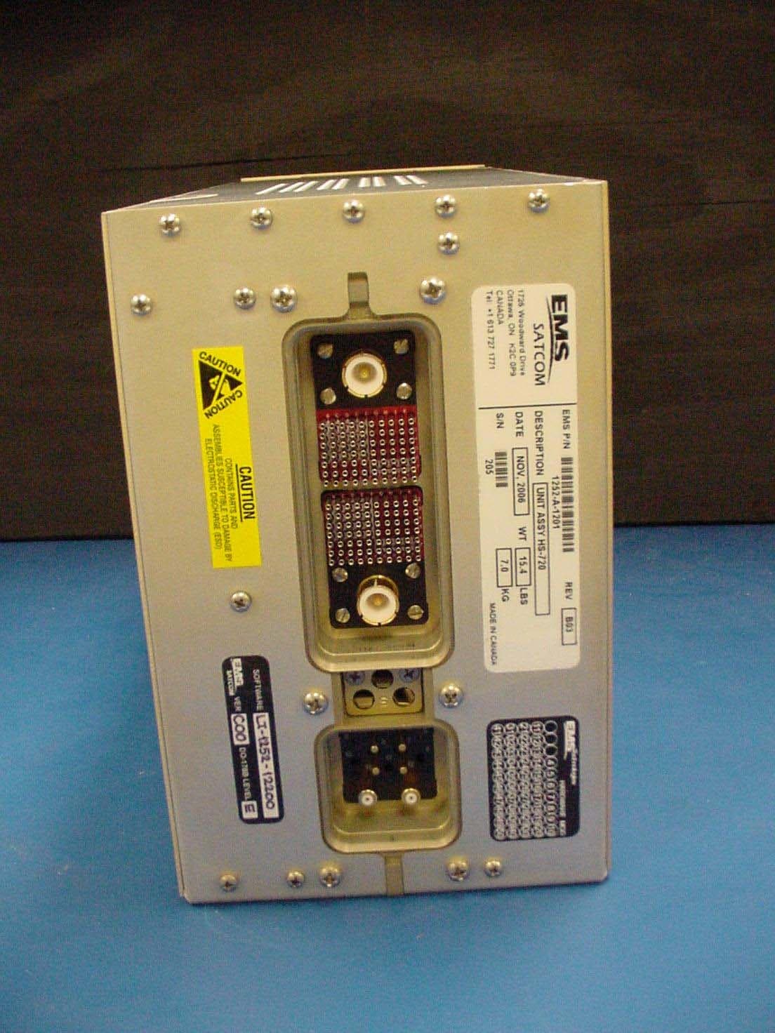
GB8HS-720
Sep 27, 2010High Speed Data Unit for the MCS-7200 SATCOM System
Equipment Class
TNB - Licensed Non-Broadcast Station Transmitter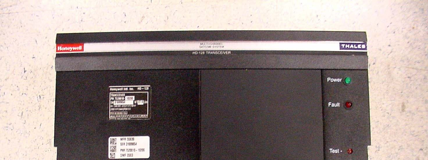
GB8HD-128
Feb 08, 2007SATCOM Transceiver
Equipment Class
TNB - Licensed Non-Broadcast Station Transmitter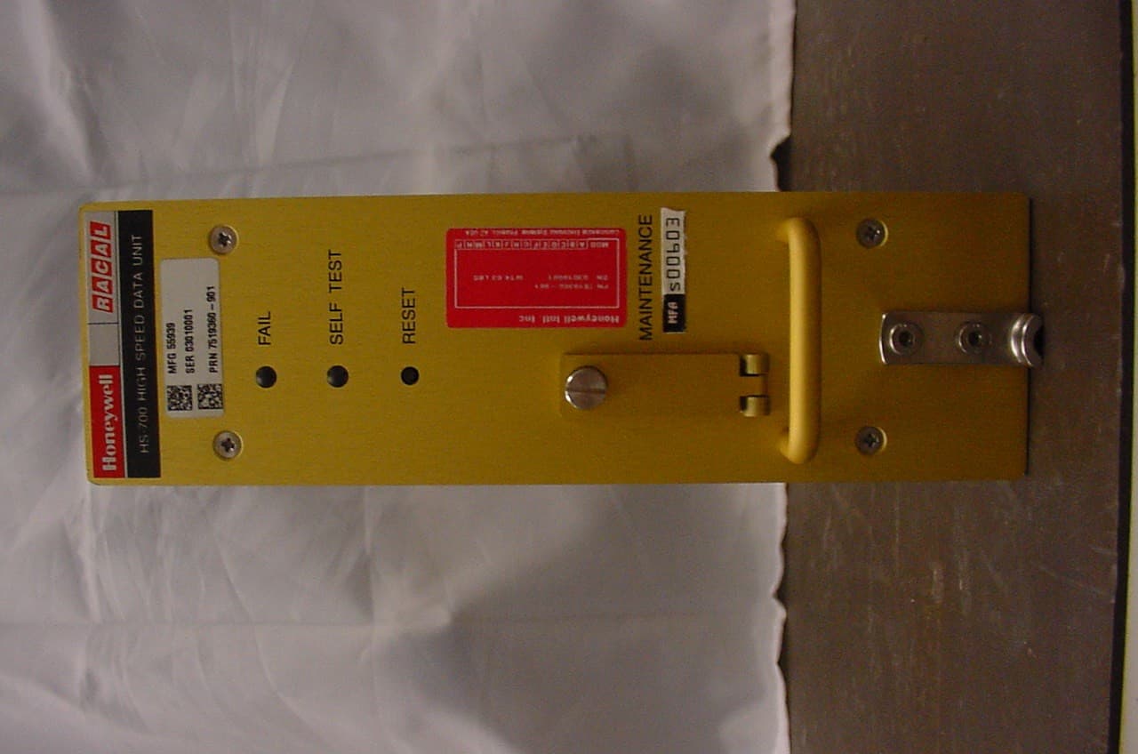
GB8HS-700
Jan 27, 2004Inmarsat Aircraft Telecommunications System
Equipment Class
TNB - Licensed Non-Broadcast Station Transmitter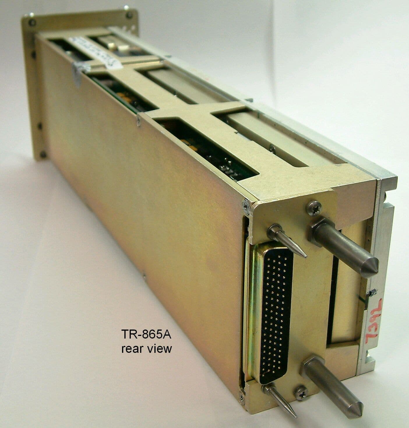
GB8TR865A
Apr 27, 2003Aviation VHF Transceiver
Equipment Class
TNB - Licensed Non-Broadcast Station Transmitter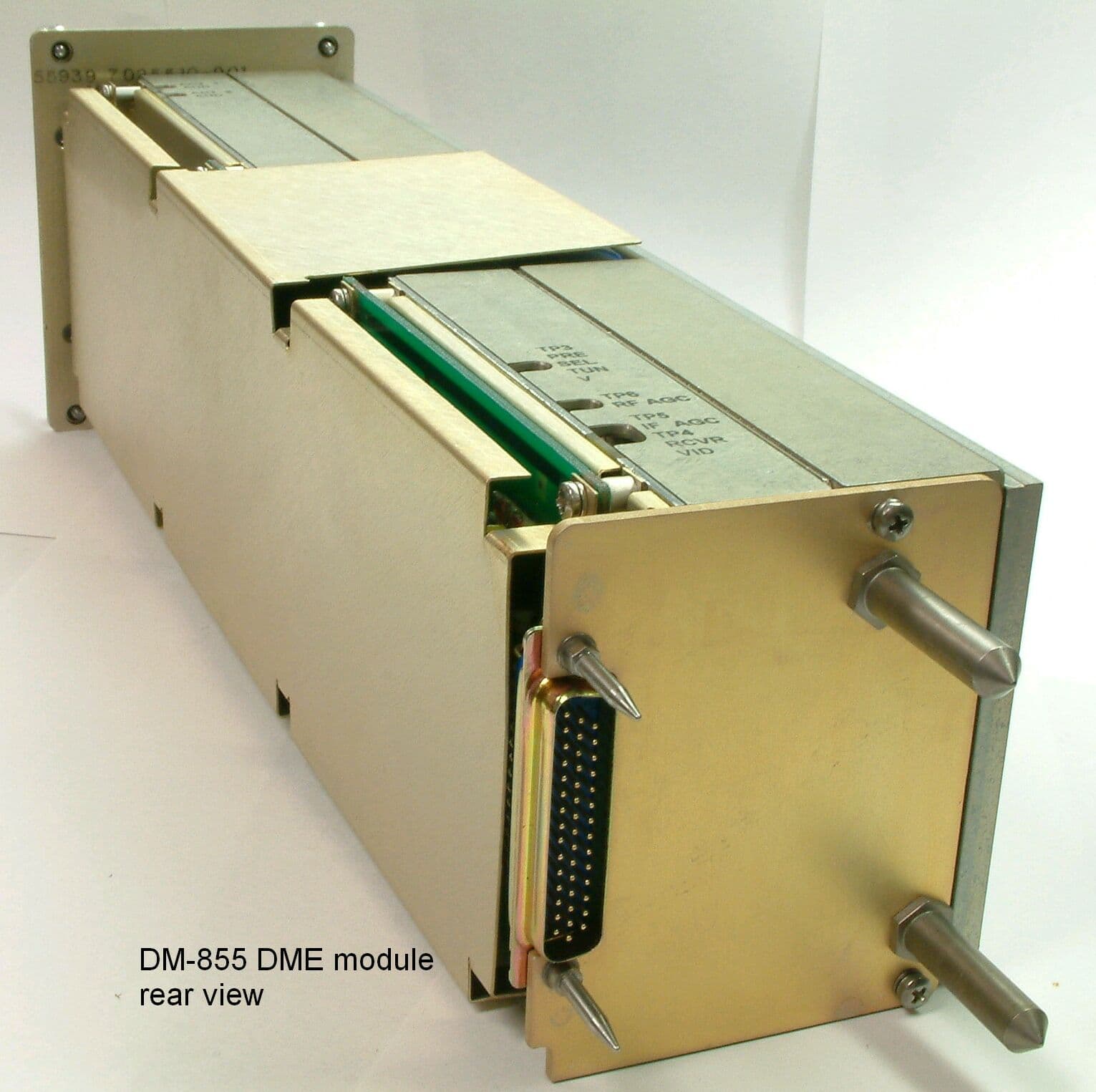
GB8DM855
Mar 12, 2003UHF Pulsed L Band TRX
Equipment Class
TNB - Licensed Non-Broadcast Station Transmitter