GB8TR865AAviation VHF Transceiver
Honeywell International Inc.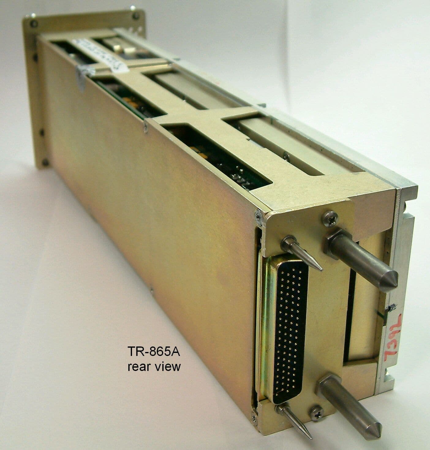
Click to zoom
Application Details
- Equipment Class
- TNB - Licensed Non-Broadcast Station Transmitter
- Date of Grant
- Apr 27, 2003
- Application Purpose
- Original Equipment
- Date of Application
- Dec 01, 2002
- Equipment Note
- Aviation VHF Transceiver
- Frequency Range
- 118.00000000 - 136.97500000
- Company
- Honeywell International Inc.
- Country
- United States
Documents & Files
Document Text
Text extracted from the exhibit documents filed with the FCC. Open a document above to read the original.
Users Manual
OPERATING MANUAL 2B-09-00 Page 2 Nov 15/02 DIGITAL AUTOMATIC FLIGHT CONTROL SYSTEMS 1. MCDU Controls The radio tuning function is operated using a subset of the controls available on the MCDU, shown in Figure 31. DNEXT and PREV Function Keys-- NEXT and PREV function keys move to adjacent pages where more than one page of the same title is used DRADIOFunction Key-- The RADIO function key activates the radio tuning function and displays the RADIO 1/2 page, DTuning Knob-- The tuning knob is used to dial infrequencies orother numeric values. Figure 31 OPERATING MANUAL 2B-09-00 Page 3 Nov 15/02 DIGITAL AUTOMATIC FLIGHT CONTROL SYSTEMS 2. Page Organization The radio tuning function is accessed via the RADIO function key on the MCDU, which displays the RADIO 1/2 page. All other pages are accessed from RADIO 1/2 using the line select keys or the NEXT and PREV function keys, shown in Figure 32. Figure 32 Movement between the RADIO 1/2 and RADIO 2/2 pages is done with the NEXT and PREV function keys, while access to the COM DETAIL, TCAS/XPDR, and NAV DETAIL pages is via line select keys from RADIO 1/2 and access to the HF DETAIL, MLS DETAIL, and ADF DETAIL pages are via line select keys from RADIO 2/2. OPERATING MANUAL 2B-09-00 Page 4 Nov 15/02 DIGITAL AUTOMATIC FLIGHT CONTROL SYSTEMS 3. MCDU Tuning Description Allofthepages thatcorrespond toa particularradio type(e.g., VHFcommunications orADF) are arranged as shown in Figures 33,34, and35, andtypically consistof adetails pagealong with two memory pages. The details pages allow the specific features of each radio to be configured and provide access to the memory pages associated with each radio type. Figure 34 shows the pages associated with the VHF communications radios. Figure 33 OPERATING MANUAL 2B-09-00 Page 5 Nov 15/02 DIGITAL AUTOMATIC FLIGHT CONTROL SYSTEMS Figure 34 shows the pages associated with the VHF navigation radios. Figure 34 Figure 35 shows the pages associated with the TCAS/transponder subsystem Figure 35 OPERATING MANUAL 2B-09-00 Page 6 Nov 15/02 DIGITAL AUTOMATIC FLIGHT CONTROL SYSTEMS Figure 36 shows the arrangement of pages associated with the high--frequency (HF) communications radios. Figure 36 OPERATING MANUAL 2B-09-00 Page 7 Nov 15/02 DIGITAL AUTOMATIC FLIGHT CONTROL SYSTEMS Figure 37 shows the page associated with the automatic direction finder (ADF). Figure 37 OPERATING MANUAL 2B-09-00 Page 8 Nov 15/02 DIGITAL AUTOMATIC FLIGHT CONTROL SYSTEMS Figure 38 shows the pages associated with the Microwave Landing System (MLS) receiver. Figure 38 The RADIO MENU is used for manually tuning the radios. Pushing the RADIO key on the MCDU displays the RADIO MENU page 1/2. OPERATING MANUAL 2B-09-00 Page 9 Nov 15/02 DIGITAL AUTOMATIC FLIGHT CONTROL SYSTEMS 2B--09--20: BASIC OPERATION In keeping with the titling and numberingconventions usedby MCDU functions, eachMCDU page is arranged with a centered title at the top and a page number in the upper--right corner. Page numbers are formatted as the current page number (among those with the same page title), a slash î/î, and the number of pages with the same title. For example, there are two pages entitled îRADIO,î the first is labeled RADIO 1/2, as shown in Figure 39, and the second RADIO 2/2. The bottom line on each page displays the characters entered on the MCDU keypad and is called the scratchpad. The scratchpad is shared across all MCDU client functions,and is not under the control of the radio tuning function. The text area adjacent to each line select key (LSK) on the MCDU is referred to as a field, and identified by the LSK it is associated with. For example, the active frequency for VHF COM radio 1 (shown as COM1, 123.200) on the RADIO 1/2 page is in field 1L. Figure 39 OPERATING MANUAL 2B-09-00 Page 10 Nov 15/02 DIGITAL AUTOMATIC FLIGHT CONTROL SYSTEMS Pushing the NEXT or PREV key when this page is displayed displays the RADIO MENU page 2/2, shown in Figure 40. Figure 40 When the scratchpad is empty, pushing a line select key either moves the format cursor to the adjacent field, or performs the function indicated by the icon that appears near the key. The icons and their functions are described below. îSwapî frequencies. This symbol indicates that exchanges between the active and preset frequencies for the associated radio can be made. This has the effect of saving the currently active frequency in the preset memory, and tuning the radio to the frequency previously stored as the preset. Page indicator. When this icon is displayed, pushing the adjacent LSK changes the display to another page. The page to be displayed is eitherlabeled explicitly or itis adetail page for the radio in the associated field. OPERATING MANUAL 2B-09-00 Page 11 Nov 15/02 DIGITAL AUTOMATIC FLIGHT CONTROL SYSTEMS Exclusive selection. This icon is displayed next to a list of mutually exclusive options. Each time the adjacent LSK is pushed, the next options become selected, wrapping around to the first when the last option is reached. The selected value is displayed in the active color (greenin this document) and large font, while the other selection are displayed as smaller, whitecharacters. Immediate function. This icon indicates that the function identified in the field will be carried outimmediately whenthe adjacent LSK key is pushed. Copy value. This icon is used on the memory pages to indicate that the frequency highlighted by the format cursor will be copied into the active frequency for the associated radio. Format cursor. The cursor box highlights the value in the currently active field. Tuning curl. This icon indicates that the data value highlighted by the format cursor can be changed by turning the MCDU tuning knob. OPERATING MANUAL 2B-09-00 Page 12 Nov 15/02 DIGITAL AUTOMATIC FLIGHT CONTROL SYSTEMS IfLSK2R,thesecond onthe righthand side,shown inFigure 41,is pushed,the formatcursor and tuning curl move from the 2L field (COM1) to field 2R (COM2). Likewise, pushing LSK 3L moves the format cursor to…
Text truncated - open the document above for the full version.
Users Manual
OPERATING MANUAL 2B-09-00 Page 39 Nov 15/02 DIGITAL AUTOMATIC FLIGHT CONTROL SYSTEMS 1. ADF Memory As with the other radio types, the radio tuning function supports 12 ADF memories displayed on two pages. In addition to entering or dialing--in frequencies for each memory, a text label of up to 8 characters may be entered for each stored frequency. The default label for each memory is îMEMORYî, a dash, and the memory number, with the memory number always on the outboard edge of the display. The ADF Memory page is described below. Labels areenteredby typinginto thescratchpad andpushing theLSK adjacentto thedesired frequency. If the radio tuning function determines that the entry is a valid frequency for the radio, the entry is accepted into the frequency field. If not, the entry is considered a label and is entered into the label field above the frequency. A label canbe replacedby makinganother scratchpad entry into a memory field, or by pushing the DEL key. Pushing the DEL key places the text îDELETEî in the scratchpad and, when entered on a memory field, deletes the associated text label, returning itto thedefault. Ifthe DELkey is used ona memory where there is no user--entered label, the frequency is deleted from memory. Access to the ADF MEMORY 2/2 page is via the NEXT and PREV function keys. OPERATING MANUAL 2B-09-00 Page 40 Nov 15/02 DIGITAL AUTOMATIC FLIGHT CONTROL SYSTEMS This section displays and controls the Active ADF frequency on the selected radio (the field title will reflect which radio was selected). Pushing LSK 1L copies the field containing the format cursor into the active frequency and moves the previously active frequency into the preset field (not shown on this page). A scratchpad entry into the field replaces the preset frequency with the previous active frequency. These sections display the ADF memories 1--3 (7--9 on ADF MEMORY 2/2). These sections display the ADF memories 4--6 (10--12 on ADF MEMORY 2/2). Pushing this LSK displays ADF detail page. Pushing this LSK displays the RADIO 2/2 page. OPERATING MANUAL 2B-09-00 Page 41 Nov 15/02 DIGITAL AUTOMATIC FLIGHT CONTROL SYSTEMS 2B--09--70: MLS1 PAGE The MLS page, shown in Figure 43, shows the currently tuned procedure and a preset, azimuth and back--azimuth, and glidepath angle, and allows setting of the operating mode (automatic/manual) and azimuth selection (azimuth or back--azimuth). It also provides access to the MLS memory pages. Figure 43 Unlike the detail pages for the other radios, the MLS page does not support the fast memory tuning operation in field 3L. OPERATING MANUAL 2B-09-00 Page 42 Nov 15/02 DIGITAL AUTOMATIC FLIGHT CONTROL SYSTEMS 1. MLS Memory Pages The MLS memory pages,FINISH THIS SECTION Figure 44 OPERATING MANUAL 2B-09-00 Page 43 Nov 15/02 DIGITAL AUTOMATIC FLIGHT CONTROL SYSTEMS 2B--09--80: RADIOINTERACTIONS The MCDU radio tuning function communicates with the radio units using a bi--directional protocol. The radio tuning function expects to receive an acknowledgement when the radio is successful in completing each tuning command. A typical interaction begins with the user entering or dialing in a new frequency for a radio. The MCDU sends the appropriate tuning command to the specified radio and awaits confirmation. If no confirmation is received within the timeout period, the frequency display on the page is changed toamberand a scratchpad message is issued as shown in Figure 45). Figure 45 The pilot can attempt to tune the radio again, in the event that the fault was transient or has been cleared by crew action. This is also important in the event that the radio is receiving the command and is, in fact, tuning the radio, but is unable to respond to the MCDU. OPERATING MANUAL 2B-09-00 Page 44 Nov 15/02 DIGITAL AUTOMATIC FLIGHT CONTROL SYSTEMS 2B--09--90: ANNUNCIATIONMESSAGES 1. RADIO 1/2 Annunciations A variety of annunciations appear on the radio tuning pages, many of which are shown in Figure 46. Figure 46 OPERATING MANUAL 2B-09-00 Page 45 Nov 15/02 DIGITAL AUTOMATIC FLIGHT CONTROL SYSTEMS Table 33 describes the annunciators on RADIO 1/2. AnnunciatorDescription 25K Indicates that the associated VHF COM radio is set to 25KHz frequency spacing. When not present, the radio is tuning with 8.33KHz frequency spacing. DME H xxx This alert Indicates that the VHF navigation radio is tuning the corresponding DME receiver independently of the primary navigation frequency. IHBT This annunciator Indicates that tuning of the radio is inhibited, usually from a remote source (such as an emergency tuning function). MICSTK Indicates that the microphone button on the radio has been down long enough that the radio has identified it as îstuckî inthe transmit position. SQ This annunciator Indicates that the squelch feature for the radio is active. TX This annunciator Indicates that the radio is currently transmitting. RADIO 1/2 Annunciator Descriptions Table 33 OPERATING MANUAL 2B-09-00 Page 46 Nov 15/02 DIGITAL AUTOMATIC FLIGHT CONTROL SYSTEMS 2. RADIO 2/2 Annunciations A variety of annunciations appear on the radio tuning pages, many of which are shown in in Figure 46. Figure 47 OPERATING MANUAL 2B-09-00 Page 47 Nov 15/02 DIGITAL AUTOMATIC FLIGHT CONTROL SYSTEMS Table 34 describes the annunciators on RADIO 2/2. AnnunciatorDescription ANT The ADF radio is in antenna mode. ARM An MLS procedure is armed. BFO The ADF radio is operating in BFO mode. CW This annunciator Indicates that the radio is currently transmitting. IHBT Indicates that tuning of the radio is inhibited, usually from a remote source (such as an emergency tuning function). In the case of two HF radios sharing a single antenna, transmitting and/orreceivingmay beinhibitedperiodically whenthe otherHF radio has recently performed a transmit operation. ITU This annunciator Indicates that the radio is currently transmitting. LO The radio is set to low squelch. M An MLS parameter has been set manually. MED The radio is set to medium squelch. RX Indicates th…
Text truncated - open the document above for the full version.
Cover Letter(s)
March 11, 2003 Managing Director Federal Communications Commissions 445 12 th Street, SW, Room 1A625 Washington, DC 20554 Applicant: Honeywell International Inc. Equipment: FCC ID: GB8TR865A EA265254 Reference: FCC Order DA-02-379 A. Complete explanation 87.173(b) Frequencies Device is a dual-spaced Transceiver operating in the 117.75 – 136.975 MHz range, with an R.F. Power Output of 8 – 18 watts, conducted, variable and with 25 kHz and 8.33 kHz channel spacing. Section 87.39 of the Commissions Rules requires that : 1) U.S. Registered aircraft employ type-certified radio. 2) Aircraft radios must meet the technical requirements of Subpart D of Part 87 of the Commissions Rules in order to be type certified under these Rules. Subpart D of Part 87 contains a list of assignable carrier frequencies or frequency bands and includes carrier frequencies in the VHF aircraft band used for AT Communications (namely, 117.976 MHz to 136.975 MHz)(See table 47 CFR Subsection 87.173(b)). The listed frequencies are based on 25 kHz spacing. There is no provision in the Commissions Rules for operating on 8.33 kHz spaced channels. Aircraft must have the capability of communicating with ground stations as directed, on the frequencies specified by the FAA, and by certain European countries where the 8.33 kHz spacing is used. Thus, the capability of U.S. registered aircraft, if not equipped with transceivers having 8.33 kHz spacing, would be impaired, as these aircraft would be unable to communicate effectively with ATC facilities in these certain European countries. B. Notes 1. A waiver for similar products was given to Rockwell-Collins and Garmin (reference FCC, DA-02-379). 2. Attached please find FCC Form 159 with authorization to charge MFA Inc. credit card. Please process in the manner acceptable to the Commission. Page 2 3. Attached is the Agent Authorization Letter authorizing MFA Inc. to act on behalf of the Applicant. 4. The certification of this by FCC Application Processing Branch is presently awaiting the granting of the waiver. (Reference: Steve Dayhoff; email: [email protected] . FCC ID: GB8TR865A, EA265254, CR#24730). Accordingly, Honeywell International Inc. is requesting a waiver to the Commissions Rules 47 CFR Section 87.173(b) to permit transceiver FCC ID: GB8TR865A having dual-spacing (8.33 kHz and 25 kHz) and operating in the band 117.975 MHz to 136.975 MHz so that this product would be acceptable for use in the countries using the 8.33 kHz spacing. Respectfully, On behalf of and for Honeywell International Inc. Agent: Morton Flom, P. Eng., President M. Flom Associates, Inc. cc: via email to James Shaffer, Industry Analyst; [email protected] cc: FCC – Wireless Bureau Applications P.O. Box 358130 Pittsburgh, PA 15251-5130 Via certified mail
Operational Description
Theory of Operation Receiver transmitter, TR-865A Emission type: 8K00A3E FCC Identifier: GB8TR865A The TR 865 Com Transceiver is capable of transmission and reception in the 118.00mhz to 136.975mhz range and can accommodate either 25khz or 8.33khz channel spacing. The nominal transmitter RF output is 20 watts into a 50 ohm load. The channel spacing gives the transceiver 759 discrete channels in the 25khz spacing and 2277 channels in the 8.33khz spacing with a frequency stability of +/-.00005%. The receiver bandwidth is also selected for either wide or narrow depending on whether there is a 25khz channel or an 8.33khz channel. The Com Transceiver is capable of two way voice communications, utilizing amplitude modulation on all channels and is tuned by either a Radio Communications Bus or by a Flight management (FMS) system. The transceiver is used in pairs to provide redundancy in aircraft and is intended to be used in all phases of flight for communication with Air Traffic Control. The VHF Com Transmitter receives its frequency generation inputs from the receiver VHF synthesizer. The modulated RF signal is sent to 2 stages of transmitter preamplifiers and a stage of final amplification where it is then routed to the VHF antenna. The microphone output is monitored and subject to voice compression circuitry to maintain a stable modulation level. The transmitter pre-driver, driver and final stages all have current sense circuitry to monitor their respective current draw. These signals are used to control the biasing of each stage to keep them in class A operation. The forward and reverse power detectors are used to monitor the integrity of the transmitted signal and to also reduce the power, ultimately to cut-off if a “Stuck mike” condition is observed.
Parts List/Tune Up Info
PARTS LIST PART TABULATION FIND QUANTITY NO REQUIRED 1 1 2 1 3 1 4 6 5 2 6 6 7 2 8 4 9 1 i0 1 51 18 52 16 53 3 54 10 551 Hon ell GUANTtTY REQUIRED PRODUCT ENGINEER P. SCHWERMAN DESIGN' CHECKER SPEC:IAL DESIGNATION STATIC SENS SPECIAL SYMBOLS X NO SPECIFIC OTY REQD (QTY TABLE) W ORIGINAL CONFIGURATION (QTY TABLE) MATERIAL CODE (NOT A DWG) -- NOT APPLICABLE QUANTITY QUANTITY REQUIRED REQUIRED UNit FSCM QUANTITY OF REQUIRED [ MEAS . NO. EA EA EA EA 07187 EA EA 58960 EA 07187 EA 07187 EA EA EA 07187 EA EA I I EA !EA [ ASSEMBL ~ V~RIABLE~ FIND {ITEM) NUMBERS 1 TO 999 - ASSY OR DETAIL ITEMS - AW/PS CRITICAL ITEMS - SPECIAL CONFIGURATION CONTROL ITEMS CONTRACT NO. X-RELEASE END JTEM ?026203 NEXT ASSY ?026203 FSCM NO. 55939 DRAWING NO. PL 7026230-902 LIST TITLE CIRCUIT CARD ASSEMBLY- CPU/PS REV. LTR DATE DRAWING OR PART OR NOMEN- DOCUMENT NUMBER IDENTIFYING NUMBER CLATURE 1 DESCRIPTION ?026229-2 7004588-221 7004588-222 0164-5 7500518-1 2504638-5 2504359-6 0919-14 7026211-901 7032384-901 4006200-85 7011730-225 7011730-437 7011730-540 7011730-646 I CONTINUED ON FOL - REF DOCUMENTS, BULK SUNDRIES OR ACCEPTABLE SUBSTITUTES {ALTERNATE ITEMS) - EMP/RADIATION HARD ITEMS 7026229-2 7004588-221 7004588-222 0164-5 7500518-1 NAS620C4L NAS671C4 MS51957-14 7026211-901 7032384-901 M39014/02-XV 7011730-225 7011730-437 7011730-540 7011730-646 ~OWING PAGE PWB INSUL INSUL WASHER WASHER WASHER NUT SCREW HEATSINK CCA CAP CAP CAP CAP CAP CRES 0.124 ID CRES 0.115 ID HEX CRES 4-40 PNH CRES 4-40X5-16 MIL-S-7742 STATIC SENSITIVE DEVICE A 1 1,000,000 UUF 110% 50 VDCW MIL-C-39014/2 C 23 19 C 24 19 C 25 IS C 26 19 C 56 18 C 59 18 IC 62 18 C 64 18 C 71 16 C 72 16 C 73 16 C 74 16 C 75 16 C 76 16 C 80 18 81 16 C 82 16 C 83 15 UF Ii0% 25 VDCW V !SURFACE MOUNT C 2 21 C 67 22 C 89 2~ C 93 20 CI14 20 CI18 2G CI19 20 C146 19 C151 18 C152 18 C178 19 C182 21 :C183 21 C191 21 C196 18 C211 21 0.i0 UF !10% 50 VDCW V SURFACE MOUNT C134 20 C161 19 C174 18 0.i0 UF II0% ZOO VDCW V SURFACE MOUNT C 66 21 C 69 18 C 78 16 C 79 16 C235 17 C254 16 C271 17 C274 16 C275 16 C277 16 220 UUF Ii0% 200 VDCW V CODE LEGEND (FOR HONEYWELL REFERENCE ONLY) 1 SELECT AT ASSEMBLY (FIRST SELECT ITEM) 2 SUBSEQUENT SELECT {ITEMS) 3 ASSEMBLY 4 BULK OR SUNDRY ITEM E REFERENCE DOCUMENT 7 MACHINED CASTING DWG XK 02-08-02 1 19 OF 8 SELECT PER AO OR MI V VENDOR {SUPPLIER}ITEM- SPEC SOURCE DWG $$ CUSTOMER-FURNISHED ITEM NOTE: SEE BASIC DRAWING FOR PROPRIETARY OR DATA RIGHTS NOTATIONS. pORM Ab0~ 133O1-000 I.REV ~0-~5] HONEYWELL INC PARTS LIST PART TABULATION FIND QUANTITY NO REQUIRED 56 15 57 14 58 7 59 2 60 14 61 Ii 62 136 Honeywell QUANTITY REQUIRED QUANTITY REQUIRED PRODUCT ENGINEER P. SCHWERMAN SPECIAL SYMBOLS X NO SPECIFIC QTY REQD (QTY TABLE~ ORIGINAL CONFIGURATION (QTY TABLE) MATERIAL CODE (NOT A DWG) NOT APPLICABLE CONTRACT NO. X-RELEASE DESIGN CHECKER END ITEM 7026203 SPEC)AL DESIGNATION STATIC SENS QUANTITY REQUIRED NEXT ASSY 7026203 UNIT FSCM QUANTITY oF REQUIRED MEAS NO. DRAWING OR DOCUMENT NUMBER FSCM NO. DRAWING NO. 55939 PL 7026230-902 LIST TITLE CIRCUIT CARD ASSEMBLY- CPU/PS RE~ LTR DATE PART OR NGMEN- I IDENT)FYING NUMBER CLATURE I DESCRIPTION EA 7013064-318 7013064-318 EA 7013064-321 7013064-321 EA 7013064-714 7013064-714 ASSEMBL~ FIND (ITEM) NUMBERS 1 TO 999 - ASSY OR DETAIL ITEMS - AW/PS CRITICAL ITEMS - SPECIAL CONFIGURATION CONTROL ITEMS EA 7021790-66 7021790-66 EA 7022903-102 7022903-102 EA 7022903-103 7022903-103 EA 7022903-104 7022903-104 V~RIABLE~ I CONTINUED ON FOL ,OWING PAGE CAP CAP CAP CAP CAP CAP CAP XK 02-08-02 2 19 OF - REF DOCUMENTS, BULK SUNDRIES OR ACCEPTABLE SUBSTITUTES (ALTERNATE ITEMS) - EMP/RADIATION HARD ITEMS SURFACE MOUNT C 88 20 220 UF 120% I0 VDCW V SURFACE MOUNT !C 1 21 C 17 18 C 18 i~ C 19 18 C 20 19 C 57 IS C 60 21 C 63 17 C 65 i~ C123 18 C125 18 C126 I~ C127 18 C128 19 C129 IS I00 UF ~i0% i0 VDCW V SURFACE MOUNT 3 i0 C 4 I0 C 15 02 35 02 C 36 02 C 37 02 !C 52 02 C 53 02 C 54 02 C 55 i0 C 58 I0 C 61 02 C 68 09 C 77 22 22 MFD 120% 35 VDCW V ISURFACE MOUNT C 16 20 C 21 20 C 70 17 C121 20 C130 20 C131 2G C141 20 470 UF 120% 35 VDCW V IC 40 17 C 41 17 i000 UUF Ii0% 50 VDCW V SURFACE MOUNT C 96 01 C172 19 C200 19 C201 19 C206 23 C217 18 C221 21 C224 19 C232 18 C238 18 C250 18 C260 17 C266 16 C273 16 0.010 UF 110% 50 VDCW V SURFACE MOUNT C 90 21 CI02 14 C176 23 C179 19 C190 23 C197 19 C198 19 C204 15 C212 21 C218 18 C240 18 0.i UF !10% 16 VDCW V SURFACE MOUNT C 5 02 C 6 02 C 7 02 CODE LEGEND (FOR HONEYWELL REFERENCE ONLY) 4 BULK OR SUNDRY ITEM 5 REFERENCE DOCUMENT 7 MACHINED CASTING DWG 8 SELECT PER AO OR MI V VENDOR (SUPPLIER)ITEM- SPEC SOURCE DWG ~$ CUSTOMER-FURNISHED ITEM I SELECT AT ASSEMBLY (FIRST SELECT ITEM) 2 SUBSEQUENT SELECT (ITEMS) 3 ASSEMBLY NOTE: SEE BASIC DRAWING FOR PROPRIETARY OR DATA RIGHTS NOTATIONS. PARTS LIST PART TABULATION FIND QUANTITY NO REQUIRED Hon ll PRODUCT ENGINEER P. SCHWERMAN QUANTITY REQUIRED SPECIAL SYMBOLS X NO SPECIFIC QTY REQD (QTY TABLEt ORIGINAL CONFIGURATION (OTY TABLE) MATERIAL CODE (NOT A DWG) __ NOT APPLICABLE QUANTITY REQUIRED CONTRACT NO, X-RELEASE DESIGN CHECKER END ITEM 7026203 SPECIAL DESIGNATION STATIC SENS UNIT FSCM QUANTITY OF REQUIRED . MEAS . NO, NEXT ASSY 7026203 ASSEMBL'( W~RIABLE~ CONTINUED ON FOLr.OWING PAGE FSCM NO. 55939 QUANTITY REQUIRED FIND (ITEM) NUMBERS 1 TO 999 - ASSY OR DETAIL ITEMS - AW/PS CRITICAL iTEMS - SPECIAL CONFIGURATION CONTROL ITEMS - REF DOCUMENTS, BULK SUNDRIES OR ACCEPTABLE SUBSTITUTES (ALTERNATE ITEMS) - EMP/RADIATION HARD ITEMS DRAWING NO. PL 7026230-902 tI~ TITLE CIRCUIT CARD ASSEMBLY- CPU/PS REV. LTR XK BATE 02-08-0~ S H 3 IS E OF E T DRAWING OR PART OR NOMEN- DOCUMENT NUMBER IDENTIFYING NUMBER OLATURE DESCRIPTION C 8 02 C 9 02 C i0 02 C ii 05 C 12 05 C 13 05 C 14 05 C 22 05 C 27 02 C 28 02 C 29 02 C 30 02 C 31 02 C 32 05 C 33 05 C 34 05 C 38 02 C 39 02 C 42 05 C 43 05 C 44 05 C 45 05 C 46 02 C 47 02 C 48 02 C 49 02 C 50 02 C 51 02 C 84 I0 C 85 i0 c . . CI06 06 CI07 06 CI09 CII0 05 CIII 05 CI12 10 CI13 I0 CI15 07 CI16 0~ C120 i0 C124 14 C132 0E C133 …
Text truncated - open the document above for the full version.
Parts List/Tune Up Info
PARTS LIST PART TABULATION FIND QUANTITY NO REQUIRED 1 1 2 6 51 2 52 3 53 22 54 2 55 7 56 12 57 12 58 8 Hone3 ell QUANTITY REQUIRED PRODUCT ENGINEER J. PERRY DESIGN CHECKER SPECIAL DESIGNATION SPECIAL SYMBOLS X NO SPECIFIC QTY REQD (QTY TABLEI "~ ORIGINAL CONFIGURATION (QTY TABLE) MATERIAL CODE (NOT A DWG) __ NOT APPLICABLE QUANTITY REQUIRED QUANTITY REQUIRED UNIT FSCM QUANTITY OF REQUIRED MEAS NO. CONTRACT NO. X-RELEASE END ITEM 7026201 NEXT ASBY 7026201 FSCM NO. 55939 DRAWING NO. PL 7026232-902 LIST TITLE CIRCUIT CARD ASSEMBLY- i/o RE~ LTR DATE s H T DRAWING OR PART OR NOMEN- DOCUMENT NUMBER IDENTIFYING NUMBER CLATURE DESCRIPTION EA 7026231-2 7026231-2 EA 7000275-8 7000275-8 EA 7011730-224 7011730-224 EA EA EA EA EA EA EA ASSEMBL V~ ~RIABLE= c FIND (iTEM) NUMBERS 1 TO 999 7011730-225 7011730-540 7013064-311 7013064-317 7013064-611 7022903-102 7011730-225 7011730-540 7013064-311 7013064-317 7013064-611 7022903-102 7022903-103 7022903-103 CONTINUED ON FOL!~OWING PAGE PWB STANDOFF CAP CAP CAP CAP CAP CAP - ASSY OR DETAIL ITEMS - AW/PS CRITICAL ITEMS - SPECIAL CONFIGURATION CONTROL ITEMS - REF DOCUMENTS, BULK SUNDRIES OR ACCEPTABLE SUBSTITUTES {ALTERNATE ITEMS) - EMP/RADIATION HARD ITEMS CAP CAP XF 02-05-22 1 OF 14j V 0.47 UF [i0% 25 VDCW 3URFACE MOUNT C 88 06 C 94 06 1 UF !10% 25 VDCW 3URFACE MOUNT CI01 04 C147 04 C153 04 0.i0 UF Ii0% i00 VDCW SURFACE MOUNT C 21 04 C 27 04 C 28 0~ C 31 01 C 34 01 C 36 01 C 38 0i C 50 06 C 57 0E C 70 06 C 74 06 C 80 I~ C 81 01 C 83 07 CI02 06 CI19 07 C124 12 C130 02 C135 04 C138 01 C150 01 C159 14 4.7 UF II0% i0 VDCW SURFACE MOUNT C136 05 C141 05 47 UF [I0% i0 VDCW SURFACE MOUNT C 1 02 C 2 02 C 9 01 C 19 01 C 20 05 C 22 01 C 23 05 4.7 UF !I0% 25 VDCW SURFACE MOUNT C 3 06 C 4 06 C 5 0( C 6 06 C 7 06 C 8 0( C I0 06 C ii 01 C 12 0E C 13 06 C 18 01 C 37 04 i000 UUF !10% 50 VDCW SURFACE MOUNT C 16 02 C 17 02 C 35 04 C 52 13 C 53 13 C 67 13 C 92 06 C 93 06 CII0 14 CIII 14 C125 06 C126 0( 0.010 UF II0% 50 VDCW V CODE LEGEND (FOR HONEYWELL REFERENCE ONLY) 1 SELECT AT ASSEMBLY (FIRST SELECT ITEM) 2 SUBSEQUENT SELECT (ITEMS) 3 ASSEMBLY 4 BULK OR SUNDRY ITEM 5 REFERENCE DOCUMENT 7 MACHINED CASTING DWG 8 SELECT PER AO OR MI V VENDOR (SUPPLIER}ITEM- SPEC SOURCE GWG ~' CUSTOMER-FURNISHED ITEM NOTE: SEE BASIC DRAWING FOR PROPRIETARY OR DATA RIGHTS NOTATIONS. FORM ASOB9 1330?-000 ~EV 1Q-95J HONEYWELL ING PARTS LIST PART TABULATION FIND QUANTITY NO REQUIRED 59 55 60 20 61 62 Hone3 rell PRODUCT ENGINEER J. PERRY CONTRACT NO. X-RELEASE QUANTITY REQUIRED QUANTITY REQUIRED QUANTITY REQUIRED DESIGN CHECKER END ITEM 7026201 SPECIAL DESIGNATION UNIT FSCM QUANTITY OF REQUIRED MEAS NO. SPECIAL SYMBOLS X NO SPECIFIC QTY REQD (QTY TABLE) ORIGINAL CONFIGURATION (QTY TABLE) MATERIAL CODE (NOT A DWG) -- NOT APPLICABLE ASSEMBL~ FIND (ITEM) NUMBERS 1 TO 999 NEXT ASSY 7026201 - ASSY OR DETAIL ITEMS FSCM NO. 55939 DRAWING NO. PL 7026232-902 LIST TITLE CIRCUIT CARD ASSEMBLY- i/o DRAWING OR PART OR NOMEN- DESCRIPTION DOCUMENT NUMBER IDENTIFYING NUMBER CLATURE EA 7022903-104 EA 7022903-471 EA 7011731-60 V~RIABLE~ CONTINUED ON FOL - REF DOCUMENTS, BULK REV. LTR DATE 7022903-104 7022903-471 7011731-60 r.OWING PAGE CAP CAP DIODE XF 02-05-22 2 14 OF SURFACE MOUNT C 63 15 C 68 09 C 69 i~ C 71 09 C 73 15 C 87 i~ C 99 03 CI00 03 0.i UF !10% 16 VDCW SURFACE MOUNT C 15 01 C 24 01 C 25 04 C 26 04 C 30 14 C 39 0; C 40 09 C 41 I0 C 47 0; C 48 02 C 49 09 C 51 0; C 54 13 C 55 09 C 58 05 C 59 06 C 60 02 C 61 0; C 62 13 C 65 06 C 66 0; C 72 02 C 77 14 C 78 0; C 84 07 C 91 02 C 96 14 C 97 Ii C 98 02 CI05 03 CI09 14 C112 08 CI13 0~ CI14 04 CI16 06 C121 i; C122 08 C123 04 C128 0~ C129 08 C134 08 C139 0t C142 05 C143 05 C144 0~ C145 05 C146 05 C148 0~ C149 08 C151 05 C152 01 C154 04 C155 04 C157 01 C158 05 470 UUF II0% 50 VDCW V SURFACE MOUNT C 14 07 C 42 09 C 43 05 C 44 09 C 45 09 C 46 0~ C 56 06 C 64 06 C 75 0~ C 82 07 C 89 07 C 95 0~ Ci03 06 C104 07 C106 0K CIO7 07 CI15 06 Ci17 0~ CI18 07 C132 07 gTATIC SENSITIVE DEVICE SURFACE MOUNT CR 1 15 CR 2 15 CR 3 15 CR 4 15 CR 5 15 CR 6 15 CR 7 15 CR 8 I0 CR 9 i0 CODE LEGEND (FOR HONEYWELL REFERENCE ONLY) 8 SELECT PER AO OR MI 1 SELECT AT ASSEMBLY 4 BULK OR SUNDRY ITEM - AW/PS CRITICAL ITEMS - SPECIAL CONFIGURATION CONTROL ITEMS SUNDRIES OR ACCEPTABLE SUBSTITUTES (ALTERNATE ITEMS) - EMP/RADIATION HARD ITEMS (FIRST SELECT ITEM} 2 SUBSEQUENT SELECT (ITEMS} 3 ASSEMBLY 5 REFERENCE DOCUMENT 7 MACHINED CASTING DWG V VENDOR (SUPPLIER)ITEM- SPEC SOURCE DWG CUSTOMER-FURNISHED ITEM NOTE: SEE BASIC DRAWING FOR PROPRIETARY OR DATA RIGHTS NOTATIONS. POKM AbO~ 13307-1 PARTS LIST PART TABULATION FIND QUANTITY NO REQUIRED 62 16 63 1 64 1 65 1 66 3 67 2 SPECIAL SYMBOLS X NO SPECIFIC QTY REQD (QTY TABLE) ORIGINAL CONFIGURATION (OTY TABLE) MATERIAL CODE (NOT A DWG) -- NOT APPLICABLE PRODUCT ENGINEER J. PERRY CONTRACT NO. X- RELEASE DESIGN CHECKER END ITEM 7026201 SPECIAL DESIGNATION NEXT ASSY 7026201 FSCM NO. DRAWING NO. 55939 PL 7026232-902 LIST TITLE CIRCUIT CARD ASSEMBLY- T/O REV. LTR DATE XF 02-05-22 Hone3 ell QUANTITY QUANTITY REQUIRED REQUIRED UNIT FSCM QUANTITY OF REQUIRED MEAS NO. EA QUANTITY REQUIRED EA EA EA EA EA ASSEMBL'r V %RIABLE= FIND (ITEM) NUMBERS 1 TO 999 i7012934-I0 7026813-82 7030734-629 7030557-400 S H 3 E OF E T 7026393-11 DRAWING OR PART OR NOMEN- DESCRIPTION DOCUMENT NUMBER IDENTIFYING NUMBER CLATURE - ASSY OR DETAIL ITEMS - AW/PE CRITICAL ITEMS - SPECIAL CONFIGURATION CONTROL ITEMS 7012934-10 DIODE 7026813-82 7030734-629 7030557-400 CONN CONN RELAY CR 12 15 CR 13 13 CR 14 13 CR 15 12 CR 16 12 CR 17 I0 CR 20 i0 CR 21 11 CR 22 Ii CR 23 09 CR 24 09 CR 25 09 CR 26 09 CR 27 i0 CR 29 i0 CR 30 i0 CR 31 14 CR 32 14 CR 33 09 CR 34 12 CR 35 09 CR 36 09 CR 37 09 CR 38 07 CR 39 07 CR 40 07 CR 41 07 CR 42 13 CR 43 14 CR 44 14 CR 45 14 CR 46 12 CR 47 12 CR 48 12 CR 49 12 CR 50 II CR 51 ii CR 52 ii CR 53 07 CR 54 07 CR 55 13 CR 56 14 CR 57 14 CR 58 14 CR 59 14 CR 60 13 CR 61 13 CR 62 12 CR 63 ii CR 64 ii CR 65 04 CR 66 04 CR 67 04 7026393-11 7026393-14 LOWING PAGE INDUCTOR INDU…
Text truncated - open the document above for the full version.
Parts List/Tune Up Info
PARTS LIST PART TABULATION FIND QUANTITY NO REQUIRED 1 1 2 1 3 1 4 1 5 1 6 120 7 2 8 1 51 47 53 1 54 1 55 2 56 2 57 ii Hone mll QUANTITY REQUIRED SPECIAL SYMBOLS X NO SPECIFIC QTY REQD (QTY TABLE) ORIGINAL CONFIGURATION (QTY TAELEI MATERIAL CODE {NOT A DWG) -- NOT APPLICABLE QUANTITY REQUIRED PRODUCT ENGINEER R. PAULSEN DESIGN CHECKER SPECIAL DESIGNATION STATIC SENS QUANTITY REQUIRED FIND {ITEM} NUMBERS 1 TO 999 - ASSY OR DETAIL ITEMS UNiT : FSCM QUANTITY OF i REQUIRED MEAS I NO. CONTRACT NO. X- RELEASE END ITEM 7026203 NEXT ASSY 7026203 F5CM NO. 55939 DRAWING NO. PL 7026234-902 LIST TITLE CIRCUIT CARD ASSEMBLY- VHF RECEIVER REV. LTR DATE DRAWING OR PART OR NOMEN- DOCUMENT NUMBER IDENTIFYING NUMBER CLATURE DESCRIPTION EA i 7026233-2 7026233-2 EAi 7029980-901 7029980-901 EA 7029982-901 7029982-901 EA 7029981-901 7029981-901 EA 7029983-901 7029983-901 EA 07187 4027606-6 4027606-6 EA 7517984-1 7517984-1 EA 7006940-39 7006940-39 EA 7011730-225 7011730-225 PWB SHIELD SHIELD SHIELD COVER SOLDER C0NN LABEL CAP CAP CAP CAP CAP CAP XH 02-08-02 1 24 OF 3 3 V V V4 1 UF 110% 25 VDCW V SURFACE MOUNT C187 13 C203 06 C207 18 C208 18 C209 01 C212 0~ C221 18 C229 01 C231 0~ C233 01 C235 01 C238 18 C239 09 C247 18 C250 06 C252 04 C255 06 C283 IG C284 04 C285 04 C287 17 C289 17 C293 09 C295 06 C296 04 C306 17 C307 17 C313 I0 C321 06 C325 06 C326 12 C327 12 C331 04 C335 04 C341 03 C342 03 C343 12 C344 13 C345 17 C353 01 C357 17 C363 …
Text truncated - open the document above for the full version.
Contact Information
Applicant
Mike Matthews(Certification Engineer)
Technical Contact
M. Flom Associates, IncMorton Flom
[email protected]480 926 3100
3356 N. San Marcos Pl., Suite 107 · Chandler, Arizona · United States
Non-Technical Contact
M. Flom Associates, Inc.Morton Flom
[email protected]480 926 3100
Test Firm
M. Flom Associates, Inc.Morton Flom
Technical Specifications
| # | Rule Parts | Frequency Range | Power Output | Emission | Tolerance |
|---|---|---|---|---|---|
| 1 | 87 | 118 MHz - 136.975 MHz | 18 W | 6K00A3E | 20.0000000000 ppm |
Other Applications from Honeywell International Inc.
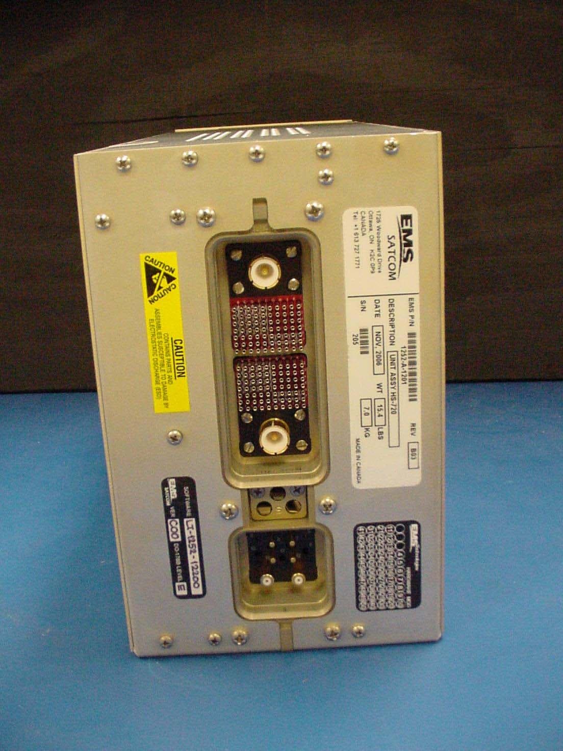
GB8HS-720
Sep 27, 2010High Speed Data Unit for the MCS-7200 SATCOM System
Equipment Class
TNB - Licensed Non-Broadcast Station Transmitter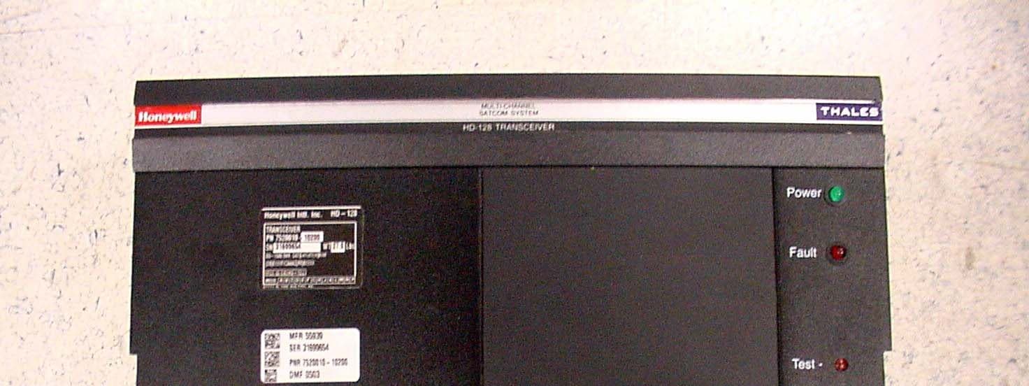
GB8HD-128
Feb 08, 2007SATCOM Transceiver
Equipment Class
TNB - Licensed Non-Broadcast Station Transmitter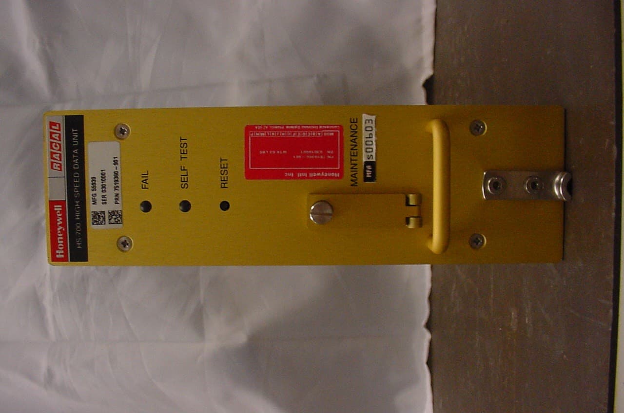
GB8HS-700
Jan 27, 2004Inmarsat Aircraft Telecommunications System
Equipment Class
TNB - Licensed Non-Broadcast Station Transmitter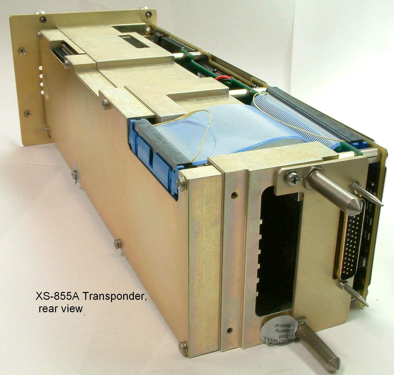
GB8XS855A
Mar 16, 2003UHF Pulsed L Band Transponder
Equipment Class
TNB - Licensed Non-Broadcast Station Transmitter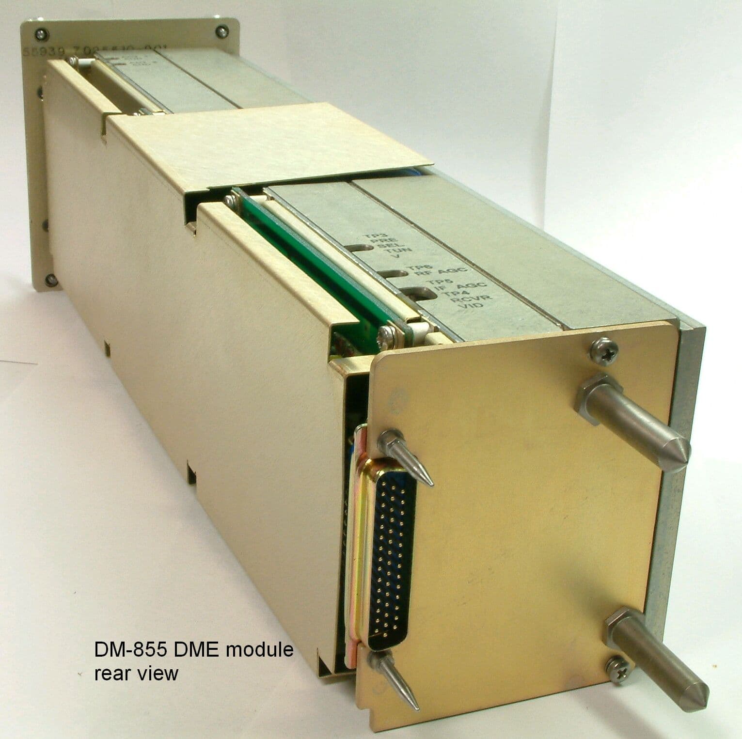
GB8DM855
Mar 12, 2003UHF Pulsed L Band TRX
Equipment Class
TNB - Licensed Non-Broadcast Station Transmitter