GCD-SA02GDoor / Window detector
Rosslare Enterprises Ltd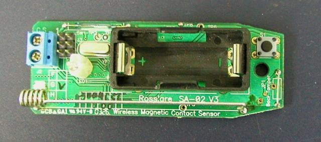
Click to zoom
Application Details
- Equipment Class
- DSC - Part 15 Security/Remote Control Transmitter
- Date of Grant
- Apr 14, 2005
- Application Purpose
- Original Equipment
- Date of Application
- Apr 14, 2005
- Equipment Note
- Door / Window detector
- Frequency Range
- 433.92000000 - 433.92000000
- Company
- Rosslare Enterprises Ltd
- Country
- Hong Kong
Documents & Files
Document Text
Text extracted from the exhibit documents filed with the FCC. Open a document above to read the original.
Users Manual
INSTALLATION INSTRUCTIONS INTRODUCTION (FAQ's) Q: What is a Magnetic Contact Sensor ? A: A Magnetic Contact Sensor is a sensor which detects the opening and closing of doors or windows protected by the sensor. Q: What is WIRELESS and how can it benefit me ? A: Wireless is the use of radio signals to transmit a signal from any sensor to a security panel, eliminating the need for setting wire ducts, extra cabling materials or drilling, saving time and money. Q: What is SUPERVISOR or SUPERVISED sensor ? A: A Supervised sensor continuously reports to the receiver or security panel to confirm status of the sensor and its presence. If the receiver fails to hear from a sensor within a pre-programmed time, it will presume a sensor is missing or malfunctioning and notify the user. This provides added security. Q: What is LOW BATT detection ? A: For all supervised sensors, LOW BATT detection is when a sensor continuously measures its battery state and transmits a low battery signal to the security panel when the battery's voltage drops below a certain level. This alerts the user in advance to replace a weak battery. Q: What is a CASE TAMPER detector? A: A Case Tamper detector monitors any unauthorized opening of the unit housing. A signal will be transmitted to the security panel to notify the user of such tampering. Q: What is a BACK TAMPER detector? A: Once the sensor is mounted and activated, the Back Tamper detector ensures that the sensor is not removed or vandalized by detecting any removal of the unit from a wall or corner. The Back tamper detector will alert the security panel in such cases. FEATURES OF SA-02 - Performance Magnetic Contact Sensor The SA-02 Supervised Wireless Magnetic Contact Sensor is a high-performance intrusion sensor developed with the highest level of technology to make it ideal for residential and commercial applications. Following features standard. Supervisor Case & Back Tamper Detectors ASIC and Microprocessor Technology Up to 3-yr. Battery Life with SPS Ultra-low Current Consumption Readily Replaceable 3.6V- 1/2 AA Lithium Battery SMD Component technology L.E.D. Test Function INSTALLATION - Performance Criteria The SA-02 Magnetic Contact Sensor detects the opening and closing of doors and windows and transmits this information to the receiver panel. - AVOID: Placing the Magnetic Contact Sensor near strong magnetic or electrical fields other than the magnet with which it is intended to be used. Otherwise, performance could be affected and false alarms could occur. - AVOID: Mounting on or near large metal surfaces and multiple concrete/steel walls. This may interfere or block the wireless signals. Make sure to test the range from any location by using the RF Test Procedure to ensure reception. - IMPORTANT NOTE: Install the Magnetic Contact Sensor on windows or doors that have firm hinges and firm locking action to prevent false alarms associated with wind or bumping. STEP-1 INSTALLING THE BATTERY (Fig 1) Use only the specified 3.6 V Lithium Battery. (See block 22) 1) Unscrew the case locking screw and remove the front cover. CAUTION Do not touch the magnetic element or the electronic components inside as this may cause damage. 2) For a new unit, simply remove the plastic strip contact breaker. For replacement, remove the battery by using a small screwdriver. CAUTION: Notice the polarity. Replace with a fresh battery. 3) Dispose of the old battery properly. Do not incinerate, heat, disassemble, recharge. 4) To test, press in both the back-tamper and the case- tamper buttons, or use a magnet to simulate a door opening and closing. The LED will light to indicate an RF transmission. 5) Close the front cover and replace the locking screw FIG 1: Front of PCB FRONT OF PCB BATTERY HOLDER TERMINAL BLOCK FOR WIRED CONTACTS ANTENNA RF TRANSMISSION INDICATION LED CASE TAMPER BUTTON (NORMALLY CLOSED) MAGNETIC CONTACT INTERNAL SENSOR JUMPER FOR EXTERNAL SENSOR STEP-2 SELECTING THE LOCATION The location and mounting of the SA-02 affects both the transmission range and wear and tear of the transmitter. Preferably the transmitter should be installed as close as possible to the receiver and mounted in a high location so that the transmission will have less interference. 1) Select a DOOR OR WINDOW within a room or hallway that best matches the criteria in section 5. (Fig 2): 2) Make sure that the Magnetic Contact Sensor will be mounted on a sturdy, non-vibrating door or window frame. Note: Following this instruction will reduce bumping and vibration effects on the sensor, and will extend the life of the product. 3) Perform the RF Test from the proposed mounting location to ensure that the sensor can be received. 4) Select the appropriate height for the magnet assembly that will suit the location of the sensor. STEP- 4 WIRING THE EXTERNAL SENSOR When the internal magnetic sensor in the SA-02 is not applicable, or an additional set of contacts are needed for the SA-01, the following procedure is required: The maximum distance that an external contact can be away from the SA-02 is about 8.5 meters or 25 feet. 1) This step is not necessary unless installing a remote external magnetic contact sensor with a wire to the SA-02. 2) Remove the case locking screw and front cover. 3) Connect the external magnet(s) in series to the wired input terminal block of the magnetic contact sensor. 4) Move the jumper cover to the two right-most pins to activate the external magnetic contact input. 5) Replace the front cover and locking screw. Please see FIG 4. FIG 4: Wiring an External Sensor + Wired External Magnetic Contact. Terminal Block for External Magnetic Contact. Jumper for activating the external contacts. STEP-3 SELECT MAGNET HEIGHT The SA-02 comes equipped with a standard magnet with adjustable height, suitable for most applications When there is a special need, select the appropriate height for the magnet assembly that will suit the location of the sensor. (FIG 3) To adjust for a possible mis…
Text truncated - open the document above for the full version.
Cover Letter(s)
CONFIDENTIALITY LETTER Federal Communications Commission 7435 Oakland Mills Road Columbia, MD 21046 Gentlemen: This letter is to comply with Section 0.457(d)(2)(i) and 0.459 pertaining to confidential material. ROSSLARE Ltd. would like the following documents regarding this submission for FCC ID: GCD- SA02G to be kept confidential. 1. Pages 1 of 1 of document SA-02G_Radio_Scheme 2. Pages 1 of 1 document SA-02G_Clock_Tree 3. Pages 1 of 1 document SA-02G_Power_Tree. The above material contains trade secrets or technical data, which would customarily be guarded from competitors. We do not want these documents to be accessible to the general public. Sincerely, Company Name: ROSSLARE ENTERPRISES Ltd. Technical Contact: Alan Green Phone: 972-3-9386838 Fax: 972-4-9386830 Email: [email protected] Address: FLAT 12, 9/F WING FAT IND BLDG. 12 WANG TAI RD., KOWLOON BAY. KOWLOON HONG KONG 1/1
Test Report
REV ∆ Description Sheet Effected Date Drawn Checked A 17.03.04 D.Lanuel S.Cohen EMC Laboratory FCCID: GCD-SA02G Manufactured by Rosslare Ltd. EMC Test Report According FCC Part 15 Requirements Feb 2004 Function/Title Name Signature Date Prepared by Test Engineer D.Lanuel 17.03.04 Checked by Test Engineer D.Lanuel 17.03.04 Approved by EMC Lab. Manager S.Cohen 17.03.04 SA-02-G-WINDOWROSSLARE EMI Test Report Table of Contents Para Page 1 INTRODUCTION...............................................................................................................................3 2 TEST SUMMARY AND SIGNATURES...................................................................................................4 3 E.U.T INFORMATION........................................................................................................................5 4 BANDWIDTH OF THE EMISSION PART 15.231—TEST RESULTS...........................................................6 5 FIELD STRENGTH OF FUNDAMENTAL PART 15.231-TEST RESULTS.....................................................7 6 RADIATED EMISSION PART 15.231 & 15.205-TEST RESULTS..............................................................9 7 RADIATED EMISSION PART 15.109-TEST RESULTS..........................................................................13 8 PLOTS...........................................................................................................................................15 EMC/30020FC04039 2/24 SA-02-G-WINDOWROSSLARE EMI Test Report 1 INTRODUCTION a. Scope This document describes the measurement procedures and tests for FCC part 15 of the SA- 02-G-Window Manufactured by Rosslare Ltd. b. Description of equipment Under Test. Equipment Under Test: SA-02-G-Window FCCID FCCID: GCD-SA02G Manufacturer: Rosslare Ltd. Serial Numbers: 3004173 Mode of Operation: TX MODE Receiver operating frequency: 433.92MHZ Year of Manufacture: 2004 c. Applicant Information: Applicant: Rosslare Enterpriser Ltd. Applicant Address FLAT 12, 9/F WING FAT IND BLDG. 12 WANG TAI RD., KOWLOON BAY. KOWLOON HONG KONG Telephone: +972-3-9386838 FAX: +972-3-9386830 The testing was observed by: ALEN GREEN following applicant's personnel: d. Test Performance: Date of reception for testing: 10.03.04 Dates of testing 11.03.04 Test Laboratory Location TADIRAN EMC LAB , Hashoftim 26 Holon 58102 ISRAEL Tel: 972-3-5574476 Fax: 972-3-5575320 Applicable EMC Specification: Federal Communication Commission (FCC), Code of Federal Regulations 47, FCC Docket 89-103,Part 15: Radio Frequency Devices, Sections 15.109, 15.209 & 15.231. EMC/30020FC04039 3/24 SA-02-G-WINDOWROSSLARE EMI Test Report 2 TEST SUMMARY AND SIGNATURES. TADIRAN EMC Laboratory has completed testing of E.U.T in accordance with the requirements of the FCC Part 15 Regulations for Class B equipment. The E.U.T was found to comply with the requirements of the FCC Part 15 Regulations given below Test Test Description Section PASS/FAIL 1 Bandwidth of the emission 15.231 PASS 2 Field strength of fundamental 15.231 PASS 3 Radiation emission 15.109 PASS 4 Radiation emission 15.231 & 15.205 PASS a. Test performed by: Mr. D. Lanuel Test Engineer b. Test Report prepared by: Mr. D. Lanuel Test Engineer c. Test Report Approved by: Mr. Samuel Cohen EMC Lab. Manager EMC/30020FC04039 4/24 SA-02-G-WINDOWROSSLARE EMI Test Report 3 E.U.T INFORMATION a. E.U.T description 1.1 The SA-02 Door/Window Detector is a small door or window frame mounted security device – to be installed in residential and small commercial establishments. 1.2 The SA-02 is a stand-alone unit, operating only on internal battery power supply. The unit consists of one (1) PCB, one (1) microcontroller – which controls the detector operation, and a RF transmitter section. The unit does not have a RF receiver section. 1.3 The SA-02 Door/Window Detector has one RF channel, at 433.92 Mhz carrier with OOK modulation. 1.4 The SA-02 Door/Window Detector in active mode transmits identification and status signals in 100ms. A supervisory transmission from the SA-02 to the control panel occurs for the same time of one transmission (100 ms), every 20 minutes per hour. 1.5 The battery used is 3vdc lithium, CR123A - replaceable. b. E.U.T Test Configuration E.UT. test configuration is shown in figure bellow Internal Battery Integral Antenna E.U.T c. E.U.T Mode of Operation description (1) 433.92MHz TX Mode operated by battery EMC/30020FC04039 5/24 SA-02-G-WINDOWROSSLARE EMI Test Report 4 BANDWIDTH OF THE EMISSION PART 15.231—TEST RESULTS E.U.T: SA-02-G-WINDOW S/N 3004173 Test Method: ANSI 63.4 Date: 02/06/03 Relative Humidity: 30% Ambient Temperature: 22c Air Pressure: 1050hpa Test Setup: Figure 1 Testing Engineer: D.Lanuel Date 11/03/04 a. Test Results Summary & Conclusions The E.U.T was found in compliance with Bandwidth of Radiated Emission fundamental frequency requirement b. Limits of bandwidth The test unit shall meet the limits of Table 1 TABLE- 1 Limits For Bandwidth Frequency (MHz) Bandwidth Max Limits (%) Bandwidth Max Limits (KHz) 433.92 0.25 1085 c. Test Instrumentation and Equipment TABLE- 2 Test Instrumentation and Equipment Item Model Manufacturer Next Date Calibration Spectrum Analyzer 8593E HP 31/01/05 Broadband Antenna BTA-L FRANKONIA 10.04.06 d. Test Results TABLE- 3 Bandwidth Test Result Frequency (MHz) Bandwidth (KHz) Bandwidth Max Limit(KHz) Plot No PASS/ FAIL 433.92 52.5 1085 Plot-1 PASS e. Procedure The Bandwidth is determined at the point 20db down from the modulated carrier, while the spectrum analyzer was set to “max hold” and R.BW –10KHz. EMC/30020FC04039 6/24 SA-02-G-WINDOWROSSLARE EMI Test Report 5 FIELD STRENGTH OF FUNDAMENTAL PART 15.231-TEST RESULTS E.U.T: SA-02-G-WINDOW S/N 3004173 Test Method: ANSI 63.4 Date: 09/06/03 Relative Humidity: 30% Ambient Temperature: 22c Air Pressure: 1050hpa Test Setup: Figure 1 Testing Engineer: D.Lanuel Date 11/03/04 a. Test Results Summary & Conclusions The E.U.T was found in compliance with fundamental frequen…
Text truncated - open the document above for the full version.
Test Setup Photos
FCC ID: GCD-SA02G Subject: SETUP PICTURES for SA-02G FCC ID:GCD-SA02G Radiated Emission Test Setup Radiated Emission Test Setup
Contact Information
Applicant
Ilan Ozer(Director)
Test Firm
Elbit Systems Land C41Tadiran Ltd.Samuel Cohen
Technical Specifications
| # | Rule Parts | Frequency Range | Power Output |
|---|---|---|---|
| 1 | 15.231 | 433.92 MHz - 433.92 MHz | - |
Other Applications from Rosslare Enterprises Ltd

GCD-AYK35
Aug 01, 2021Multi-Smart Readers
Equipment Class
DTS - Digital Transmission System
GCD-HLX24TH
Jan 27, 2016Advanced Wireless Security Panels
Equipment Class
DSC - Part 15 Security/Remote Control Transmitter
GCD-HLX24TG
Jan 27, 2016Advanced Wireless Security Panels
Equipment Class
DSC - Part 15 Security/Remote Control Transmitter
GCDAYXX0
Sep 20, 2015Reader
Equipment Class
DCD - Part 15 Low Power Transmitter Below 1705 kHz
GCDAYQX0
Sep 20, 2015Reader
Equipment Class
DCD - Part 15 Low Power Transmitter Below 1705 kHz