GCD-SA04GPanic Button Remote Control
Rosslare Enterprises Ltd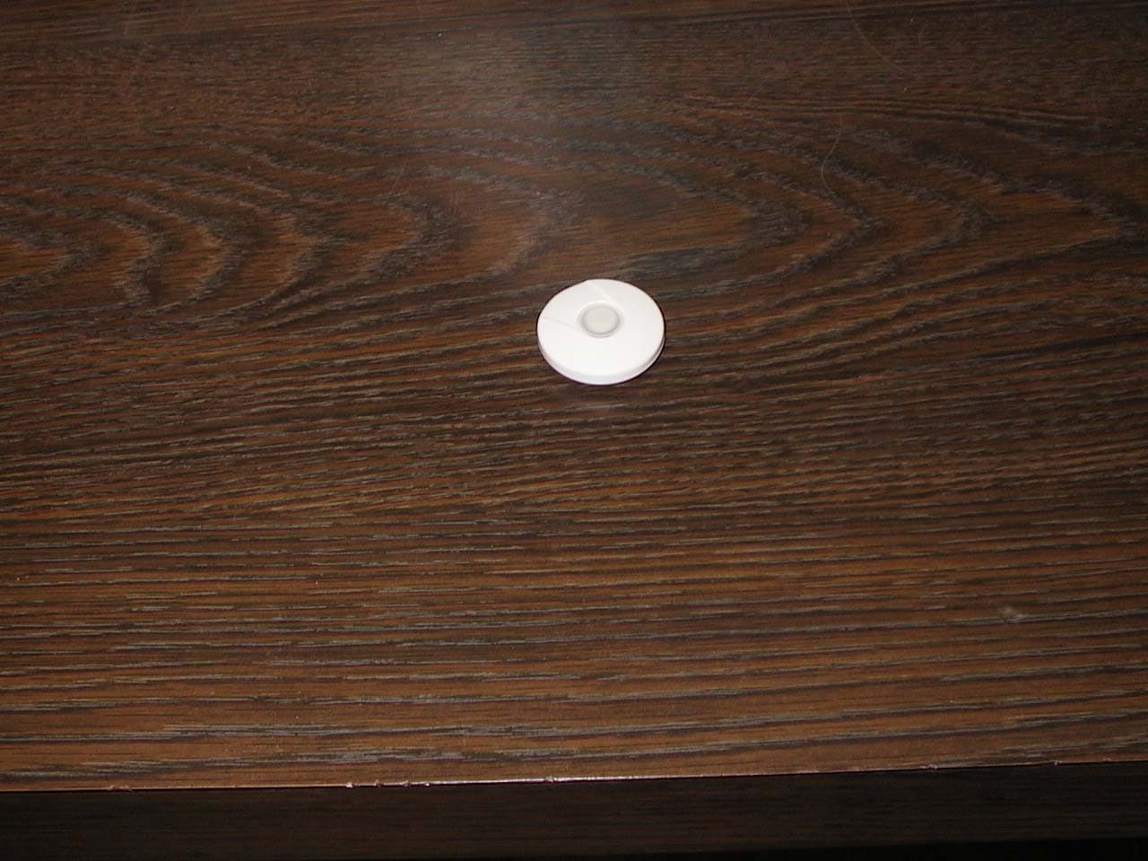
Click to zoom
Application Details
- Equipment Class
- DSC - Part 15 Security/Remote Control Transmitter
- Date of Grant
- May 05, 2005
- Application Purpose
- Original Equipment
- Date of Application
- May 05, 2005
- Equipment Note
- Panic Button Remote Control
- Frequency Range
- 433.92000000 - 433.92000000
- Company
- Rosslare Enterprises Ltd
- Country
- Hong Kong
Documents & Files
Document Text
Text extracted from the exhibit documents filed with the FCC. Open a document above to read the original.
Users Manual
Wireless Panic Button Transmitter Q: What is a Transmitter ? A: A transmitter is an electronic device that uses RF energy and coded digital messages to control and communicate commands to other electronic products. Q: What is SA-04 PANIC BUTTON and how can it benefit me ? A: SA-04 allows the user to set off the security system alarm with just a press of the button, when in a dangerous situation or in need of help, through the Control Panel. Q: What is SUPERVISOR or SUPERVISED sensor ? A: A Supervised sensor continuously reports to the receiver or security panel to confirm status of the sensor and its presence. If the receiver fails to hear from a sensor within a pre-programmed time, it will presume a sensor is missing or malfunctioning and notify the user. This provides added security. INTRODUCTION (FAQ's) - continued; OPERATION - GENERAL NOTES The SA-04 is a miniature radio transmitter, designed to send coded RF transmissions to wireless receivers and control panels. The transmissions are activated by depressing the pushbutton on the unit. The SA-04 Panic Button is a new addition to the Rosslare’s wireless line, used for individuals who need to feel additional protection fro their security system. The SA-04 provides immediate access to the system, causing an alarm to be announced with the push of a single-button. MAIN FEATURES * Lightweight and easily transported with two types methods of carrying. * Long-range: provides security up to 100 meters from the base. * One-button operation: quick access in the event of an emergency. * Hermetically-sealed unit, against dust and water - perfect for all-weather use, around the premises. AND IMPORTANT INFORMATION INSTALLATION INSTRUCTIONS P/N: 9J-REL-xxx-xxxxxxxx-xx This product may be sold in the following member states of the European Community: AustriaGermany Norway BelgiumGreecePortugal DenmarkHollandSpain FinlandIrelandSweden FranceItalyUnited Kingdom ! GENERAL DESCRIPTION INTRODUCTION (FAQ's) Q: What is LOW BATTERY detection ? A: For all supervised sensors, LOW BATTERY detection is when a sensor continuously measures its battery state and transmits a low battery signal to the security panel when the battery's voltage drops below a certain level. This alerts the user in advance to replace a weak battery. Q: What is a CASE TAMPER detector? A: A Case Tamper detector monitors any unauthorized opening of the unit housing. A signal will be transmitted to the security panel to notify the user of such tampering. Q: What is a BACK TAMPER detector ? A: Once the sensor is mounted and activated, the Back Tamper detector ensures that the sensor is not removed or vandalized by detecting any removal of the unit from a wall or corner. The Back tamper detector will alert the security panel in such cases. The SA-04 remote control is activated by pressing the buttons on the unit and transmits this information to the receiver panel. Since the SA-04is a portable wireless device and system reception is dependent upon the conditions of use as follows: - AVOID: Placing the SA-04 near strong magnetic or electrical fields other than the magnet with which it is intended to be used. Otherwise, performance could be affected and false alarms could occur. - AVOID: Using near or behind large metal surfaces and multiple concrete/steel walls. This may interfere or block the wireless signals. Make sure to test the range from the desired location by using the RF Test Procedure to ensure reception. - AVOID: Submerging in water. 1 23 4 56 7 89 SA-04 Instruction Manual - Version 1.0 (Page 1/1) WARRANTY 10 1112 INTERNATIONAL OFFICES U.S.A.:Rosslare America Inc. Westlake, Los Angeles, CA 91632 U.S.A Tel: (818) 707 2974 Fax: (818) 7070543 Rosslare America Inc. 2001 Reliance, Packway, Suite D Bedford, Texas 76021 U.S.A Tel: (817) 685 9100 Fax: (817) 685 9188 Rosslare Powerpath NAPDC. North America Product Development 22e. Howard St, # 238 Des Plaines, IL60018, U.S.A Tel: (847) 827 6330 Fax: (847) 8276433 ISRAELRosslare Israel Ltd (Center Office) 22 Hamelacha St, PO BOX 11407, Rosh Ha-Ayin, 48091, Hong Kong:Rosslare Enterprises Ltd. 905-912 Wing Fat Industrial Building 12 Wang Tai Road, Kowloon Bay, Hong Kong. Tel (852) 2795 5630 Tel (852) 2795 1508 www.rosslare.com.hk The Manufacturer's warranty on this product is for a period of one year from the date of manufacture against defects in materials and workmanship. Manufacturer's warranty hereunder is limited to repair or replacement, at the manufacturer's sole option, if the product is found to be defective in normal use during the warranty period. The warranty is given in favor of the original purchase only. Subject to the above warranty, manufacturer's liability and that of it's distributors, re-sellers and agents and is wholly limited to the original purchase price and no payment will be made for related or consequential loss including but not limited to labor costs incurred in inspection, replacement or repair of defective products. This warranty is given expressly and in place of all other expressed or implied warranties of merchantability and fitness for a particular purpose and this warranty is the only warranty made by the manufacturer. No agent, representatives or employee of the manufacturer has the authority to waive, alter or add to the printed provisions of this warranty, to make representation of warranty not contained herein or to extend this warranty to anyone other than the original purchaser of the product. The SA-01 PIR is guaranteed against defects in workmanship and material for a period of 12 (Twelve) months from date of purchase. Return the faulty product with a dated proof of purchase to your dealer for replacement. NOTICE The SA-04 is designed to send an electronic signal to alarm control system, should intrusion occur, the warranty does not make the manufacturer or the distributor of the SA-01 PIR held liable for consequential damages resulting from any breech of warranty, expressed or implied, applicable to …
Text truncated - open the document above for the full version.
Users Manual
10.04.05 Attached to the instruction manual for SA-04G Panic Button Remote Control Changes or modifications not expressly approved by the party responsible for compliance could void the user's authority to operate the equipment. Company Name: ROSSLARE ENTERPRISES Ltd. Technical Contact: Alan Green Phone: 972-3-9386838 Fax: 972-4-9386830 Email: [email protected] Address: FLAT 12, 9/F WING FAT IND BLDG. 12 WANG TAI RD., KOWLOON BAY. KOWLOON HONG KONG
Cover Letter(s)
CONFIDENTIALITY LETTER Federal Communications Commission 7435 Oakland Mills Road Columbia, MD 21046 Gentlemen: This letter is to comply with Section 0.457(d)(2)(i) and 0.459 pertaining to confidential material. ROSSLARE Ltd. would like the following documents regarding this submission for FCC ID: GCD- SA04G to be kept confidential. 1. Pages 1 of 1 of document SA-04G_Radio_Scheme 2. Pages 1 of 1 document SA-04G_Clock_Tree 3. Pages 1 of 1 document SA-04G_Power_Tree. The above material contains trade secrets or technical data, which would customarily be guarded from competitors. We do not want these documents to be accessible to the general public. Sincerely, Company Name: ROSSLARE ENTERPRISES Ltd. Technical Contact: Alan Green Phone: 972-3-9386838 Fax: 972-4-9386830 Email: [email protected] Address: FLAT 12, 9/F WING FAT IND BLDG. 12 WANG TAI RD., KOWLOON BAY. KOWLOON HONG KONG 1/1
External Photos
FCC ID: GCD-SA04G Subject: INTERNAL AND EXTERNAL PICTURES for SA-04G 1/4
ID Label/Location Info
Rosslare Security Products FCC product label guide Panic Button Remote Control SA-04G 433.92MHz FCC ID: GCD-SA04G This device complies with Part 15 of the FCC rules. Operation is subject to the following two conditions: 1) This device may not cause harmful interference, and 2) This device must accept any interference received, including interference that may cause undesired operation. The label is located on the bottom of the device
Internal Photos
2/4 3/4 4/4
Operational Description
FCC ID: GCD-SA04G OPERATIONAL DESCRIPTION 1.Operational Description The RF section of the SA04G is based on a Melexis chip with a fixed modulus (32) PLL. Thus the 13.56 MHz Xtal is multiplied by 32 giving the 433.92 MHz carrier frequency. A balanced output is matched by a passive network that can deliver up to +2 dBm into 50 OHM. This device is followed by a passive antenna matching network. A printed antenna is situated on the PCB. The u-Controller provides two signals. Namely a chip enable line that activates the Melexis and the PA and a data line that is used to OOK modulate both the Melexis device 2. Timing Requirements When the Panic Button Remote Control detects activity 5 identical transmissions are sent. The time between the end of one transmission and the start of the subsequent one being random. This time interval varies between 105ms and 400 ms. However, the total TX period is always less than 1 s. 1/2 1. START BIT 312uS 1248uS 624uS 312uS 1. PREAMBLE 1. DATA 208uS ID2ID3 CRC FAMILY DATA 208uS ID1 4 BIT 0 1 MOST 4BIT RESERVED TOTAL BITS PER SUB FRAME: 48 TOTAL SUB FRAME DATA TIME: 19.968mS TOTAL SUB FRAME TIME: 21.842Ms RANDOM SUB FRAMES 4 TIME SLOTS TOTAL SUB FRAMES IN SUPER FRAME: 5 208uS 208uS 2/2
Test Report
REV ∆ Description Sheet Effected Date Drawn Checked A 17.03.04 D.Lanuel S.Cohen EMC Laboratory FCCID: GCD-SA04G Manufactured by Rosslare Ltd. EMC Test Report According FCC Part 15 Requirements Feb 2004 Function/Title Name Signature Date Prepared by Test Engineer D.Lanuel 17.03.04 Checked by Test Engineer D.Lanuel 17.03.04 Approved by EMC Lab. Manager S.Cohen 17.03.04 SA-04G Panic ROSSLARE EMI Test Report Table of Contents Para Page 1 INTRODUCTION...............................................................................................................................3 2 TEST SUMMARY AND SIGNATURES...................................................................................................4 3 E.U.T INFORMATION........................................................................................................................5 4 BANDWIDTH OF THE EMISSION PART 15.231—TEST RESULTS...........................................................6 5 FIELD STRENGTH OF FUNDAMENTAL PART 15.231-TEST RESULTS......................................................7 6 RADIATED EMISSION PART 15.231 & 15.205-TEST RESULTS..............................................................9 7 RADIATED EMISSION PART 15.109-TEST RESULTS..........................................................................13 8 PLOTS...........................................................................................................................................15 EMC/30020FC04041 2/23 SA-04G Panic ROSSLARE EMI Test Report 1 Introduction a. Scope This document describes the measurement procedures and tests for FCC part 15 of the SA-04- G-Panic Manufactured by Rosslare Ltd. b. Description of equipment Under Test Equipment Under Test: SA-04G Panic Button Remote Control FCCID GCD-SA04G Manufacturer: Rosslare Ltd. Serial Numbers: 3003722 Mode of Operation: TX MODE Receiver operating frequency: 433.92MHZ Year of Manufacture: 2004 c. Applicant Information: Applicant Address FLAT 12, 9/F WING FAT IND BLDG. 12 WANG TAI RD., KOWLOON BAY. KOWLOON HONG KONG Applicant Address 22, Hamelachal Street Rosh-Ha-ayin Telephone: +972-3-9386838 FAX: +972-3-9386830 The testing was observed by: ALEN GREEN Following applicant's personnel: d. Test Performance: Date of reception for testing: 10.03.04 Dates of testing 11.03.04 Test Laboratory Location TADIRAN EMC LAB , Hashoftim 26 Holon 58102 ISRAEL Tel: 972-3-5574476 Fax: 972-3- 5575320 Applicable EMC Specification: Federal Communication Commission (FCC), Code of Federal Regulations 47, FCC Docket 89-103,Part 15: Radio Frequency Devices, Sections 15.109, 15.209 & 15.231. EMC/30020FC04041 3/23 SA-04G Panic ROSSLARE EMI Test Report 2 Test Summary and Signatures. TADIRAN EMC Laboratory has completed testing of E.U.T in accordance with the requirements of the FCC Part 15 Regulations for Class B equipment. The E.U.T was found to comply with the requirements of the FCC Part 15 Regulations given below Test Test Description Section PASS/FAIL 1 Bandwidth of the emission 15.231 PASS 2 Field strength of fundamental 15.231 PASS 3 Radiation emission 15.109 PASS 4 Radiation emission 15.231 & 15.205 PASS a. Test performed by: Mr. D. Lanuel Test Engineer b. Test Report prepared by: Mr. D. Lanuel Test Engineer c. Test Report Approved by: Mr. Samuel Cohen EMC Lab. Manager EMC/30020FC04041 4/23 SA-04G Panic ROSSLARE EMI Test Report 3 E.U.T Information a. E.U.T description (1) The SA-04 Panic Button Remote Control is a small handheld remote control transmitter worn by the user, to activate the security system in times of emergency. (2) The SA-04 Panic Button Remote Control is a stand-alone unit, operating only on internal battery power supply. The unit consists of one (1) PCB, one (1) microcontroller – which controls the detector operation, and a RF transmitter section. The unit does not have a RF receiver section. (3) The SA-04 Panic Button Remote Control has one RF channel, at 433.92 Mhz carrier with OOK modulation. (4) The SA-04 Panic Button Remote Control in active mode transmits identification and status signals in 100ms. No supervisory signal is transmitted from the device. (5) When the Remote Control detects activity 5 identical transmissions are sent. The time between the end of one transmission and the start of the subsequent one being random. This time interval varies between 105ms and 400 ms. However, the total TX period is always less than 1 s. (6) The battery used is a 3vdc non-replaceable lithium. b. E.U.T Test Configuration E.UT. test configuration is shown in figure bellow Internal Battery Integral Antenna E.U.T c. E.U.T Mode of Operation description (1) 433.92MHz TX Mode operated by battery EMC/30020FC04041 5/23 SA-04G Panic ROSSLARE EMI Test Report 4 BANDWIDTH OF THE EMISSION part 15.231—TEST RESULTS E.U.T: SA-04-G-PANIC S/N 3003722 Test Method: ANSI 63.4 Date: 11/03/04 Relative Humidity: 29% Ambient Temperature: 21c Air Pressure: 1053hpa Test Setup: Figure 11 Testing Engineer: D.Lanuel Date 17/03/04 a. Test Results Summary & Conclusions The E.U.T was found in compliance with Bandwidth of Radiated Emission fundamental frequency requirement b. Limits of bandwidth The test unit shall meet the limits of Table 1 TABLE- 1 Limits For Bandwidth Frequency (MHz) Bandwidth Max Limits (%) Bandwidth Max Limits (KHz) 433.92 0.25 1085 c. Test Instrumentation and Equipment TABLE- 2 Test Instrumentation and Equipment Item Model Manufacturer Next Date Calibration Spectrum Analyzer 8593E HP 31/01/05 Broadband Antenna BTA-L FRANKONIA 10.04.06 d. Test Results TABLE- 3 Bandwidth Test Result Frequency (MHz) Bandwidth (KHz) Bandwidth Max Limit (KHz) Plot No PASS /FAIL 433.92 55.5 1085 Plot-1 PASS e. Procedure The Bandwidth is determined at the point 20db down from the modulated carrier, while the spectrum analyzer was set to “max hold” and VBW –10KHz. EMC/30020FC04041 6/23 SA-04G Panic ROSSLARE EMI Test Report 5 field strength of fundamental part 15.231-TEST RESULTS E.U.T: SA-04-G-PANIC S/N 3003722 Test Method: A…
Text truncated - open the document above for the full version.
Test Setup Photos
FCC ID: GCD-SA04G Subject: SETUP PICTURES for SA-04G FCC ID:GCD-SA04G Radiated Emission Test Setup SA-01-G-PIR ROSSLARE EMI Test Report Radiated Emission Test Setup EMC/30020FC04038 2/ 2
Contact Information
Applicant
Ilan Ozer(Director)
Test Firm
Elbit Systems Land C41Tadiran Ltd.Samuel Cohen
Technical Specifications
| # | Rule Parts | Frequency Range | Power Output |
|---|---|---|---|
| 1 | 15.231 | 433.92 MHz - 433.92 MHz | - |
Other Applications from Rosslare Enterprises Ltd

GCD-AYK35
Aug 01, 2021Multi-Smart Readers
Equipment Class
DTS - Digital Transmission System
GCD-HLX24TH
Jan 27, 2016Advanced Wireless Security Panels
Equipment Class
DSC - Part 15 Security/Remote Control Transmitter
GCD-HLX24TG
Jan 27, 2016Advanced Wireless Security Panels
Equipment Class
DSC - Part 15 Security/Remote Control Transmitter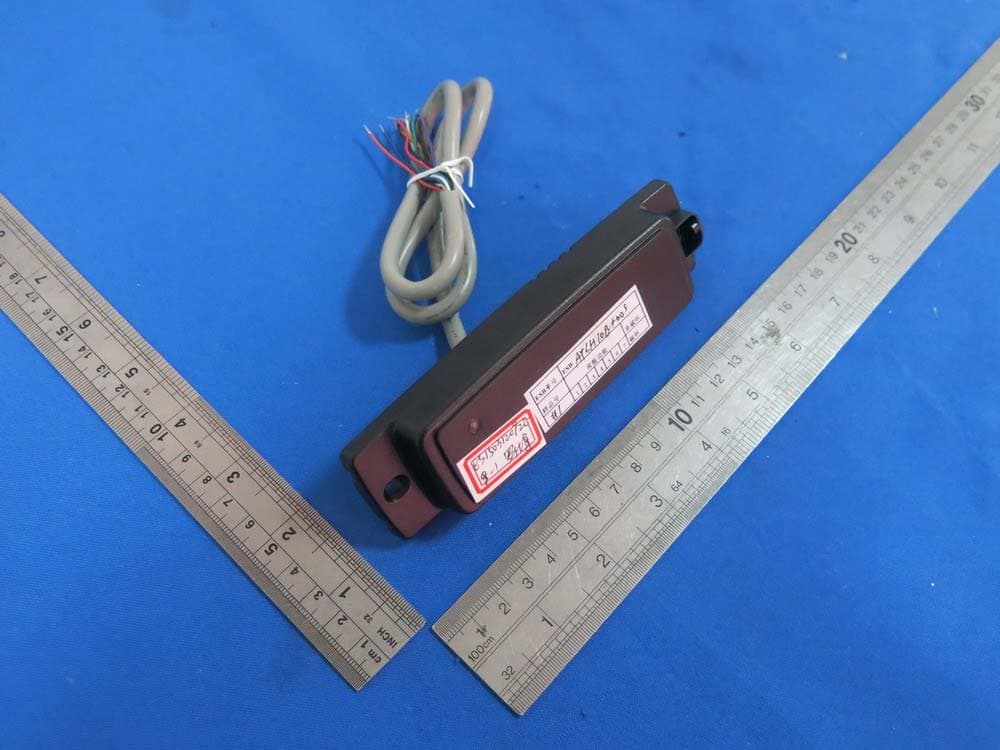
GCDAYXX0
Sep 20, 2015Reader
Equipment Class
DCD - Part 15 Low Power Transmitter Below 1705 kHz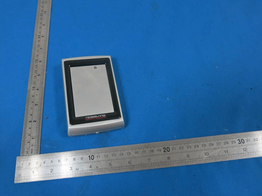
GCDAYQX0
Sep 20, 2015Reader
Equipment Class
DCD - Part 15 Low Power Transmitter Below 1705 kHz