GCD10F302ProximityCard Reader used for Access Control
Rosslare Enterprises Ltd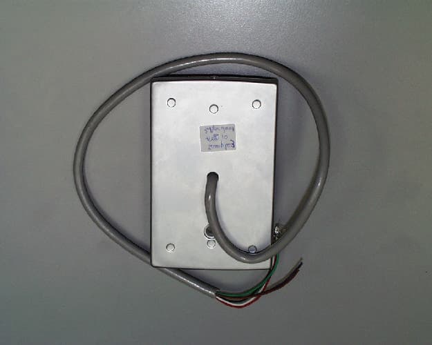
Click to zoom
Application Details
- Equipment Class
- DCD - Part 15 Low Power Transmitter Below 1705 kHz
- Date of Grant
- Sep 09, 2001
- Application Purpose
- Original Equipment
- Date of Application
- Sep 09, 2001
- Equipment Note
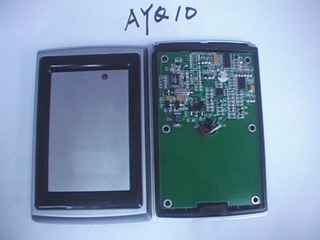
- ProximityCard Reader used for Access Control
- Frequency Range
- 0.12500000 - 0.12500000
- Company
- Rosslare Enterprises Ltd
- Country
- Hong Kong
Documents & Files
Document Text
Text extracted from the exhibit documents filed with the FCC. Open a document above to read the original.
Users Manual
K5336 Rev. 6, 07/2001 -1- OmniProx™ Reader Model Series OP10/20/30/40/45/90 Installation Instructions WHAT IS THE ADEMCO OmniProx™ READER? The OmniProx Reader is an RFID proximity card reader to be installed for use with access control systems. These installation instructions contain the following information: • Mounting Instructions • Connecting the reader to the host • Testing and operation of the reader Visit www.omniprox.com for the latest information and technical support. HOW TO MOUNT THE READER Figure 1 shows the front view of the OmniProx. When mounting models OP10/20/30/40/45, the snap-off cover must be removed to access the screw holes. The model OP90 uses a security screw on the bottom of the reader to secure the cover. Remove this security screw using the supplied tool. Then slide the back plate down slightly and then lift it up from the bottom. Select the desired mounting holes and drill them out. Mount the reader with the appropriate screws (not supplied) as indicated on the template. To surface mount the reader, perform the following: 1. Determine an appropriate mounting position for the reader. 2. Peel off the back of the self-stick mounting label template included with the unit and place at the desired mounting position. (Additional templates can be downloaded from www.omniprox.com.) 3. Using the template as a guide, drill two holes (hole size is indicated on mounting template) for mounting the reader to the surface. 4. Drill a 1/2” (13 mm) hole for the cable. If mounting on metal, place a grommet or electrical tape around the edge of the hole. 5. Route the interface cable from the reader and/or power supply to the host. A linear type power supply is recommended. Check all electrical codes for proper installation. U L Card Reader Models OP10/20/30/40/45/90 are to be used with control panels whose power supply is UL listed Class 2 or equivalent. HOW TO CONNECT THE READER TO THE HOST The OmniProx Reader is supplied with an 18-inch pigtail, having a 6-conductor cable. To connect the reader to the host, perform the following steps: 1. Prepare both the reader cable and host cables by cutting the cable jacket back 1¼ inches and strip the wires ½ inch. 2. Splice the reader pigtail wires to the corresponding host wires and cover each connection (see Figure 2). 3. If the tamper output is being utilized, connect the purple wire to the correct input on the host. 4. Trim and cover all conductors that are not used. Figure 2 below shows how you should wire the reader to the host. Wiring Notes: 1. The individual wires coming out of the reader are color coded according to the recommended Wiegand standard. 2. If either 5 or 12 volts are available, use 12 volts for better performance. 3. When using a separate power suppl y for the reader, the reader, power supply and host must have a common ground. 4. The recommended cable depends on the distance from the reader to the host. See Table 1 on the next page for the correct wire gage based upon distance. Larger wire gauges are acceptable. The wire must be stranded with an overall shield, either foil or braided. If the tamper is not being used, 5 conductor cable is required; otherwise 6 Figure 2 Figure -2- conductor cable is required. 5. The cable shield wire on the reader should be attached to an Earth ground (best) or signal ground connection at the panel or power supply end of the cable. This configuration is best for shielding the reader cable from external interference. TABLE 1: WIRE GAGE SPECIFICATIONS Distance Gage 5 Conductor 6 Conductor 200 ft. (61m) 22 Alpha 1295C Alpha 1296C 300 ft. (91m) 20 Alpha 58126 Alpha 58126 500 ft. (153 m) 18 Alpha 58136 Alpha 58136 Note: Recommended cable is only a guideline, use any manufacturer that meets the gage and shield specifications. HOW TO TEST AND OPERATE THE READER The reader should be tested after wiring it to a power supply and the host. Do this by performing the following steps: 1. Power up the reader. The LED and beeper will activate three times. This indicates that the reader is working properly. 2. Present the appropriate type of ID card to the reader. (See Table 2 for the correct card type based on the reader model.) The LED will momentarily flash green and a short beep will be emitted. This indicates that the card was read properly by OmniProx. 3. After the card data is processed by the host, the host can then turn the LED green or yellow. Refer to the host description of the LED operation if the reader LED is controlled by the host. Table 2: Model Number vs. Feature Matrix Model Number UL Listing Part # Card Type Output Format Read Range (Max.) * OP10-FW AY-K10 HID Wiegand 3” OP10-AW AY-K12 ADEMCO Wiegand 3” OP20-FW AY-J10 HID Wiegand 4” OP20-AW AY-J12 ADEMCO Wiegand 4” OP30-FW AY-L10 HID Wiegand 5” OP30-AW AY-L12 ADEMCO Wiegand 5” OP40-FW AY-H10 HID Wiegand 4” OP40-AW AY-H12 ADEMCO Wiegand 4” OP45-FW AY-M10 HID Wiegand 4” OP45-AW AY-M12 ADEMCO Wiegand 4” OP90-FW AY-Qxx HID Wiegand 1.5” Model Number UL Listing Part # Card Type Output Format Read Range (Max.) * TABLE 1: WIRE GAGE SPECIFICATIONS Distance Gage 5 Conductor 6 Conductor 200 ft. (61m) 22 Alpha 1295C Alpha 1296C 300 ft. (91m) 20 Alpha 58126 Alpha 58126 500 ft. (153 m) 18 Alpha 58136 Alpha 58136 Note: Recommended cable is only a guideline, use any manufacturer that meets the gage and shield specifications. HOW TO TEST AND OPERATE THE READER The reader should be tested after wiring it to a power supply and the host. Do this by performing the following steps: 1. Power up the reader. The LED and beeper will activate three times. This indicates that the reader is working properly. 2. Present the appropriate type of ID card to the reader. (See Table 2 for the correct card type based on the reader model.) The LED will momentarily flash green and a short beep will be emitted. This indicates that the card was read properly by OmniProx. 3. After the card data is processed by the host, the host can then turn the LED green or yell…
Text truncated - open the document above for the full version.
Cover Letter(s)
FCC ID: GCD10F301 Request for Confidentiality In accordance with 47 C.F.R. Section 0.459, we, Rosslare Enterprises, Ltd., hereby request confidentiality for the block diagram, schematic and product description presented for certification. In support of the Request for Confidentiality, the following is stated: Enclosed within this application is technical information which we deem to be trade secrets and proprietary. If made public, the information might be used to our disadvantage. To assist in assuring that we receive the full value of our product and protect its competitive posture, we respectfully request this grant of confidentiality. Rosslare Enterprises, Ltd.
Contact Information
Applicant
Ilan Ozer(Director)
Technical Contact
Rosslare Enterprises, LTD.Joe LeKostaj
1 852 2795-5630
200 E. Howard Street · Des Plaines, Illinois · United States
Test Firm
Elite Electronic Engineering Co.Daniel Crowder
Technical Specifications
| # | Rule Parts | Frequency Range | Power Output |
|---|---|---|---|
| 1 | 15C | 0.125 MHz - 0.125 MHz | - |
Other Applications from Rosslare Enterprises Ltd

GCD-AYK35
Aug 01, 2021Multi-Smart Readers
Equipment Class
DTS - Digital Transmission System
GCD-HLX24TH
Jan 27, 2016Advanced Wireless Security Panels
Equipment Class
DSC - Part 15 Security/Remote Control Transmitter
GCD-HLX24TG
Jan 27, 2016Advanced Wireless Security Panels
Equipment Class
DSC - Part 15 Security/Remote Control Transmitter
GCDAYXX0
Sep 20, 2015Reader
Equipment Class
DCD - Part 15 Low Power Transmitter Below 1705 kHz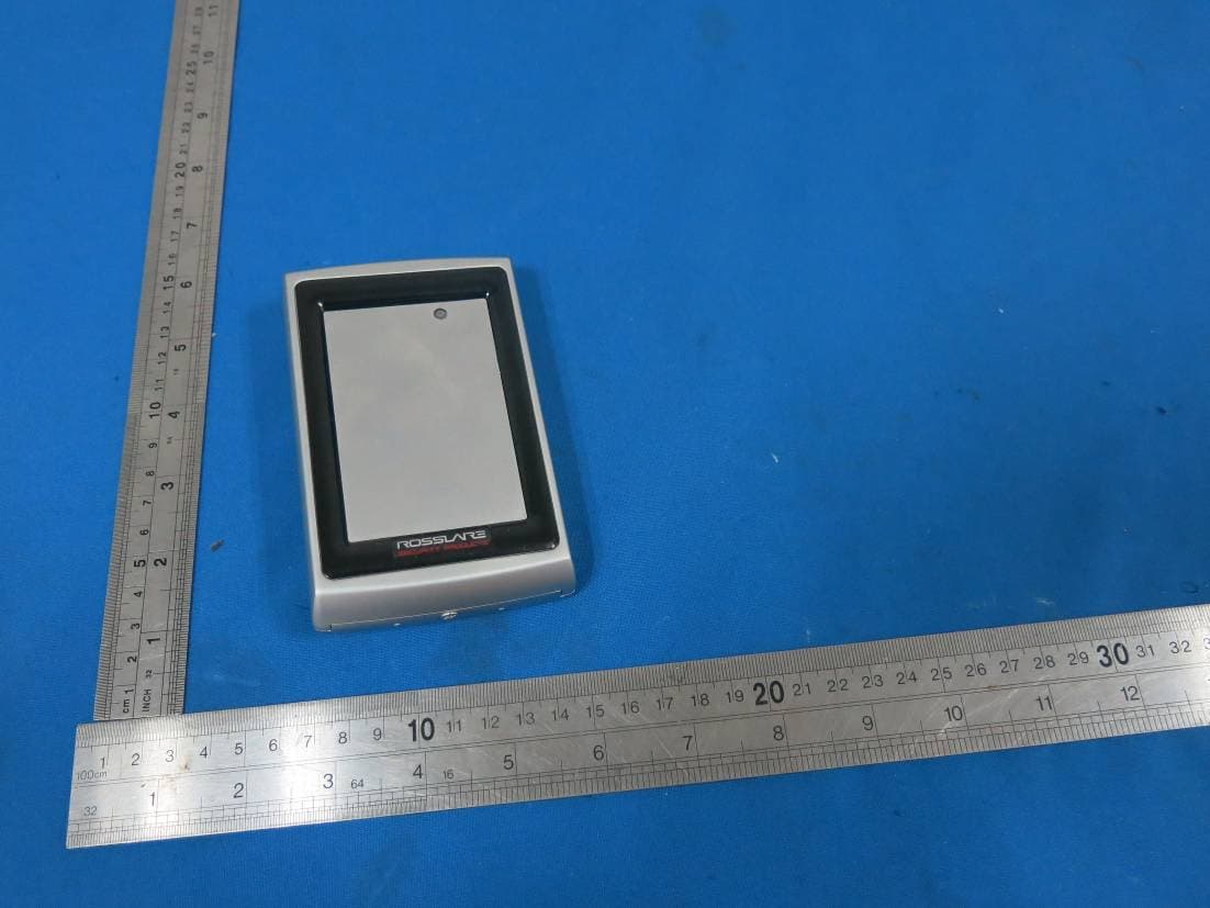
GCDAYQX0
Sep 20, 2015Reader
Equipment Class
DCD - Part 15 Low Power Transmitter Below 1705 kHz