GCD20A302Proximity Card Reader used for access control
Rosslare Enterprises Ltd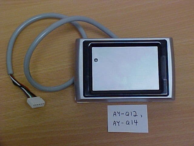
Click to zoom
Application Details
- Equipment Class
- DCD - Part 15 Low Power Transmitter Below 1705 kHz
- Date of Grant
- Apr 24, 2002
- Application Purpose
- Original Equipment
- Date of Application
- Apr 24, 2002
- Equipment Note
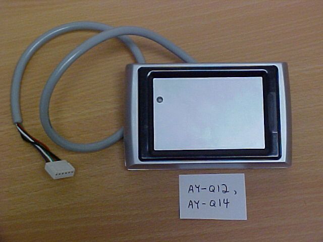
- Proximity Card Reader used for access control
- Frequency Range
- 0.12500000 - 0.12500000
- Company
- Rosslare Enterprises Ltd
- Country
- Hong Kong
Documents & Files
Document Text
Text extracted from the exhibit documents filed with the FCC. Open a document above to read the original.
Users Manual
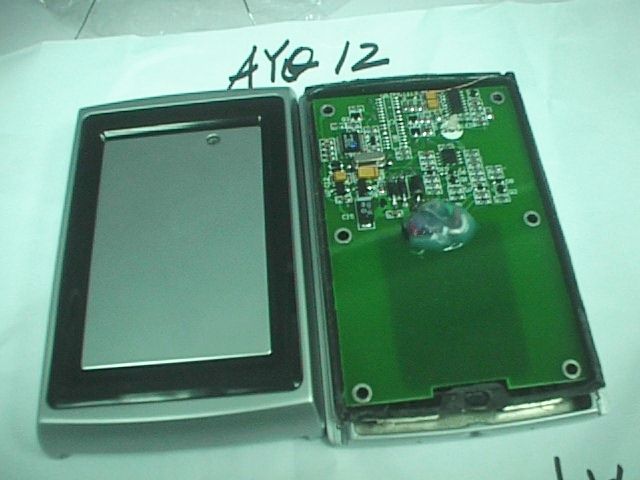
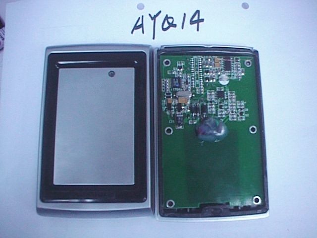
Rosslare Installation Instructions Model Series AY-Q12 03/02 MOUNTING INSTRUCTIONTo mount the Reader, perform the following: Determine an appropriate mounting position for the Reader.Peel off the back of the self-stick mounting label templateincluded with the unit and place at the desired mounting position.Using the template as a guide, drill two holes (hole size isindicated on mounting template) for mounting the Reader to thesurface. Drill a 7/16" (10mm) hole for the cable. If mounting onmetal, place a grommet around the edge of the hole.Remove the case screw and slide the rear case away from the frontcase. (See diagram below)Drill holes into the back of the rear metal case according to howyou want to mount the reader. (See Diagram below)Attach the reader to the controller.Screw the readers rear case to its mounting location and return thefront case onto the mounted rear case.Secure the front cover by using the supplied security screw in thecontrollers accessories kit. An L-Shaped tool is provided for usewhen tightening the security screw. 1.2.3.4.5.6.7.8. After the card data is processed by the Controller, the Controllercan then turn the LED green. Refer to the Controller descriptionof the LED operation if the Reader LED is controlled by theController. 3. -1- Measured using Rosslare Proximity Card (P/N AT-11/14) orequivalent. Range also depends on electrical environment and/orproximity to metal. * Figure 2 WIRING INSTRUCTIONThe Prox Reader is supplied with an 18-inch pigtail, having a 6-conductor cable. To connect the Reader to the Controller, performthe following steps: Prepare the Reader cable by cutting the cable jacket back 1inches and strip the wires inch. Prepare the Controller cable by cutting the cable jacket back 1inches and strip the wires inch. Splice the Reader pigtail wires to the corresponding Controllerwires and cover each connection (see Figure 2).If the tamper output is being utilized, connect the purple wire tothe correct input on the Controller.Trim and cover all conductors that are not used. 1 /4 1 /2 1 /4 1 /2 1.2.3.4.5.Figure 2 below shows how you should wire the Reader to theController. Cable Notes: The individual wires coming out of the reader are color coded accordingto the recommended Wiegand standard.When using a separate power supply for the Reader, this supply and theController's power supply must have a common ground.The cable shield wire on the Reader should be attached to an Earthground (best) or signal ground connection at the panel or power supplyend of the cable. This configuration is best for shielding the Readercable from external interference. 1.2.3. OPERATION INSTRUCTIONThe Reader should be tested after wiring it to a power supply and theController. Do this by performing the following steps: Power up the Reader. The LED and Beeper will activate threetimes. This indicates that the Reader is working properly.Present the appropriate type of proximity card to the Reader. TheLED will momentarily flash green and a short beep will beemitted. This indicates that the card was read properly by the ProxReader.. 1.2. COLOR Red Black White Green Brown Purple WIEGAND OUTPUT DC+Input Ground Data 1Data 0 LED Control Tamper -2- Card Readers are to be used with control panels whose powersupply is UL Listed Class 2 or equivalent. -3- SPECIFICATIONS Power Supply TypeOperating Voltage Range Linear type recommended5 - 16 VDC Maximum Input CurrentTamper Output Maximum Cable Distanceto ControllerRF Modulation Open collector, active low, max. sink current is 16 mA 150 meters (500 ft.) ASK Card Read Distance:Regulatory Approvals: Operating Temp. Range:Operating Humidity:Dimensions: USA : UL 294 & FCC Part 15BEurope : CE Listed -31 C to 63 C (-25 F to 145 F) ooo o 0 to 95% (non condensing) Standby : 35 mA Read : 100 mA UL File Number: BP9264 Suitable for outdoor use The AY-Q12 Prox Reader is a weather andvandal resistant RFID proximity cardreader, to be installed for use with accesscontrol systems.These Installation Instructions contain thefollowing information: * Mounting Instructions* Wiring Instructions* Operation Instructions A A B B B B CAUTION! DO NOT DRILL This is the Tamper Lens US Gang Box4 Screw CustomThere are two holeindicators on the back ofthe metal coverspecifically for the USGang Box. (Shownmarked as A)There are four indicatorson the back. (Shownmarked as B) Output Modulation 26-Bit Wiegand * 4.72” (120mm) L x 3” (76mm) W x 1” (27mm) D -1- 2” (55mm) 0706-0820022-00 Rosslare Installation Instructions Model Series AY-Q14 03/02 MOUNTING INSTRUCTIONTo mount the Reader, perform the following: Determine an appropriate mounting position for the Reader.Peel off the back of the self-stick mounting label templateincluded with the unit and place at the desired mounting position.Using the template as a guide, drill two holes (hole size isindicated on mounting template) for mounting the Reader to thesurface. Drill a 7/16" (10mm) hole for the cable. If mounting onmetal, place a grommet around the edge of the hole.Remove the case screw and slide the rear case away from the frontcase. (See diagram below)Drill holes into the back of the rear metal case according to howyou want to mount the reader. (See Diagram below)Attach the reader to the controller.Screw the readers rear case to its mounting location and return thefront case onto the mounted rear case.Secure the front cover by using the supplied security screw in thecontrollers accessories kit. An L-Shaped tool is provided for usewhen tightening the security screw. 1.2.3.4.5.6.7.8. After the card data is processed by the Controller, the Controllercan then turn the LED green. Refer to the Controller descriptionof the LED operation if the Reader LED is controlled by theController. 3. -1- Measured using Rosslare Proximity Card (P/N AT-11/14) orequivalent. Range also depends on electrical environment and/orproximity to metal. * Figure 2 WIRING INSTRUCTIONThe Prox Reader is supplied with an 18-inch pigtail, having a 6-conducto…
Text truncated - open the document above for the full version.
Attestation Statements
Rosslare Enterprises Ltd. NORTH AMERICAN PRODUCT DEVELOPMENT CENTER 200 E. Howard St., #238Des Plaines, IL 60018 Phone 847-827-6330 Fax 847-827-6433 Mr. Rick King Elite Electronic Engineering 1216 Centre Circle Downers Grove, IL 60515-1082 April 22, 2002 Dear Rick, Regarding the FCC and Industry Canada applications you are processing for Rosslare’s AY-Q12 and AY-Q14 prox card readers, ref. our PO P020650-00: I am sending you via email attachment the additional exhibits (label artworks and instruction manuals) you requested today. Rosslare requests that these exhibits and the ones I sent you on April 15, 2002 be treated as confidential information and be withheld from public disclosure by the FCC as allowed by Section 0.457(d) of the Commission’s rules. If there are any forms (i.e., Elite CSF 20-01 or similar) that I need to fill out, please email them to me. Thank you for your continuing cooperation. Very truly yours, Joe LeKostaj Engineering Manager
ID Label/Location Info
Model : AY-Q12 FCC ID : GCD20A302 This device complies with part 15 of the FCC rules. Operation is subject to the following two conditions: (1) This device may not cause harmful interference. (2) This device must accept any interference received including interference that may cause undesired operation. RED BLACK WHITE GREEN BROWN PURPLE - 5 ~ 16VDC - Shield Ground - Data 1 - Data 0 - LEDCTL - Tamper I Made in China BP9264 0678 Refer to INSTALLATION INSTRUCTIONS, Part No . 0706-0820022-00 SUITABLE FOR OUTDOOR USE XXYY ACCESS CONTROL UNIT ACCESSORY, ALSO SUITABLE FOR USE AS A SIGNAL APPLIANCE FOR CANADA TAMPER SENSOR AY-Q12 Rosslare PROX READER 26-Bit Wiegand, ASK Model : AY-Q14 FCC ID : GCD20A302 This device complies with part 15 of the FCC rules. Operation is subject to the following two conditions: (1) This device may not cause harmful interference. (2) This device must accept any interference received including interference that may cause undesired operation. RED BLACK WHITE GREEN BROWN PURPLE - 5 ~ 16VDC - Shield Ground - Clock - Data - LEDCTL - Tamper I Made in China BP9264 0678 Refer to INSTALLATION INSTRUCTIONS, Part No . 0706-0820023-00 SUITABLE FOR OUTDOOR USE XXYY ACCESS CONTROL UNIT ACCESSORY, ALSO SUITABLE FOR USE AS A SIGNAL APPLIANCE FOR CANADA TAMPER SENSOR AY-Q14 Rosslare PROX READER Clock and Data, ASK
Test Setup Photos
Page 1 of 1 4/25/2002file://C:\TCB%20Certifications\FCC%20Work\Rosslare\AY-Q12%20and%2014%20serie...
Test Setup Photos
Page 1 of 1 4/25/2002file://C:\TCB%20Certifications\FCC%20Work\Rosslare\AY-Q12%20and%2014%20serie...
Test Setup Photos
Page 1 of 1 4/25/2002file://C:\TCB%20Certifications\FCC%20Work\Rosslare\AY-Q12%20and%2014%20serie...
Contact Information
Applicant
Ilan Ozer(Director)
Technical Contact
Rosslare Enterprises Ltd.Josef Winner
( 852) 2795 5630
Flat 12, 9/F Wing Fat Industrial Bldg. · Kowloon Bay, Kowloon · Hong Kong
Test Firm
Elite Electronic Engineering Co.Daniel Crowder
Technical Specifications
| # | Rule Parts | Frequency Range | Power Output |
|---|---|---|---|
| 1 | 15C | 0.125 MHz - 0.125 MHz | - |
Other Applications from Rosslare Enterprises Ltd

GCD-AYK35
Aug 01, 2021Multi-Smart Readers
Equipment Class
DTS - Digital Transmission System
GCD-HLX24TH
Jan 27, 2016Advanced Wireless Security Panels
Equipment Class
DSC - Part 15 Security/Remote Control Transmitter
GCD-HLX24TG
Jan 27, 2016Advanced Wireless Security Panels
Equipment Class
DSC - Part 15 Security/Remote Control Transmitter
GCDAYXX0
Sep 20, 2015Reader
Equipment Class
DCD - Part 15 Low Power Transmitter Below 1705 kHz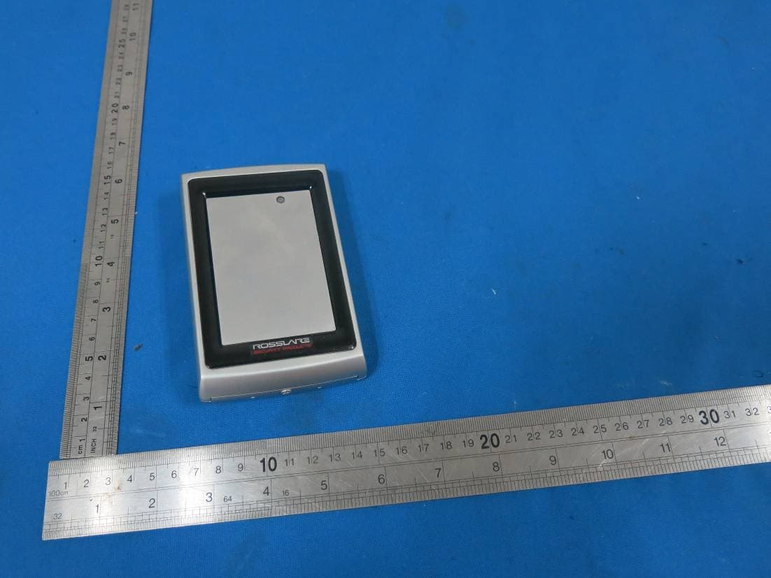
GCDAYQX0
Sep 20, 2015Reader
Equipment Class
DCD - Part 15 Low Power Transmitter Below 1705 kHz