GMLNPW-3Dual Band Tri-Mode Cellular Telephone
Microsoft Corporation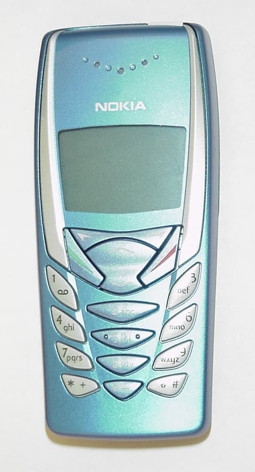
Click to zoom
Application Details
- Equipment Class
- TNE - Licensed Non-Broadcast Transmitter Held to Ear
- Date of Grant
- Mar 03, 2002
- Application Purpose
- Original Equipment
- Date of Application
- Dec 17, 2001
- Equipment Note
- Dual Band Tri-Mode Cellular Telephone
- Frequency Range
- 1850.04000000 - 1909.92000000
- Company
- Microsoft Corporation
- Country
- United States
Documents & Files
Document Text
Text extracted from the exhibit documents filed with the FCC. Open a document above to read the original.
Users Manual
Nokia 8265 User Guide Phone Notes NotesWhere to get information My numberWireless service provider Voice mail number Wireless service provider Wireless provider’s number Wireless service provider Provider’s customer care Wireless service provider Model number8265 Type label. Located under the battery inside the phone’s back cover. Phone typeNPW-3 Type label. Located under the battery inside the phone’s back cover. ESN (Electronic serial number) Type label. Located under the battery inside the phone’s back cover. 8265_1.BOOK Page i Friday, October 19, 2001 3:06 PM The wireless phone described in this guide is approved for use in TDMA and AMPS networks. Legal information Part No. 9353859, Issue 1 © 2001 Nokia Mobile Phones. All rights reserved. Nokia is a registered trademark of Nokia Corporation. Printed in Canada 11/2001 Nokia, Nokia Connecting People, and the Original Accessories logos are trademarks of Nokia Corporation and/or its affiliates. US Patent No 5818437 and other pending patents. T9 text input software Copyright © 1999-2001. Tegic Communications, Inc. All rights reserved. Includes RSA RSAFE cryptographic or security protocol software from RSA Security. The information contained in this user guide was written for Nokia phone 8265. The right to make changes and improvements to any of the products described in this guide without prior notice is reserved. Export Controls This product contains commodities, technology or software exported from the United States in accordance with the Export Administration regulations. Diversion contrary to U.S. law is prohibited. FCC/Industry Canada Notice Your phone may cause TV or radio interference (for example, when using a telephone in close proximity to receiving equipment). The FCC or Industry Canada can require you to stop using your telephone if such interference cannot be eliminated. If you require assistance, contact your local service facility. This device complies with part 15 of the FCC rules. Operation is subject to the condition that this device does not cause harmful interference. 8265_1.BOOK Page ii Friday, October 19, 2001 3:06 PM [ i ] Contents 1Safety first. . . . . . . . . . . . . . . . . . . . . . . . . . . . . . . . . . .1 2Welcome . . . . . . . . . . . . . . . . . . . . . . . . . . . . . . . . . . . .3 Get the most out of this guide. . . . . . . . . . . . . . . . . . .3 Understand wireless network services. . . . . . . . . . . . .5 Find information about your phone. . . . . . . . . . . . . . .6 Contact Nokia . . . . . . . . . . . . . . . . . . . . . . . . . . . . . . . .6 Contact your service provider . . . . . . . . . . . . . . . . . . .7 Learn about Accessibility solutions. . . . . . . . . . . . . . .8 3Phone setup. . . . . . . . . . . . . . . . . . . . . . . . . . . . . . . . .10 Install the battery. . . . . . . . . . . . . . . . . . . . . . . . . . . .10 Charge the battery . . . . . . . . . . . . . . . . . . . . . . . . . . .10 Remove the battery. . . . . . . . . . . . . . . . . . . . . . . . . . .11 4Phone basics . . . . . . . . . . . . . . . . . . . . . . . . . . . . . . . .12 Your Nokia 8265 phone . . . . . . . . . . . . . . . . . . . . . . .12 About the antenna . . . . . . . . . . . . . . . . . . . . . . . . . . .13 Learn the keys . . . . . . . . . . . . . . . . . . . . . . . . . . . . . . .13 Navigation keys. . . . . . . . . . . . . . . . . . . . . . . . . . . . . .15 icons and Indicators . . . . . . . . . . . . . . . . . . . . . . . . . .16 Review phone symbols . . . . . . . . . . . . . . . . . . . . . . . .17 5Phone calls. . . . . . . . . . . . . . . . . . . . . . . . . . . . . . . . . .19 6Phone menus. . . . . . . . . . . . . . . . . . . . . . . . . . . . . . . .22 Navigate menus. . . . . . . . . . . . . . . . . . . . . . . . . . . . . .22 Shortcuts . . . . . . . . . . . . . . . . . . . . . . . . . . . . . . . . . . .23 Phone book menu . . . . . . . . . . . . . . . . . . . . . . . . . . . .27 8265_1.BOOK Page i Friday, October 19, 2001 3:06 PM [ ii ] 7Letters and numbers entry. . . . . . . . . . . . . . . . . . . . .28 Enter letters . . . . . . . . . . . . . . . . . . . . . . . . . . . . . . . .28 Enter numbers. . . . . . . . . . . . . . . . . . . . . . . . . . . . . . .29 8Phone book. . . . . . . . . . . . . . . . . . . . . . . . . . . . . . . . . 31 About the phone book. . . . . . . . . . . . . . . . . . . . . . . . 31 Use phone book menus . . . . . . . . . . . . . . . . . . . . . . . 31 Add names and numbers. . . . . . . . . . . . . . . . . . . . . .33 Change a stored telephone number . . . . . . . . . . . . .33 Recall and redial numbers. . . . . . . . . . . . . . . . . . . . .34 Erase stored names and numbers . . . . . . . . . . . . . . .35 Erase the entire phone book . . . . . . . . . . . . . . . . . . .35 Check memory status. . . . . . . . . . . . . . . . . . . . . . . . .36 9Voice mail . . . . . . . . . . . . . . . . . . . . . . . . . . . . . . . . . .37 When you have a message . . . . . . . . . . . . . . . . . . . .37 Set up your voice mailbox. . . . . . . . . . . . . . . . . . . . .37 Set greetings and passwords. . . . . . . . . . . . . . . . . . .38 Listen to your voice messages. . . . . . . . . . . . . . . . . .38 10Call log . . . . . . . . . . . . . . . . . . . . . . . . . . . . . . . . . . . .39 Check the call log. . . . . . . . . . . . . . . . . . . . . . . . . . . .39 Check call timers . . . . . . . . . . . . . . . . . . . . . . . . . . . .42 11Advanced calling features. . . . . . . . . . . . . . . . . . . . .44 Set in-call options . . . . . . . . . . . . . . . . . . . . . . . . . . .44 Use call waiting . . . . . . . . . . . . . . . . . . . . . . . . . . . . .45 call forwarding. . . . . . . . . . . . . . . . . . . . . . . . . . . . . .47 Redial automatically . . . . . . . . . . . . . . . . . . . . . . . . .49 Use a calling card. . . . . . . . . . . . . . . . . . . . . . . . . . . .49 8265_1.BOOK Page ii Friday, October 19, 2001 3:06 PM [ iii ] Send your own number in caller ID. . . . . . . . . . .…
Text truncated - open the document above for the full version.
Users Manual
NOKIA 8265 (TDMA / AMPS)PRODUCT Wireless Telephone Kits and Accessories CODE ADAPTERS, CHARGERS and DESKTOP STANDS COMPACT DESKTOP CHARGING STANDDCH-8 SPARE BATTERY CHARGERDDC-1 STANDARD TRAVEL CHARGERACP-7U RAPID TRAVEL CHARGERACP-8U RAPID CIGARETTE LIGHTER CHARGER (780mA)LCH-9 BATTERIES EXTENDED 1000 mAh Li-Ion BATTERY BLB-3 CAR KITS EXPRESS CARKIT Includes Handsfree Rapid Cigarette Lighter Charger (PPH-1), Mobile Holder (MBD-11), Microphone (HFM-8), and Swivel Mount (HHS-15).CARK-141 CASES AND HOLDERS LEATHER CARRY CASE - WITH SHOULDER STRAPCSL-22 LEATHER CARRY CASECSL-23 MOBILE HOLDERMBD-11 . SOLID COLOR XPRESS-ON COVERS XPRESS-ON A&B COLOR COVERS - BLUE SKR-196 XPRESS-ON A&B COLOR COVERS - PURPLE SKR-197 XPRESS-ON A&B COLOR COVERS - PINK SKR-198 XPRESS-ON A&B COLOR COVERS - ORANGE SKR-199 KITS BOOM HEADSETHDB-5 HEADSET with Answer/End ButtonHDC-5 HEADSET HDE-2 LOOPSET Loopset (for use with T-Coil Equipped Hearing Aids) Includes loopset and 3 silver oxide batteriesLPS-3
Cover Letter(s)
2) Details of the procedures used to control the EUT and establish maximum power transmission during the tests. AMPS mode was tested with a build-in test mode, which makes it possible to activate transmitter to operate in maximum power level at desired channel. TDMA modes were activated through base- station simulator Rohde&Schwartz CMU200. Simulator was set to command EUT into maximum output power level on desired channels. 3) Physical description of the probe. Isotropic E-Field Probe ET3DV6 Construction Symmetrical design with triangular core Built-in optical fiber for surface detection system Built-in shielding against static charges PEEK enclosure material (resistant to organic solvents, e.g., glycolether) Calibration Calibration ceritifcate in Appendix C Frequency 10 MHz to 3 GHz (dosimetry); Linearity: ± 0.2 dB (30 MHz to 3 GHz) Optical Surface Detection ± 0.2 mm repeatability in air and clear liquids over diffuse reflecting surfaces Directivity ± 0.2 dB in HSL (rotation around probe axis) ± 0.4 dB in HSL (rotation normal to probe axis) Dynamic Range 5 μW/g to > 100 mW/g; Linearity: ± 0.2 dB Dimensions Overall length: 330 mm Tip length: 16 mm Body diameter: 12 mm Tip diameter: 6.8 mm Distance from probe tip to dipole centers: 2.7 mm Application General dosimetry up to 3 GHz Compliance tests of mobile phones Fast automatic scanning in arbitrary phantoms 4) Additional system verification information. Please discuss the source antenna, positioning. Also please provide manufacturer SAR verification plots. Two dipole antennas were used for system verification. These antennas are matched for use near flat phantoms filled with tissue simulating solution. They are manufactured by Schmid & Partner Engineering AG. Length of 835 MHz dipole antenna is 161mm with overall height of 330mm. Dipole length for 1900 MHz is 68 mm with overall height of 300mm. Both antennas were placed below the flat phantom with specific distance holders to ensure correct spacing between the phantom and the dipole. 5) Photographs of the liquid demonstrating a 15 cm depth, or z-axis scan plots at the highest SAR points. Z-axis scan at the highest SAR point in the body worn configuration. Z-axis scan at the highest SAR point in the Head configuration. 6) Photographs of the test setup and all test positions. Cheek position. Tilt position. 7) Justification of provided uncertainty calculation or an updated calculation. The FCC feels that a probe cal. contribution of 9.5% is more appropriate than the value of 3.6% shown in 6.1.1. Attached is updated uncertainty calculation. Given values are for k=1 conditions, and just combined extended uncertainty is made for k=2. Proposed 9.5% would be more closer to k=2 value. Uncertainty description Uncer t. value % Probabili ty distribut ion Div . c i 1 1g Stand . uncer t (1g) % v i 2 or v ef f Measurement System Probe calibration ±4.4 normal 1 1 ±4.4 ∞ Axial isotropy of the probe ±4.7 rectangul ar √3 (1- c p ) 1/2 ±1.9 ∞ Sph. Isotropy of the probe ±9.6 rectangul ar √3 (c p )1 / 2 ±3.9 ∞ Spatial resolution ±0.0 rectangul ar √3 1 ±0.0 ∞ Boundary effects ±5.5 rectangul ar √3 1 ±3.2 ∞ Probe linearity ±4.7 rectangul ar √3 1 ±2.7 ∞ Detection limit ±1.0 rectangul ar √3 1 ±0.6 ∞ Readout electronics ±1.0 normal 1 1 ±1.0 ∞ Response time ±0.8 rectangul ar √3 1 ±0.5 ∞ Integration time ±1.4 rectangul ar √3 1 ±0.8 ∞ RF ambient conditions ±3.0 rectangul ar √3 1 ±1.7 ∞ Mech. constrains of robot ±0.4 rectangul ar √3 1 ±0.2 ∞ Probe positioning ±2.9 rectangul ar √3 1 ±1.7 ∞ Extrap. and integration ±3.9 rectangul ar √3 1 ±2.3 ∞ Test Sample Related Device positioning ±6.0 normal 0.8 9 1 ±6.7 12 Device holder uncertainty ±5.0 normal 0.8 4 1 ±5.9 8 Power drift ±5.0 rectangul ar √3 1 ±2.9 ∞ Phantom and Setup Phantom uncertainty ±4.0 rectangul ar √3 1 ±2.3 ∞ Liquid conductivity (target) ±5.0 rectangul ar √3 0.6 ±1.7 ∞ Liquid ±10.0 rectangul √3 0.6 ±3.5 ∞ conductivity (meas.) ar Liquid permittivity (target) ±5.0 rectangul ar √3 0.6 ±1.7 ∞ Liquid permittivity (meas.) ±5.0 rectangul ar √3 0.6 ±1.7 ∞ Combined Standard Uncertainty ±13.6 Extended Standard Uncertainty (k=2) ±27.1
External Photos
G M L N P W - 3 G M L N P W - 3 G M L N P W - 3 G M L N P W - 3 G M L N P W - 3
ID Label/Location Info
The wireless phone described in this guide is approved for use in TDMA and AMPS networks. Legal information Part No. 9353859, Issue 1 © 2001 Nokia Mobile Phones. All rights reserved. Nokia is a registered trademark of Nokia Corporation. Printed in Canada 11/2001 Nokia, Nokia Connecting People, and the Original Accessories logos are trademarks of Nokia Corporation and/or its affiliates. US Patent No 5818437 and other pending patents. T9 text input software Copyright © 1999-2001. Tegic Communications, Inc. All rights reserved. Includes RSA RSAFE cryptographic or security protocol software from RSA Security. The information contained in this user guide was written for Nokia phone 8265. The right to make changes and improvements to any of the products described in this guide without prior notice is reserved. Export Controls This product contains commodities, technology or software exported from the United States in accordance with the Export Administration regulations. Diversion contrary to U.S. law is prohibited. FCC/Industry Canada Notice Your phone may cause TV or radio interference (for example, when using a telephone in close proximity to receiving equipment). The FCC or Industry Canada can require you to stop using your telephone if such interference cannot be eliminated. If you require assistance, contact your local service facility. This device complies with part 15 of the FCC rules. Operation is subject to the condition that this device does not cause harmful interference. 8265_1.BOOK Page ii Friday, October 19, 2001 3:06 PM MADE IN USA M o d e l : 8 2 6 5 T y p e : N P W - 3 ESN: 23500000000 Code: 0500000 MYDDFFL FCC ID: GMLNPW-3 CAN: 661331236A / 661281190A G M L N P W - 3
Internal Photos
GMLNPW-3 GMLNPW-3 GMLNPW-3 GMLNPW-3 GMLNPW-3
Internal Photos
GMLNPW-3
RF Exposure Info
[ 125 ] Reference information 20 If certain features are in use (Keyguard, fixed dialing, restrict calls, and so on), you might first need to turn those features off before you can make an emergency call. Consult this guide and your local cellular service provider. When making an emergency call, remember to give all of the necessary information as accurately as possible. Remember that your wireless phone might be the only means of communication at the scene of an accident—do not terminate the call until given permission to do so. •CERTIFICATION INFORMATION (SAR) THIS MODEL PHONE MEETS THE GOVERNMENT'S REQUIREMENTS FOR EXPOSURE TO RADIO WAVES. Your wireless phone is a radio transmitter and receiver. It is designed and manufactured not to exceed the emission limits for exposure to radio frequency (RF) energy set by the Federal Communications Commission of the U.S. Government. These limits are part of comprehensive guidelines and establish permitted levels of RF energy for the general population. The guidelines are based on standards that were developed by independent scientific organizations through periodic and thorough evaluation of scientific studies. The standards include a substantial safety margin designed to assure the safety of all persons, regardless of age and health. The exposure standard for wireless mobile phones employs a unit of measurement known as the Specific Absorption Rate, or SAR. The SAR limit set by the FCC is 1.6 W/kg.* Tests for SAR are conducted using standard operating positions accepted by the FCC with the phone transmitting at its highest certified power level in all tested frequency bands. Although the SAR is determined at the highest certified power level, the actual SAR level of the phone while operating can be well below the maximum value. This is because the phone is designed to operate at multiple power levels so as to use only the power required to reach the network. In general, the closer you are to a wireless base station antenna, the lower the power output. 8265_1.BOOK Page 125 Friday, October 19, 2001 3:06 PM [ 126 ] 20 Before a phone model is available for sale to the public, it must be tested and certified to the FCC that it does not exceed the limit established by the government-adopted requirement for safe exposure. The tests are performed in positions and locations (for example, at the ear and worn on the body) as required by the FCC for each model. The highest SAR value for this model phone as reported to the FCC when tested for use at the ear is ______ W/kg and when worn on the body, as described in this user guide, is _______ W/kg. (Body-worn measurements differ among phone models, depending upon available accessories and FCC requirements). While there may be differences between the SAR levels of various phones and at various positions, they all meet the government requirement. The FCC has granted an Equipment Authorization for this model phone with all reported SAR levels evaluated as in compliance with the FCC RF exposure guidelines. SAR information on this model phone is on file with the FCC and can be found under the Display Grant section of http://www.fcc.gov/oet/fccid after searching on FCC ID ______________. For body worn operation, to maintain compliance with FCC RF exposure guidelines, use only Nokia-approved accessories. When carrying the phone while it is on, use the specific Nokia belt-clip that has been tested for compliance. Use of non-Nokia-approved accessories may violate FCC RF exposure guidelines and should be avoided. *In the United States and Canada, the SAR limit for mobile phones used by the public is 1.6 watts/kilogram (W/kg) averaged over one gram of tissue. The standard incorporates a substantial margin of safety to give additional protection for the public and to account for any variations in measurements. SAR values may vary depending on national reporting requirements and the network band. For SAR information in other regions please look under product information at http://www.nokia.com. 8265_1.BOOK Page 126 Friday, October 19, 2001 3:06 PM PC Site Oulu Exhibit 11: SAR Report DTX03527-EN Applicant: Nokia Oyj FCC ID: GMLNPW-3 Copyright 2001 Nokia Oyj 1 (14) SAR Compliance Test Report Test report no.: Not numbered Date of report: 2001-12-8 Number of pages: 49 Contact person: Olli Kautio Responsible test engineer: Pertti Mäkikyrö Testing laboratory: Nokia Oyj Elektroniikkatie 10 P.O. Box 50 FIN-90571 OULU Finland Tel. +358-10-5051 Fax. +358-10-505 7222 Client: Nokia Inc. 6000 Connection Dr. Mailstop 2:200 Irving Tx, 75039 USA Tel. +1 972 894 5000 Fax. +1 972 894 4589 Tested devices: GMLNPW-3 CSL-22, CSL-23 Supplement reports: - Testing has been carried out in accordance with: IEEE P1528-200X Draft 6.4 Recommended Practice for Determining the Peak Spatial-Average Specific Absorption Rate (SAR) in the Human Body Due to Wireless Communications Devices: Experimental Techniques Documentation: The documentation of the testing performed on the tested devices is archived for 15 years at PC Site Oulu Test results: The tested device complies with the requirements in respect of all parameters subject to the test. The test results and statements relate only to the items tested. The test report shall not be reproduced except in full, without written approval of the laboratory. Date and signatures: 2001-12-11 For the contents: Pertti Mäkikyrö Engineering Manager, EMC Miia Nurkkala Test Engineer PC Site Oulu Exhibit 11: SAR Report DTX03527-EN Applicant: Nokia Oyj FCC ID: GMLNPW-3 Copyright 2001 Nokia Oyj 2 (14) CONTENTS 1.SUMMARY FOR SAR TEST REPORT ..........................................................................................................................3 1.1 MAXIMUM RESULTS FOUND DURING SAR EVALUATION.................................................................................................................. 3 1.1.1Head Configuration...........................................................................…
Text truncated - open the document above for the full version.
RF Exposure Info
SAR A) Regarding your answer to question 1. Please provide the impedance of each headset/loopset accessory, a statement regarding any metal content in the colored covers mentioned, and a photograph of the MBD-11 mobile holder. Also, please justify why tests with the MBD-11 were not made. Provide additional data as appropriate. MBD-11 is a car-kit accessory, not a body worn accessory. Therefore, SAR results are not required. See drawing and attached photo. 1. MBD-11 • Passive holder supports use with mobile charger and Plug-in HF Car Kit Impedance information: HDE-2HDC-5HDB-5LPS-3 Microphone 2.2 kOhm at 1 kHz2.2 kOhm at 1 kHz 2.2 kOhm at 1 kHz 2.2 kOhm at 1 kHz Speaker 150 Ohm at 1 kHz150 Ohm at 1 kHz 150 Ohm at 1 kHz 330 Ohm at 1 kHz None of the covers available for this product include metallic content. B) Justification of the differing probe calibration factors noted between the manufacturer verification data and the verification done on site. Please discuss the expected variation on the verification results. Schmid and Partner Engineering AG uses their own E-field probe for measuring the verification data whereas Nokia's SAR laboratory uses their own probe for system verification. These E- field probes are handmade and each is an individual. This explains the differences between the calibration factors. Conductivity measurements, source power settings and laboratory setup can be expected to cause variation on the verification results. Uncertainty calculation for system verification is attached.
RF Exposure Info
Schmid & Partner Engineering AG Uncertainty System Check (Dipole Validation) – IEEE P1528 Error Description Uncertainty value ±% Probability distribution divisorc i 1 1g Standard unc. (1g) v i 2 or v eff Measurement System Probe calibration± 4.4normal11± 4.4%∞ Axial isotropy of the probe± 4.7rectangular√3 (1-c p ) 1/2 ± 2.7%∞ Sph. isotropy of the probe± 9.6rectangular√3 (c p ) 1/2 ± 0%∞ Boundary effects± 5.5rectangular√31± 3.2%∞ Probe linearity± 4.7rectangular√31± 2.7 %∞ Detection limit± 1.0rectangular√31± 0.6 %∞ Readout electronics± 1.0normal11± 1.0 %∞ Response time± 0.0rectangular√31± 0.0 %∞ Integration time± 0.0rectangular√31± 0.0%∞ RF ambient conditions± 3.0rectangular√31± 1.7 %∞ Mech. constrains of robot± 0.4rectangular√31± 0.2 %∞ Probe positioning± 2.9rectangular√31± 1.7 %∞ Extrap. and integration± 3.9rectangular√31± 2.3 %∞ Test Sample Related Distance dipole-liquid± 1.0rectangular√31± 0.6 %∞ Input power± 4.7rectangular√31± 2.7%∞ Phantom and Setup Phantom uncertainty± 4.0rectangular√31± 2.3 %∞ Liquid conductivity (target)± 5.0rectangular√30.6± 1.7 %∞ Liquid conductivity (meas.)± 10.0rectangular√30.6± 3.5 %∞ Liquid permittivity (target)± 5.0rectangular√30.6± 1.7 %∞ Liquid permittivity (meas.)± 5.0rectangular√30.6± 1.7 %∞ Combined Standard Uncertainty± 9.5% Extended Standard Uncertainty (k=2)± 19.0 %
Test Report
TCC Company Confidential 2 ( 85) FCC ID: GMLNPW-3 Test & Certification Center (TCC) - DallasTest Report #: 01-RF-0626 December 12, 2001Ver 1.0 CFR 47 Part 2, 22, and 24 Test Report© 2001 Nokia Mobile Phones TABLE OF CONTENTS 1.GENERAL.................................................................................................................................................................. 4 1.1QUALITY SYSTEM.................................................................................................................................................. 4 1.2LIST OF GENERAL INFORMATION REQUIRED FOR CERTIFICATION............................................................................. 4 1.3OBJECTIVE........................................................................................................................................................... 6 1.4TEST SUMMARY.................................................................................................................................................... 6 2.STANDARDS BASIS................................................................................................................................................. 7 3.LIST OF ABBREVIATIONS, ACRONYMS AND TERMS......................................................................................... 8 3.1ABBREVIATIONS.................................................................................................................................................... 8 3.2ACRONYMS........................................................................................................................................................... 8 3.3TERMS................................................................................................................................................................. 8 4.EQUIPMENT-UNDER-TEST (EUT)........................................................................................................................... 9 4.1DESCRIPTION OF TESTED DEVICE(S):..................................................................................................................... 9 4.2PHOTOGRAPH OF TESTED DEVICE(S):.................................................................................................................... 9 5.TEST EQUIPMENT LIST......................................................................................................................................... 10 6.RF POWER OUTPUT (CONDUCTED).................................................................................................................... 11 6.1SETUP................................................................................................................................................................ 11 6.2PASS/FAIL CRITERIA........................................................................................................................................... 11 6.3DETAILED TEST RESULTS.................................................................................................................................... 11 7.RF POWER OUTPUT (RADIATED)........................................................................................................................ 12 7.1SETUP................................................................................................................................................................ 12 7.2PASS/FAIL CRITERIA........................................................................................................................................... 13 7.3DETAILED TEST RESULTS.................................................................................................................................... 13 7.4MEASUREMENT UNCERTAINTY............................................................................................................................. 15 8.TX AUDIO FREQUENCY RESPONSE.................................................................................................................... 16 8.1SETUP................................................................................................................................................................ 16 8.2PASS/FAIL CRITERIA........................................................................................................................................... 16 8.3DETAILED TEST RESULTS.................................................................................................................................... 17 9.MODULATION LIMITING........................................................................................................................................ 19 9.1SETUP................................................................................................................................................................ 19 9.2PASS/FAIL CRITERIA........................................................................................................................................... 19 9.3DETAILED TEST RESULTS.................................................................................................................................... 20 10.MODULATION REQUIREMENTS (MEASUREMENT OF MAXIMUM DEVIATION).......................................... 22 10.1SETUP................................................................................................................................................................ 22 10.2PASS/FAIL CRITERIA........................................................................................................................................... 22 10.3DETAILED TEST RESULTS.................................................................................................................................... 23 11.OCCUPIED BANDWIDTH (EMISSIONS MASKS).............................................................................................. 24 11.1SETUP............................…
Text truncated - open the document above for the full version.
Test Report
TCC Company Confidential 2 ( 46) FCC ID: GMLNPW-3 Test & Certification Center (TCC) - DallasTest Report #: 01-RF-0626 Amendment A February 13, 2002Ver 1.0 CFR 47 Part 2, 22, and 24 Test Report© 2002 Nokia Mobile Phones TABLE OF CONTENTS 1.GENERAL.................................................................................................................................................................. 3 1.1 Q UALITY SYSTEM..................................................................................................................................................... 3 1.2 O BJECTIVE............................................................................................................................................................... 3 11.OCCUPIED BANDWIDTH (EMISSIONS MASKS) ............................................................................................... 5 11.1S ETUP................................................................................................................................................................. 5 11.2P ASS/FAIL CRITERIA............................................................................................................................................. 6 11.3D ETAILED TEST RESULTS..................................................................................................................................... 6 11.4M EASUREMENT UNCERTAINTY............................................................................................................................ 21 12.OCCUPIED BANDWIDTH (TRANSMITTER CONDUCTED MEASUREMENTS) ............................................. 22 12.1S ETUP............................................................................................................................................................... 22 12.2P ASS/FAIL CRITERIA........................................................................................................................................... 22 12.3D ETAILED TEST RESULTS................................................................................................................................... 23 12.4M EASUREMENT UNCERTAINTY........…
Text truncated - open the document above for the full version.
Contact Information
Applicant
Hasnain Syed(Director, EMC, SI and RF Compliance)
Technical Contact
Nokia Mobile Phones, Inc.Randy Leenerts
[email protected]972-894-5000
6000 Connection Drive · Irving, Texas · United States
Non-Technical Contact
Nokia Mobile Phones, Inc.Alan C Ewing
[email protected]972-894-5000
Test Firm
Nokia Mobile PhonesRandy Leenerts
Technical Specifications
| # | Rule Parts | Frequency Range | Power Output | Emission | Tolerance |
|---|---|---|---|---|---|
| 4 | 24E | 1.85 GHz - 1.91 GHz | 1.679 W | 30K0DXW | 0.02 ppm |
Other Applications from Microsoft Corporation

GMLRM-88A
Apr 11, 2006GSM 850/900/1800/1900MHz Cellphone w/BT
Equipment Class
JBP - Part 15 Class B Computing Device Peripheral
GMLRM-88
Jan 19, 2006GSM 850/900/1800/1900MHz Cellphone w/BT
Equipment Class
DSS - Part 15 Spread Spectrum Transmitter
GMLNPM-10X
Oct 29, 2003Dual Band Mobile Phone
Equipment Class
PCE - PCS Licensed Transmitter held to ear
GMLRH-25
Sep 10, 2003Tri mode Dual Band Cellular Phone
Equipment Class
PCE - PCS Licensed Transmitter held to ear
GMLRH-42
Aug 27, 2003Nokia 2220 single band cellphone
Equipment Class
TNE - Licensed Non-Broadcast Transmitter Held to Ear