GSS-MW251V110802.11/b Wireless Monitor-Airpanel V110
ViewSonic Corporation
Click to zoom
Application Details
- Equipment Class
- DTS - Digital Transmission System
- Date of Grant
- Apr 23, 2003
- Application Purpose
- Original Equipment
- Date of Application
- Apr 23, 2003
- Equipment Note
- 802.11/b Wireless Monitor-Airpanel V110
- Frequency Range
- 2412.00000000 - 2462.00000000
- Company
- ViewSonic Corporation
- Country
- United States
Documents & Files
Document Text
Text extracted from the exhibit documents filed with the FCC. Open a document above to read the original.
Users Manual
ViewSonic ® User Guide Guide de l’utilisateur Bedienungsanleitung Wireless Monitor V110 2 ViewSonic airpanel V110 8-30-02 ViewSonic airpanel V110 i Contents Introduction Your airpanel V110 Wireless Monitor ..................................... 2 Precautions ............................................................................ 2 airpanel V110 Features .......................................................... 3 Front Control Buttons and Features ................................... 3 Rear Connection Ports & Panels ....................................... 4 Battery & Power Properties .................................................... 5 Battery Power Status .......................................................... 5 Changing the Battery ....................................................... 6 Antenna Signal Properties ...................................................... 6 Wireless Connection Signal Status ..................................... 6 Basic Setup Charging the Battery .............................................................. 7 Using the AC/DC Power Converter ..................................... 7 Setting Up Software ............................................................... 8 BEFORE YOU BEGIN ........................................................ 8 Accessing Information from your Home PC ........................ 12 Using the airpanel V110 The Buttons ............................................................................ 13 Using the Stylus ..................................................................... 14 Moving Windows ................................................................. 14 Operating System not Responding ..................................... 15 Calibrating the Touch Screen .............................................. 15 Adjusting Stylus Double-tap Rate ....................................... 15 Resetting your airpanel .......................................................... 16 Soft Reset ........................................................................... 16 Hard Reset .......................................................................... 16 PCMCIA Cards ....................................................................... 17 Using a PCMCIA Card ....................................................... 17 airpanel Settings ..................................................................... 18 Device Settings ................................................................... 18 Optional Accessories The ViewSonic airpanel V110 Dock ....................................... 24 Commercially Available Options ............................................. 25 ii ViewSonic airpanel V110 External USB Keyboard ...................................................... 25 External USB Mouse ........................................................... 25 External Headphone Set ..................................................... 25 External Microphone ........................................................... 25 Appendix airpanel V110 Specifications .................................................. 26 Customer Support .................................................................. 28 Cleaning and Maintenance .................................................... 29 Limited Warranty .................................................................... 30 Safety Guidelines ................................................................... 31 Compliance and Safety Notices ............................................. 32 Radio Frequency Interference (RFI) Compliance ............... 32 Safety Notices ..................................................................... 34 ViewSonic airpanel V110 1 airpanel V110 Copyright © ViewSonic Corporation, 2002. All rights reserved. airpanel is a trademark of ViewSonic Corporation. ViewSonic, and the three birds logo are registered trademarks of ViewSonic Corporation. Microsoft, Windows, Windows CE, Windows CE Inbox, Explorer and Internet Explorer, Pocket Word, Microsoft Word, Active Sync, MSN, Excel, Windows RDP and the Windows logo are trademarks of Microsoft Corporation in the United States and other countries. Citrix, WindView, and ICA are registered trademarks of Citrix Systems, Inc. MetaFrame is a trademark of Citrix Systems, Inc. Intel and X-Scale are registered trademarks of Intel Corporation. VESA is a registered trademark of the Video Electronics Standards Association. CompactFlash is a trademark of the CompactFlash Association. E NERGY S TAR ® is a registered trademark of the U.S. Environmental Protection Agency (EPA). As an E NERGY S TAR ® partner, ViewSonic Corporation has determined that this product meets the E NERGY S TAR ® guidelines for energy efficiency. Disclaimer: ViewSonic Corporation shall not be liable for technical or editorial errors or omissions contained herein; nor for incidental or consequential damages resulting from furnishing this material, or the performance or use of this product. In the interest of continuing product improvement, ViewSonic Corporation reserves the right to change product specifications without notice. Information in this document may change without notice. No part of this document may be copied, reproduced, or transmitted by any means, for any purpose without prior written permission from ViewSonic Corporation. Product Registration To meet your future needs, and to receive any additional product information as it becomes available, please register your product on the Internet at: www.viewsonic.com. The airpanel V110 Utility CD-ROM also provides an opportunity for you to print the registration form, which you may mail or fax to ViewSonic. Product disposal at end of product life ViewSonic is concerned about the preservation of our environment. Please dispose of this product properly at the end of its useful life. Your local waste disposal company may provide information about proper disposal. For Your Records Product Name: Model Number: Documen…
Text truncated - open the document above for the full version.
Users Manual
18 ViewSonic airpanel V110 air panel Settings User guides and instructions for the Microsoft Windows for Smart Display software and Windows CE. Net are included on the airpanel V110 Utility CD-ROM. Device Settings The airpanel V110 desktop provides these useful features: • A Battery Charge Status Icon • A Network Selection Option • A Help Button • A Settings Button Tapping the Settings button opens the Settings window which features tabs for establishing device settings in these functional areas: • General Settings • Wireless Network Settings • Advanced Settings • Power Settings • System Info Settings ViewSonic airpanel V110 19 General Settings Figure 13: The General Settings Panel Allows you to alter and control the operator usage environment: • Sound - Sets sound volume to Loud, Soft, or Off for the airpanel. Allows the home PC to send sound to the airpanel, keep sound on the home PC, or to mute sound on the home PC. • Stylus - Sets the stylus’ Double-tap rate and allows you to calibrate the alignment of stylus taps to the screen. This later feature can be useful when the screen fails to respond accurately to the stylus. • New Connection - For advanced users only. Allows you to create a new network connection. • Wallpaper - Toggles the computer’s wallpaper On/Off. (Wallpaper On can slow performance.) Adding a New User to a Home PC Yo u r airpanel Wireless Monitor can have more than one user with access linked to your Home PC. For instance, you and your spouce can have individual links to your Home PC. Each added user link will have its own login icon on the desktop and its own individual password. The preferred way to add a new user to the airpanel Wireless Monitor is by running the Microsoft Mira CD on the Home PC then following the simple directions. The help files for Microsoft Windows XP are also an excellent background resource. For the advanced user, to add a new user from the General settings panel: 1 Click the New button under New Connection 2 Enter the User Name and Computer Name in the New Connection window 3 Select a password option 4 Select a launch option under Default Connection, then click OK. 20 ViewSonic airpanel V110 Wireless Network Settings Figure 14: The Wireless Network Settings Panel Allows the user to alter and control connections to another device: • Available Networks - Lists all networks available to the airpanel allowing you to choose a connection. • Preferred Networks - Allows you to automatically connect to a network from a list of preferred networks. Adding a New Home PC Your airpanel Wireless Monitor can have links to more than one Home PC. For instance, the airpanel can be linked to a your personal Home PC when you are at home and to your work Home PC when you are in the office. Each additional Home PC link will have its own connection title in the Wireless Network settings panel for you to choose from. The preferred way to add a new Home PC to the airpanel Wireless Monitor is by running the Microsoft CD on the Home PC then following the simple directions. The help files for Microsoft Windows XP are also an excellent background resource. For the advanced user, to add an available peer-to-peer Home PC from the Wireless Networks panel: 1 Select the Home PC to be added from the list under Available Networks 2 Tap Configure to give a name to the new connection, then click OK. 3 Assign a default priority to the new connection under Preferred Networks then click OK. ViewSonic airpanel V110 21 The Advanced Button’s Wireless Network Settings Terminology The Advanced button allows the user to set these Networks to Access connection options: • Computer-to-Computer (Ad Hoc) Networks Only - this means limiting access to PCs with their own built-in wireless cards or attached external wireless adapters. This is also referred to as a peer-to-peer type connection. • Access Point (Infrastructure) Networks Only - this means limiting access to networks with a wireless adapter attached to the network rather than attached to a particular PC. After selecting such a network, you will need to specify a particular PC on the network to complete the connection. • Any Available Network (Acces Point Preferred) - this means access is not limited to a particular type of wireless network. NOTE: If you are not thoroughly familiar with network types, you should avoid making changes to the Advanced settings without first seeking assistance from the Microsoft Windows XP Help Files Advanced Settings Figure 15: The Advanced Settings Panel Allows the advanced user to control advanced settings. The options available on the Advanced tab should be attempted only by an advanced user and should be avoided by the novice. The advanced features include: • IP Settings - Allows the user to chose between an automatically set IP address (DHCP) or a specified IP (user filled-in) address. 22 ViewSonic airpanel V110 • DNS Settings - Allows the user to write in a specific server address for assignment to a particular server. NOTE: If you are not thoroughly familiar with IP and DNS settings, you should avoid making changes to the Advanced settings without first seeking assistance from the Microsoft Windows XP Help Files. Power Settings Figure 16: The Power Settings Panel • Battery Power - Allows you to set the time you want the airpanel to wait before entering Standby mode and Shutdown mode in order to save battery power. • AC Power - Allows you to set the time you want the airpanel to wait before entering Standby mode and Shutdown mode in order to save AC power. (Useful in conjunction with Uninterruptable Power Supplies or to prolong the life of the device.) ViewSonic airpanel V110 23 System Info Settings Figure 17: The System Information Panel These settings can be useful for analytical purposes or for when dealing with customer service: • Device - Allows the user to review (but not alter) the device settings for device name, copyright, firmware version, installed OS version, and build. • Network - Allows …
Text truncated - open the document above for the full version.
Block Diagram
SMI 712 PCI P.17 System Power Management Buffers LCD P.19 P.9 P.13,14 P.21~24 FF Serial P.17 AC97 Data/Address Bus USB Device x1 Debug message output P.17 RS232 & JTAG P.6 TWV1500 &TWV1040 SYSTEM BLOCK P.10 Mic IT8152 Buffers P.19 CRADLE CONNECTOR CPLD-32 4-Wire Touch Screen (For 10.4") PCMCIA Control I/F Flash Chip Select Control CRT P.7~8 Mini PCI x1 USB Host B Ear Phone P.18 SDRAM P.11 Bottom Board Connector P.11 P.16 Audio Codec WM9705 USB A/B P.20 P.5 CPU Cotulla USB Host A Flash Memory P.3 & P.4 P.15 P.25 PCMCIA-SOCKET 6-wire Touch Screen (for 15")
Cover Letter(s)
ViewSonic Corporation Mar. 14, 2003 Federal Communications Commission Authorization and Evaluation Division FCC ID: GSS-MW251V110 Confidentiality Request Pursuant to Sections 0.457 and 0.459 of the Commission’s Rules, the Applicant hereby requests confidential treatment of information accompanying this Application as outlined below: 1. Schematics 2. Operational Description The above materials contain trade secrets and proprietary information not customarily released to the public. The public disclosure of these matters might be harmful to the Applicant and provide unjustified benefits to its competitors. The Applicant understands that pursuant to Rule 0.457, disclosure of this Application and all accompanying documentation will not be made before the date of the Grant for this application. . Sincerely, James Huang, 3/14/03 Regulatory Compliance Manager Advanced Technology Group ViewSonic Corporation Office: 909-444-8786 Mobile: 909-532-5119 Fax: 909-468-1244 E-Mail: [email protected] 381 Brea Canyon Road, Walnut, California 91789 (909) 869-7976 * Fax (909) 468-3756 http://www.viewsonic.com
Cover Letter(s)
MessageFrom: Eva Kao [[email protected]] Sent: Wednesday, April 23, 2003 12:17 AM To: Mike Kuo; 'Vincent' Cc: ? ??; ? ??; Scott Wang Subject: Re: ViewSonic Corp., FCC ID:GSS-MW251V110, AN03T2711 Hi Mike, Answer #5: We got the wrong internal photos, please find the attached is revised internal photos Answer #9: The EMC test was performed and finished on November 11, 2002. so the modification are implemented on the SAR device. Best Regards, Vincent ----- Original Message ----- From: Mike Kuo To: 'Vincent' ; Mike Kuo Cc: ? ?? ; ? ?? ; ? ?? ; Scott Wang Sent: Wednesday, April 23, 2003 2:20 PM Subject: RE: ViewSonic Corp., FCC ID:GSS-MW251V110, AN03T2711 Hi Vincent: Please get back to me on Question #5 and #9. When questions are issued, I need to have your reply in writing. Best Regards Mike Kuo Compliance Certification Services 561F Monterey Road Morgan Hill, CA 95037 Tel: (408)463-0885 x:105 Fax:(408)463-0888 e-mail:[email protected] -----Original Message----- From: Vincent [mailto:[email protected]] Sent: Tuesday, April 22, 2003 11:20 PM To: MIKE Cc: ? ??; ? ??; ? ??; ScottWang Subject: Fw: ViewSonic Corp., FCC ID:GSS-MW251V110, AN03T2711 Hi Mike Is there any other problem for ViewSonic's project, FCC ID: GSS- MW251V110/AN03T2711(SAR #24468) ? Due to this project is on top urgent, can you Grant it first. Thanks Vicnent ----- Original Message ----- From: Eva Kao To: Mike Kuo ; Vincent Sent: Monday, April 21, 2003 11:34 AM Subject: Re: ViewSonic Corp., FCC ID:GSS-MW251V110, AN03T2711 Hi Mike, Attached please find the revised internal photos. Thank you! Eva -----Original Message----- From: Mike Kuo [mailto:[email protected]] Sent: Wednesday, April 16, 2003 1:47 AM To: 'Eva Kao'; 'Lucy_Tsai (E-mail); Vincent Su; Helen Zhao; Mike Kuo Subject: RE: ViewSonic Corp., FCC ID:GSS-MW251V110, AN03T2711 Hi Eva: When there are some questions not addressed in your reply, please let me know what action will be taken. You did not address Question #5 and #9. Please let me know how are you going to address these two questions. Best Regards Mike Kuo -----Original Message----- From: Eva Kao [mailto:[email protected]] Sent: Tuesday, April 15, 2003 1:59 AM To: 'Lucy_Tsai (E-mail); Vincent Su; Helen Zhao; Mike Kuo Subject: Fw: ViewSonic Corp., FCC ID:GSS-MW251V110, AN03T2711 Notice_content ------------- Question #1: Last two pictures of internal photos with label " Antenna module and antenna-B " and Antenna module with antenna-F". Are there two types of antennas included in this filing ? Or you are saying Antenna front side and Antenna Back side ? Please explain. Ans.: Just one type of antenna including in this file. It's antenna front side and back side view. Question #2: In the operational description file, it states "Under normal use condition, the user has to keep at least 20 cm separation distance between radiator and the body of the user. The other instruction, please have a look at the users manual." Ans.: Revised operational description is attached. Since this device can also be used as panel PC which the end user can not maintain 20cm separation distance but do consider such position is normal operating conditions. Please remove or revise this statement in the operational description. Question #3: The antenna specification file provided looks like dipole antenna but the antenna in the internal photos looks like PCB antenna. Please explain the difference. Ans.: The antenna type is PCB antenna, In the antenna spec. page 2, The symbol " 1 in circle" indicates antenna connector length. The symbol " 2 in circle" indicates antenna cable length. The symbol " 3 in circle" indicates PCB antenna Question #4: In the SAR test report, the antenna gain is 3dBi but in the EMC test report, the antenna gain is listed as 0dBi. Please explain the difference. The Antenna gain shall be 0 dBi , Please modify SAR report. Question #5: The antenna shown in the SAR test report does not agree the antenna shown in the internal photos. Please explain. Question #6: In the user manual, there is optional extended battery pack offered with this device. In the SAR test report, only one battery was tested. Please provide additional SAR test data with extended battery. We delete extended battery pack in the user manual. Please find revised user manual. Question #7:In the user manual, the wireless function is achieved via external USB adaptor. On the other hand, the wireless device included in this application is Mini-PCI type Wireless module installed inside the device by the manufacturer, please provide revised user manual to harmonize the wireless function to match with the device under tests. Please find revised user manual. Question #8: There is no RF exposure warning statement provided in the user manual. Please provide revised user manual. Please find revised user manual. Question #9 As demonstrated in the internal photos, modifications were made during final compliance tests. Since the SAR tests were tested before the EMC tests by comparing the test dates, the modifications made on the EUT during the EMC tests may have effects on the SAR test report tested before EMC tests. Please verify that the EUT tested during the SAR evaluation is representative device to the one tested during EMC tests. If the modifications are not implemented on the SAR device, SAR tests may be to evaluate again. Question #10: Please provide modification report signed by the applicant to agree that all modifications made the device will be incorporated into each unit sold in the U.S. Please find the modification report. Best Regards Mike Kuo The items indicated above must be submitted before processing can continue on the above referenced application. Failure to provide the requested information within 60 days of the original e-mail date may result in application dismissal and forfeiture of the filing fee. Also, please note that partial responses increase processing time and should not be submitted. Any questions about the content of this correspondence should…
Text truncated - open the document above for the full version.
Cover Letter(s)
APPENDIX 3 PHOTOGRPHS OF MODIFICATION Modify Description 1. One cooper sheet provides at base holder, see photo for details. 2. Emission isolation tape provides at signal cables, see photos for details. View of base holder View of Panel cooper sheet Emission isolation tape Emission isolation tape
External Photos
C&C Laboratory Co. Ltd. REPORT NO: 030030-RF-ID ID: GSS-MW251V110 DATE: March 07 2003 Page 47 Rev. 00 APPENDIX 2 EXTERNAL PHOTOGRPHS OF EUT C&C Laboratory Co. Ltd. REPORT NO: 030030-RF-ID ID: GSS-MW251V110 DATE: March 07 2003 Page 48 Rev. 00 Front View of EUT Left View of EUT C&C Laboratory Co. Ltd. REPORT NO: 030030-RF-ID ID: GSS-MW251V110 DATE: March 07 2003 Page 49 Rev. 00 Right View of EUT Back View of EUT C&C Laboratory Co. Ltd. REPORT NO: 030030-RF-ID ID: GSS-MW251V110 DATE: March 07 2003 Page 50 Rev. 00 Front of Adaptor Back of Adaptor
ID Label/Location Info
FCC ID LABEL FORMAT AND LOCATION Applicant: ViewSonic Corp. FCC ID: GSS-MW251V110 FCC ID: GSS-MW251V110 This device complies with part 15 of the FCC Rules. Operation is subject to the following two conditions: (1) This device may not cause harmful interference, and (2) this device must accept any interference received, including interference that may cause undesired operation. FCC ID LABEL AREA
Internal Photos
C&C Laboratory Co. Ltd. REPORT NO: 030030-RF-ID ID: GSS-MW251V110 DATE: March 07 2003 Page 51 Rev. 01 APPENDIX 3 INTERNAL PHOTOGRPHS OF EUT C&C Laboratory Co. Ltd. REPORT NO: 030030-RF-ID ID: GSS-MW251V110 DATE: March 07 2003 Page 52 Rev. 01 Inside View of EUT-1 Inside View of EUT-2 C&C Laboratory Co. Ltd. REPORT NO: 030030-RF-ID ID: GSS-MW251V110 DATE: March 07 2003 Page 53 Rev. 01 Inside View of EUT-4 Inside View of EUT-5 C&C Laboratory Co. Ltd. REPORT NO: 030030-RF-ID ID: GSS-MW251V110 DATE: March 07 2003 Page 54 Rev. 01 Inside View of EUT-6 Inside View of EUT-7 C&C Laboratory Co. Ltd. REPORT NO: 030030-RF-ID ID: GSS-MW251V110 DATE: March 07 2003 Page 55 Rev. 01 Inside View of EUT-8 Inside View of EUT-9 C&C Laboratory Co. Ltd. REPORT NO: 030030-RF-ID ID: GSS-MW251V110 DATE: March 07 2003 Page 56 Rev. 01 Front of Module And Antenna-F Front of Module And Antenna-B
Parts List/Tune Up Info
Mira 10.4” Mira15” 4-Band 2 2 . 4 4 G G G H H H z z z ~ ~ ~ 2 2 2 . . 5 5 5 G G G H H H z z 2 . . 4 . z 5 5 . 1 1 5 5 G G G H H H z z z ~ ~ ~ 5 5 5 . . 2 2 2 5 5 5 G G G H H H z z 5 . . 1 5 . z 5 5 . 2 2 5 5 G G G H H H z z z ~ ~ ~ 5 5 5 . . 3 3 3 5 5 5 G G G H H H z z 5 . . 2 5 . z 5 5 . 7 7 2 2 5 5 G G G H H H z z z ~ ~ ~ 5 5 5 . . 8 8 8 5 5 5 G G G H H H z z 5 . . 7 2 5 . z
RF Exposure Info
in accordance with the requirements of FCC Report and Order: ET Docket 93-62, and OET Bulletin 65 Supplement C for Wireless Monitor With 802.11b Wireless Mini-PCI Card Model: VSMW24668-1W, -1M, -1E, -1J, -1G FCC ID: GSS-MW251V110 January 3, 2003 REPORT NO: 02T1748-1 Prepared for ViewSonic Corp. 381 Brea Canyon Road Walnut, CA 91789, USA Prepared by COMPLIANCE CERTIFICATION SERVICES 561F MONTEREY ROAD, MORGAN HILL, CA 95037 USA TEL: (408) 463-0885 REPORT NO: 02T1748-1 DATE: January 3, 2003 FCC ID: GSS-MW251V110 COMPLIANCE CERTIFICATION SERVICES Page: 2 of 23 This report shall not be reproduced except in full, without the written approval of CCS. This document may be altered or revised by Compliance Certification Services personnel only, and shall be noted in the revision section of the document. CERTIFICATE OF COMPLIANCE (SAR EVALUATION) Dates of Tests: January 3, 2003 Report No: 02T1748-1 APPLICANT: ViewSonic Corp. 381 Brea Canyon Road Walnut, CA 91789, USA MODEL: VSMW24668-1W, -1M, -1E, -1J, -1G FCC ID: GSS-MW251V110 DEVICE CATEGORY: PORTABLE DEVICES EXPOSURE CATEGORY: GENERAL POPULATION/UNCONTROLLED EXPOSURE Test Sample is a: Production unit Modulation type: Direct Sequence Spread Spectrum Operating mode: Maximum continuous output Tx Frequency: 2412 ~ 2462 MHz Max. O/P Power (Conducted): 14.80 dBm (2412 MHz) Max. SAR (1g): 0.467 mW/g (2412 MHz) Application type: Certification FCC Rule part(s): § 15.247 Wireless module: Manufactured: Bromax, P/N: 577320003 This wireless portable device has been shown to be capable of compliance for localized specific absorption rate (SAR) for uncontrolled environment/general population exposure limits specified in ANSI/IEEE Std. C95.1-1992 and had been tested in accordance with the measurement procedures specified in FCC OET 65 Supplement C (released on 6/29/2001 see Test Report). I attest to the accuracy of data. All measurements reported herein were performed by me or were made under my supervision and are correct to the best of my knowledge and belief. I assume full responsibility for the completeness of these measurements and vouch for the qualifications of all persons taking them. Steve Cheng EMC Engineering Manager REPORT NO: 02T1748-1 DATE: January 3, 2003 FCC ID: GSS-MW251V110 COMPLIANCE CERTIFICATION SERVICES Page: 3 of 23 This report shall not be reproduced except in full, without the written approval of CCS. This document may be altered or revised by Compliance Certification Services personnel only, and shall be noted in the revision section of the document. TABLE OF CONTENT 1. EUT DESCRIPTION........................................................................................................4 2. REQUIREMENTS FOR COMPLIANCE TESTING DEFINED BY THE FCC.................5 3. DOSIMETRIC ASSESSMENT SYSTEM........................................................................5 3.1. MEASUREMENT SYSTEM DIAGRAM.......................................................................................................6 3.2. SYSTEM COMPONENTS..............................................................................................................................7 4. EVALUATION PROCEDURE..........................................................................................9 5. MEASUREMENT UNCERTAINTY................................................................................12 6. EXPOSURE LIMIT.........................................................................................................13 7. MEASUREMENT RESULTS.........................................................................................14 7.1. SYSTEM VALIDATION.................................................................................................................................14 7.2. TEST LIQUID CONFIRMATION.................................................................................................................15 7.3. EUT TUNE-UP PROCEDURE....................................................................................................................15 7.4. EUT SETUP PHOTOS.................................................................................................................................16 7.5. SAR MEASUREMENT RESULTS..............................................................................................................18 8. EUT PHOTOS................................................................................................................19 9. EQUIPMENTS LIST & CALIBRATION STATUS.........................................................21 10. REFERENCES...............................................................................................................22 11. ATTACHMENTS............................................................................................................23 REPORT NO: 02T1748-1 DATE: January 3, 2003 FCC ID: GSS-MW251V110 COMPLIANCE CERTIFICATION SERVICES Page: 4 of 23 This report shall not be reproduced except in full, without the written approval of CCS. This document may be altered or revised by Compliance Certification Services personnel only, and shall be noted in the revision section of the document. 1. EUT DESCRIPTION APPLICANT: ViewSonic Corp. 381 Brea Canyon Road Walnut, CA 91789, USA MODEL: VSMW24668-1W, -1M, -1E, -1J, -1G FCC ID: GSS-MW251V110 DEVICE CATEGORY: PORTABLE DEVICES EXPOSURE CATEGORY: GENERAL POPULATION/UNCONTROLLED EXPOSURE Test Sample is a: Production unit Modulation type: Direct Sequence Spread Spectrum Operating mode: Maximum continuous output Tx Frequency: 2412 ~ 2462 MHz Max. O/P Power (Conducted): 14.80 dBm (2412 MHz) Max. SAR (1g): 0.467 mW/g (2412MHz) Application type: Certification FCC Rule part(s): § 15.247 Wireless module: Manufactured: Bromax, P/N: 577320003 Antenna (s): Type: Omi, Gain: 0 dBi 1 Specific Absorption Rate (SAR) is a measure of the rate of energy absorption due to exposure to an RF transmitting source (wireless portable device). 2 IEEE/ANSI Std. C95…
Text truncated - open the document above for the full version.
RF Exposure Info
System Validation - D2450V2 S/N:706 (Antenna input power: 250 mW) SAM-2; Flat Probe: ET3DV6 - SN1578; ConvF(4.50,4.50,4.50); Crest factor: 1.0 Head 2450MHz: σ = 1.97 mho/m ε r = 38.1 ρ = 1.00 g/cm 3 Cube 5x5x7: Peak: 30.0 mW/g, SAR (1g): 14.2 mW/g, SAR (10g): 6.42 mW/g, (Worst-case extrapolation) Penetration depth: 6.2 (6.0, 6.8) [mm] Powerdrift: 0.02 dB Ambient Temperature (degree C): 22.0 Liquid Temperature (degree C): 20.0 SAR Tot [mW/g] 1.60E+0 4.80E+0 8.00E+0 1.12E+1 1.44E+1 01/03/03 COMPLIANCE CERTIFICATION SERVICES System Validation - D2450V2 S/N:706 (Antenna input power: 250 mW) SAM-2; Probe: ET3DV6 - SN1578; ConvF(4.50,4.50,4.50); Crest factor: 1.0 Head 2450MHz: σ = 1.97 mho/m ε r = 38.1 ρ = 1.00 g/cm 3 : , , () Penetration depth: 6.3 (6.0, 6.9) [mm] Ambient Temperature (degree C): 22.0 Liquid Temperature (degree C): 20.0 01/03/03 COMPLIANCE CERTIFICATION SERVICES -10 0 10 20 30 40 102030405060708090100110 SAR tot [mW/g] [mm]
RF Exposure Info
ViewSonic (Model VSMW24668-1W), Frequency: 2412 MHz Frequency: 2450 MHz; Crest factor: 1.0 Medium: Muscle 2450 MHz: σ = 2.11 mho/m ε r = 50.3 ρ = 1.00 g/cm 3 SAM-1 Phantom; Flat Section; Position: (90°,90°) Probe: ET3DV6 - SN1578; ConvF(4.10,4.10,4.10); SAR:Cube 5x5x7: Peak: 0.623 mW/g, SAR (1g): 0.303 mW/g, SAR (10g): 0.142 mW/g, (Worst-case extrapolation) Penetration depth: 6.9 (6.6, 7.6) [mm]; Powerdrift: -0.10 dB Coarse: Dx = 14.0, Dy = 14.0, Dz = 0.0 Ambient Temperature (degree C): 22.0 Liquid Temperature (degree C): 20.0 SAR Tot [mW/g] 3.10E-2 9.30E-2 1.55E-1 2.17E-1 2.79E-1 01/03/03 COMPLIANCE CERTIFICATION SERVICES ViewSonic (Model VSMW24668-1W), Frequency: 2437 MHz Frequency: 2450 MHz; Crest factor: 1.0 Medium: Muscle 2450 MHz: σ = 2.11 mho/m ε r = 50.3 ρ = 1.00 g/cm 3 SAM-1 Phantom; Flat Section; Position: (90°,90°) Probe: ET3DV6 - SN1578; ConvF(4.10,4.10,4.…
Text truncated - open the document above for the full version.
Contact Information
Applicant
Nelson Chou(Sr. Compliance Manager)
Test Firm
Compliance Certification Services Inc.Kurt Chen
Technical Specifications
| # | Rule Parts | Frequency Range | Power Output |
|---|---|---|---|
| 1 | 15C | 2.41 GHz - 2.46 GHz | 30.00 mW |
Other Applications from ViewSonic Corporation
GSSVS20085
Jun 12, 2024PJ-WPD-800
Equipment Class
DTS - Digital Transmission System
GSS-VS19147
Apr 06, 2022VB-WIFI-005
Equipment Class
NII - Unlicensed National Information Infrastructure TX
GSS-VS18518
Mar 10, 2021Bluetooth Conference Cam
Equipment Class
DSS - Part 15 Spread Spectrum Transmitter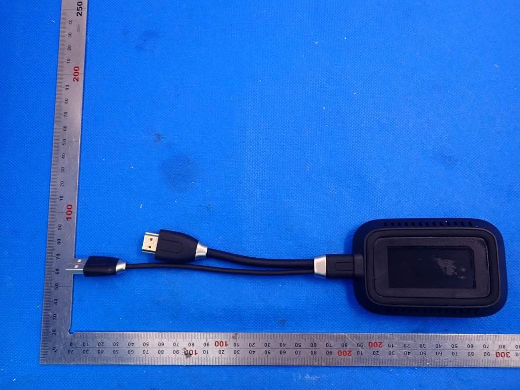
GSS-VS18189
Jan 24, 20212.4G & 5G WiFi ViewBoard Cast Button
Equipment Class
DTS - Digital Transmission System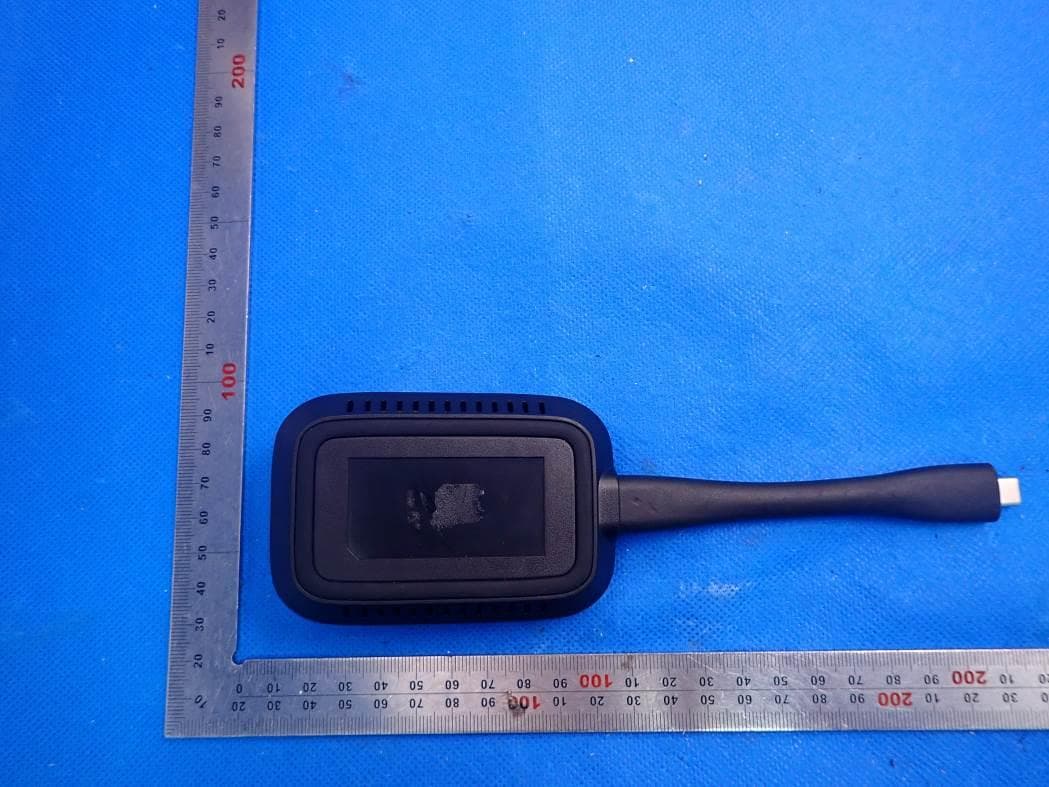
GSS-VS18188
Jan 19, 20212.4G & 5G WiFi ViewBoard Cast Button
Equipment Class
DTS - Digital Transmission System