GSSVSVPD10000203Wireless View Pad
ViewSonic Corporation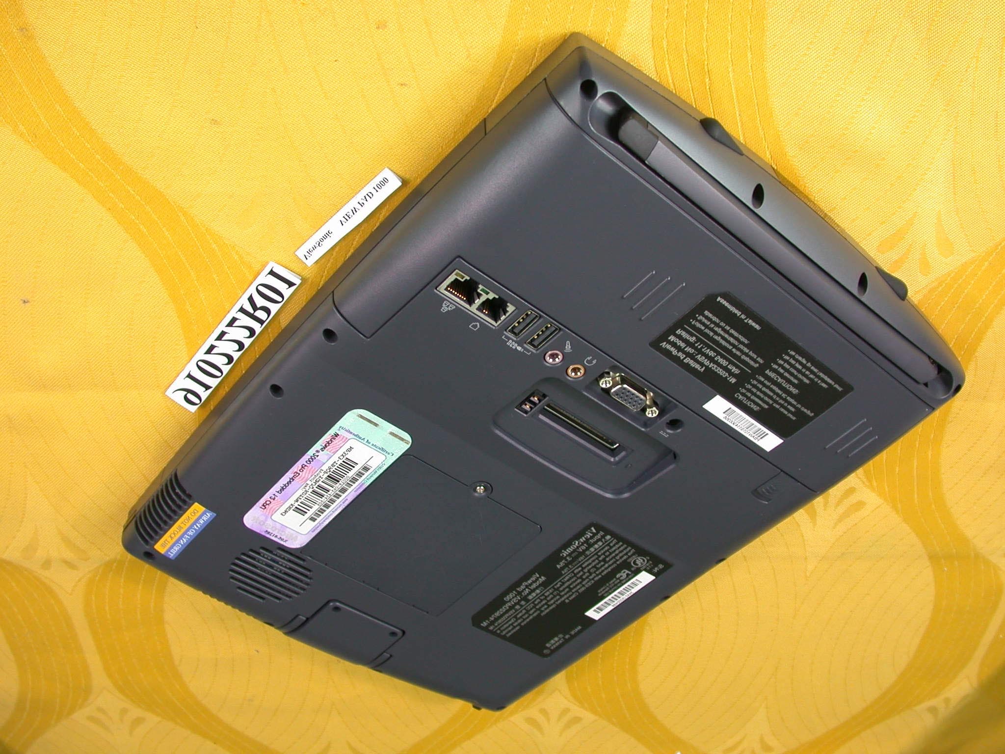
Click to zoom
Application Details
- Equipment Class
- DTS - Digital Transmission System
- Date of Grant
- Mar 27, 2002
- Application Purpose
- Original Equipment
- Date of Application
- Mar 27, 2002
- Equipment Note
- Wireless View Pad
- Frequency Range
- 2410.00000000 - 2462.00000000
- Company
- ViewSonic Corporation
- Country
- United States
Documents & Files
Document Text
Text extracted from the exhibit documents filed with the FCC. Open a document above to read the original.
Users Manual
Section 1 GETTING TO KNOW THE BASICS 1-1 SECTION 1 GETTING TO KNOW THE BASICS This section introduces the features and compo- nents of the tablet PC. 1-2 USER`S MANUAL Performance Features n High Performance Processor The tablet PC is equipped with Intel Celeron proces- sor with 128K L2 cache. n Advanced Graphic Engine An integrated AGP-bus 2D/3D video processor for high performance graphics. The video chip also incorporates a hardware-accelerated playback which gives you smooth MPEG video playback. 3D graphics capability also adds realism to PC games. n Upgradability * The system offers additional DRAM slot for expansion, allowing users to easily increase the system capacity as the need arises. n Bright LCD Display The sytem is equipped with 10.4-inch TFT XGA display panel for clear text and brilliant colors. n Portrait Mode or Landscape Mode To serve your specific needs, the tablet PC can be used in Portrait or Landscape mode. n Touch Screen Input The tablet PC has a built-in touch screen input device. This allows you to easily and quickly maneuver and create graphic designs or manage field applications. Note: Hard disk drive is not user- upgradable. If you need to upgrade the HDD, you need to return the unit to the dealer or manufacturer. ■ Audio Capability The system is equipped with internal audio and record and playback functions, including 3D (three-dimensional) audio, 64-voices DirectSound channel support, and built-in hardware wave-table. ■ Ethernet Adapter and Modem The system provides built-in Ethernet network adapter and 56K modem for communiction and connection flexibility. ■ Built-in Digital Camera The integrated digital camera allows you to take snapshots or record a video clip. ■ Wireless LAN The computer may be equipped with Wireless LAN (802.11) to connect to a wireless network. ■ Docking Station (Optional) The optional docking station not only provides all the necessary I/O ports, it also has a built-in CD-ROM or DVD-ROM for large data access or video disk playback. 1-3 Section 1 GETTING TO KNOW THE BASICS 1-4 USER`S MANUAL 1.Stylus The stylus (touch pen) works like a mouse. Use the tip to point to an icon on the LCD panel or draw a line in any graphic application. Tapping an icon twice in a quick session is similar to double-clicking with a mouse. System at a Glance Front View Section 1 GETTING TO KNOW THE BASICS 1-5 2.Ditigal Camera The built-in digital camera (up to 640x480 resolution) allows you to take photos or record a video clip. You must pre- install software that will work with the camera. See Factory CD-ROM disk for any bundled graphic software. The focus ring allows you to adjust focal length of the camera lens. Adjust the ring to for the sharpest focus. Go to How to Use the Digital Camera Section for more details. 3.Battery Status LED Flashing green light indicates the battery pack is being charged.... (See the LED Status Indicator Section for details.) 4.Power Status LED The multi-color LED indicates the power status of the tablet PC. (See the LED Status Indicator Section for details.) 5.WWW Internet Hot Key The `Internet Hot Key` launches the Internet Explore automatically. You will need to activate a utility program in the factory CD to make use of the key. (See side-note for Quick Keys installation.) 6.Email Hot Key The `Internet Hot Key` launches the MS Outlook Express. You will need to activate a utility program in the factory CD to make use of the key. (See side-note for Quick Keys installation.) 7.Power/Suspend Button The power/suspend button turns the system on and off and it also acts as a system suspend key. This tablet PC uses a special one-button design. Press momentarily to turn on the system. Press and hold for at least 3~4 seconds to turn off the system. In Windows 98 SE, ME, or 2000, how the power button should behave can be defined in Windows Power Management utility. Go to [Start > Settings > Control 1-6 USER`S MANUAL Panel > Power Management] to access the utility. Go to Section 2 for more details on system suspend function. 8.LCD Display The panel is where the system`s data is displayed. 9.Built-in Microphone The built-in microphone records sound. 10.Consumer Infrared Port (1) The CIR port is used to link with a CIR-type wireless keyboard. 11.Built-in Stereo Speakers The built-in speakers output the sound in stereo. 12.Stand The stand allows the tablet PC to be positioned vertically (Portrait Mode) or horizontally (Landscape Mode) on a desktop. 13.Rubber Feet The rubber feet allows the tablet PC to be positioned on its side on the desk. Note: If you encounter difficulties with IrDA (infrared port) operation, go to Section 5 to learn to solve the problems. Warning: Do not place any heavy objects on the LCD panel. It may damage the display. Note: The tablet PC can be positioned horizontally. You will need to rotate the display content 90 degrees via the `Pivot` software. Go to How to Use the Tablet PC in Landscape Mode Section to learn more. Section 1 GETTING TO KNOW THE BASICS 1-7 1.Built-in Antenna The antenna is used to transmit and receive data from another Bluetooth-enabled device / system. It should be fully extended for best result. Go to the Bluetooth Help Menu for operational tips. ( The Bluetooth application is contained in the Factory CD-ROM disk.) 2. Ventilation Grills The fan grills allow the air to circulate through the internal heat regulation system. Do not block the airway completely. Rear View 1-8 USER`S MANUAL 3.PC Card Slot (PCMCIA) and Card Eject Button The slot is where PC Card (PCMCIA) is inserted. Press the eject button to release the PC Card. 4.DIMM (DRAM) Expansion Slot Cover This is where two DIMM expansion slots are located. One of the slot may have been occupied by a dealer or manu- facturer pre-installed DIMM module. 5.Docking Port The docking port allows the tablet PC to connect to an optional docking station. Go to Chapter 5 for more details on the docking station. 6.Battery Pack and Battery Latch The batt…
Text truncated - open the document above for the full version.
Cover Letter(s)
American Telecommunications Certification Body Inc. 6731 Whittier Ave, McLean, VA 22101 March 22, 2002 RE: ViewSonic Corporation FCC ID: GSSVSVPD10000203 I have some confusion on this Application that I hope you can help me solve. 1.) Please provide a Block Diagram of the RF module. The diagrams we have only show the host layout. 2.) Please provide schematics of the RF module. If I have overlooked it, please indicate where and on what page they begin. 3.) The Manual on page 1-3 indicates this can be outfitted with an optional Bluetooth transmitter. This is at odds with the co-location prohibitions currently in effect for TCBs. Please show how the requirements of co-location do not apply if AmericanTCB is to complete this Application. 4.) Final page of Manual contains prohibition on co-location. However, until item #3 (above) is resolved, this language may not apply. 5.) A Limited Modular Approval (LMA) is being sought for this device. Please provide a separate letter showing how this device complies with the modular approval requirements and what Grant conditions would be appropriate for this LMA.. 6.) Are there any accessories available or under consideration where this device may be used either on the belt or on a lanyard around the neck or wrist? 7.) The External Photographs for this device do not match the drawings in the Manual. Please review and explain. 8.) The Internal Photos seem to match the External Photos, but again the form factor of the device shown does not match the drawings in the Manual. William H. Graff President and Examining Engineer mailto: [email protected] The items indicated above must be submitted before processing can continue on the above referenced application. Failure to provide the requested information may result in application termination. Correspondence should be considered part of the permanent submission and may be viewed from the Internet after a Grant of Equipment Authorization is issued. Please do not respond to this correspondence using the email reply button. In order for your response to be processed expeditiously, you must submit your documents through the AmericanTCB.com website. Also, please note that partial responses increase processing time and should not be submitted. Any questions about the content of this correspondence should be directed to the sender.
External Photos
Page 1 ANNEX PHOTOGRAPHS OF EUT Page 2
ID Label/Location Info
FCC ID LABEL LOCATION
Internal Photos
Page 3 Page 4
Internal Photos
Page 5 Page 6
Internal Photos
Page 7 Page 8
Internal Photos
Page 9
Operational Description
FCC ID: GSSVSVPD10000203 ADT No.910222R01 Operational Description The transmitter of the EUT is powered by Mini-PCI interface of UFL Pocket PC. The antenna is Dipole antenna, and there is no antenna connector. Under normal use condition, the user has to keep at least 20cm separation distance away from the radiator. Authorization of Limited Module Approval has been reguested on this product. For more detailed instruction, please take a look at the users manual. DSSS Information This device is Direct Sequence Spread Spectrum, the data is mixed by pseudorandom code which is an orthogonal code. The mixed data is digital modulated by BPSK and QPSK technique depends on the data rates. The CCK coding is applied for increasing the data rate, and also the processing gain will be increased. The bit rates are 1,2,5.5,11Mbps, the symbol rates are 1,1,1.375,1.375Mbps, the chip rates are always 11Mbps. So, the Chip/symbol is 11,11,8 and 8 respectively. Although the bit rate is higher, the processing gain is lower than 10, but the CCK coding used in higher bit rate will provide 2.2dB coding gain.
Test Report
FCC ID: GSSVSVPD10000203 Report No.: RF910222R01 1 Issued: March 19, 2002 FCC TEST REPORT REPORT NO.: RF910222R01 MODEL NO.: VSVPD22974-1M RECEIVED: February 22, 2002 TESTED: February 22 ~ March 15 , 2002 APPLICANT:ViewSonic Corporation ADDRESS:381, Brea Canyon Road Walnut, CA 91789, U.S.A ISSUED BY:Advance Data Technology Corporation LAB LOCATION:47 14th Lin, Chiapau Tsun, Linko, Taipei, Taiwan, R.O.C. This test report consists of 49 pages in total. It may be duplicated completely for legal use with the approval of the applicant. It should not be reproduced except in full, without the written approval of our laboratory. The client should not use it to claim product endorsement by CNLA, NVLAP or any government agencies. The test results in the report only apply to the tested sample. 0528 ILAC MRA Lab Code: 200102-0 FCC ID: GSSVSVPD10000203 Report No.: RF910222R01 2 Issued: March 19, 2002 Table of Contents 1CERTIFICATION ........................................................................................... 4 2SUMMARY OF TEST RESULTS................................................................... 5 3GENERAL INFORMATION ........................................................................... 6 3.1GENERAL DESCRIPTION OF EUT ............................................................. 6 3.2DESCRIPTION OF TEST MODES ............................................................... 7 3.3GENERAL DESCRIPTION OF APPLIED STANDARDS............................... 7 3.4DESCRIPTION OF SUPPORT UNITS.......................................................... 8 4TEST TYPES AND RESULTS ...................................................................... 9 4.1CONDUCTED EMISSION MEASUREMENT ................................................ 9 4.1.1LIMITS OF CONDUCTED EMISSION MEASUREMENT ............................. 9 4.1.2TEST INSTRUMENTS .................................................................................. 9 4.1.3TEST PROCEDURES................................................................................. 10 4.1.4TEST SETUP .............................................................................................. 10 4.1.5EUT OPERATING CONDITIONS.................................................................11 4.1.6TEST RESULTS.......................................................................................... 12 4.2RADIATED EMISSION MEASUREMENT ................................................... 18 4.2.1LIMITS OF RADIATED EMISSION MEASUREMENT................................. 18 4.2.2TEST INSTRUMENTS ................................................................................ 19 4.2.3TEST PROCEDURES................................................................................. 20 4.2.4TEST SETUP .............................................................................................. 21 4.2.5EUT OPERATING CONDITIONS................................................................ 21 4.2.6TEST RESULTS.......................................................................................... 22 4.36dB BANDWIDTH MEASUREMENT .......................................................... 27 4.3.1LIMITS OF 6dB BANDWIDTH MEASUREMENT........................................ 27 4.3.2TEST INSTRUMENTS ................................................................................ 27 4.3.3TEST PROCEDURE ................................................................................... 28 4.3.4TEST SETUP .............................................................................................. 28 4.3.5EUT OPERATING CONDITIONS ............................................................... 28 4.3.6TEST RESULTS.......................................................................................... 29 4.4MAXIMUM PEAK OUTPUT POWER .......................................................... 33 4.4.1LIMITS OF MAXIMUM PEAK OUTPUT POWER MEASUREMENT ........... 33 4.4.2TEST INSTRUMENTS ................................................................................ 33 4.4.3TEST PROCEDURES................................................................................. 34 4.4.4TEST SETUP .............................................................................................. 34 4.4.5EUT OPERATING CONDITIONS................................................................ 34 FCC ID: GSSVSVPD10000203 Report No.: RF910222R01 3 Issued: March 19, 2002 4.4.6TEST RESULTS.......................................................................................... 35 4.5POWER SPECTRAL DENSITY MEASUREMENT ..................................... 36 4.5.1LIMITS OF POWER SPECTRAL DENSITY MEASUREMENT ................... 36 4.5.2TEST INSTRUMENTS ................................................................................ 36 4.5.3TEST PROCEDURE ................................................................................... 37 4.5.4TEST SETUP .............................................................................................. 37 4.5.5EUT OPERATING CONDITIONS................................................................ 37 4.5.6TEST RESULTS.......................................................................................... 38 4.6BAND EDGES MEASUREMENT ................................................................ 42 4.6.1LIMITS OF BAND EDGES MEASUREMENT ............................................. 42 4.6.2TEST INSTRUMENTS ................................................................................ 42 4.6.3TEST PROCEDURE ................................................................................... 42 4.6.4EUT OPERATING CONDITION .................................................................. 43 4.6.5TEST RESULTS.......................................................................................... 43 4.7ANTENNA REQUIREMENT........................................................................ 46 4.7.1STANDARD APPLICABLE....................................…
Text truncated - open the document above for the full version.
Test Setup Photos
FCC ID: GSSVSVPD10000203 Report No.: RF910222R01 47 Issued: March 19, 2002 5 PHOTOGRAPHS OF THE TEST CONFIGURATION CONDUCTED EMISSION TEST FCC ID: GSSVSVPD10000203 Report No.: RF910222R01 48 Issued: March 19, 2002 RADIATED EMISSION TEST
Contact Information
Applicant
Nelson Chou(Sr. Compliance Manager)
Technical Contact
Advance Data Technology CorporationAlan Lane
[email protected]+886 3 327 0892
13-1, Lane 19, WenShan 3rd St · Taoyuan · Taiwan
Test Firm
Bureau Veritas CPS (H.K.) Ltd. Taoyuan BranchRichard Chen
Technical Specifications
| # | Rule Parts | Frequency Range | Power Output |
|---|---|---|---|
| 1 | 15C | 2.41 GHz - 2.46 GHz | 41.00 mW |
Other Applications from ViewSonic Corporation
GSSVS20085
Jun 12, 2024PJ-WPD-800
Equipment Class
DTS - Digital Transmission System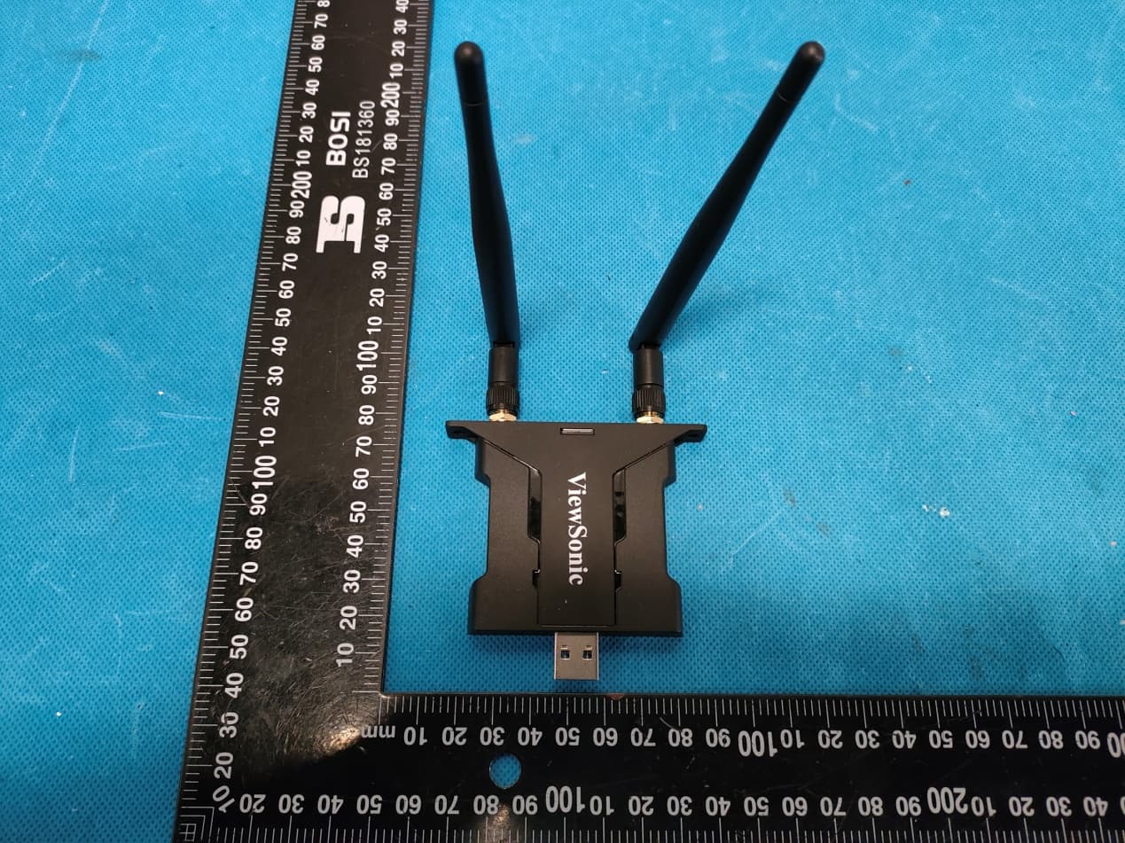
GSS-VS19147
Apr 06, 2022VB-WIFI-005
Equipment Class
NII - Unlicensed National Information Infrastructure TX
GSS-VS18518
Mar 10, 2021Bluetooth Conference Cam
Equipment Class
DSS - Part 15 Spread Spectrum Transmitter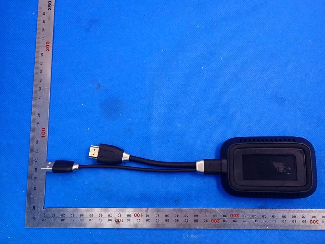
GSS-VS18189
Jan 24, 20212.4G & 5G WiFi ViewBoard Cast Button
Equipment Class
DTS - Digital Transmission System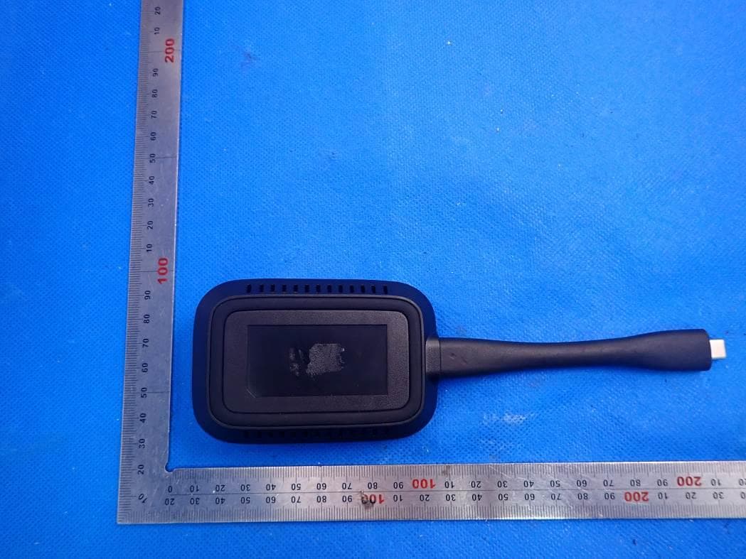
GSS-VS18188
Jan 19, 20212.4G & 5G WiFi ViewBoard Cast Button
Equipment Class
DTS - Digital Transmission System