GZ5224742ADSL2+ 802.11b/g Ethernet Modem
ARRIS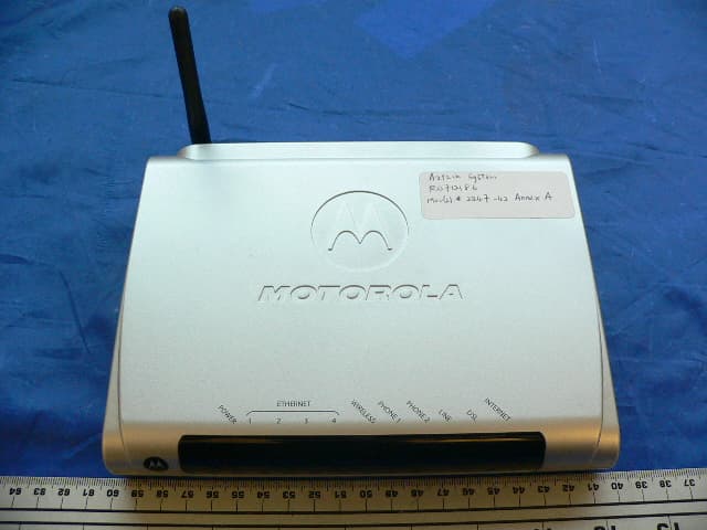
Click to zoom
Application Details
- Equipment Class
- DTS - Digital Transmission System
- Date of Grant
- Feb 04, 2008
- Application Purpose
- Original Equipment
- Date of Application
- Feb 04, 2008
- Equipment Note
- ADSL2+ 802.11b/g Ethernet Modem
- Frequency Range
- 2412.00000000 - 2462.00000000
- Company
- ARRIS
- Country
- United States
Documents & Files
Document Text
Text extracted from the exhibit documents filed with the FCC. Open a document above to read the original.
Users Manual
Administrator’s Handbook Embedded Software Version 7.7.4 Motorola Netopia ® 2200, 3300 and 7000 Series Gateways Administrator’s Handbook Copyright Copyright © 2007 by Motorola, Inc. All rights reserved. No part of this publication may be reproduced in any form or by any means or used to make any derivative work (such as translation, transformation or adaptation) without written permission from Motorola, Inc. Motorola reserves the right to revise this publication and to make changes in content from time to time without obligation on the part of Motorola to provide notification of such revision or change. Motorola provides this guide without warranty of any kind, either implied or expressed, including, but not limited to, the implied warranties of merchantability and fitness for a particular purpose. Motorola may make improvements or changes in the product(s) described in this manual at any time. MOTOROLA and the Stylized M Logo are registered in the US Patent & Trademark Office. Microsoft, Windows, Windows Me, and Windows NT are either trademarks or registered trademarks of Microsoft Corporation in the U.S and/or other countries. Macintosh is a registered trademark of Apple, Inc. Firefox is a registered trademark of the Mozilla Foundation. All other product or service names are the property of their respective owners. Motorola, Inc. 6001 Shellmound Street Emeryville, CA 94608 U.S.A. Part Number 6161244-00-01 Copyright Acknowledgments Because Motorola has included certain software source code in this product, Motorola includes the following text required by the respective copyright holders: Portions of this software are based in part on the work of the following: Copyright (c) 1998-2005 The OpenSSL Project. All rights reserved. Redistribution and use in source and binary forms, with or without modification, are permitted provided that the following conditions are met: 1. Redistributions of source code must retain the above copyright notice, this list of conditions and the following disclaimer. 2. Redistributions in binary form must reproduce the above copyright notice, this list of conditions and the following disclaimer in the documentation and/or other materials provided with the distribution. 3. All advertising materials mentioning features or use of this software must display the following acknowledgment: “This product includes software developed by the OpenSSL Project for use in the OpenSSL Toolkit. (http://www.openssl.org/)” 4. The names “OpenSSL Toolkit” and “OpenSSL Project” must not be used to endorse or promote products derived from this software without prior written permission. For written permission, please contact openssl- [email protected]. 5. Products derived from this software may not be called “OpenSSL” nor may “OpenSSL” appear in their names without prior written permission of the OpenSSL Project. 6. Redistributions of any form whatsoever must retain the following acknowledgment: “This product includes software developed by the OpenSSL Project for use in the OpenSSL Toolkit (http://www.openssl.org/)” THIS SOFTWARE IS PROVIDED BY THE OpenSSL PROJECT ``AS IS'' AND ANY EXPRESSED OR IMPLIED WARRANTIES, INCLUDING, BUT NOT LIMITED TO, THE IMPLIED WARRANTIES OF MERCHANTABILITY AND FITNESS FOR A PARTICULAR PURPOSE ARE DISCLAIMED. IN NO EVENT SHALL THE OpenSSL PROJECT OR ITS CONTRIBUTORS BE LIABLE FOR ANY DIRECT, INDIRECT, INCIDENTAL, SPECIAL, EXEMPLARY, OR CONSEQUENTIAL DAMAGES (INCLUDING, BUT NOT LIMITED TO, PROCUREMENT OF SUBSTITUTE GOODS OR SERVICES; LOSS OF USE, DATA, OR PROFITS; OR BUSINESS INTERRUPTION) HOWEVER CAUSED AND ON ANY THEORY OF LIABILITY, WHETHER IN CONTRACT, STRICT LIABILITY, OR TORT (INCLUDING NEGLIGENCE OR OTHERWISE) ARISING IN ANY WAY OUT OF THE USE OF THIS SOFTWARE, EVEN IF ADVISED OF THE POSSIBILITY OF SUCH DAMAGE. This product includes cryptographic software written by Eric Young ([email protected]). This product includes software written by Tim Hudson ([email protected]). Original SSLeay License /Copyright (C) 1995-1998 Eric Young ([email protected]) All rights reserved. This package is an SSL implementation written by Eric Young ([email protected]). The implementation was written so as to conform with Netscape’s SSL. This library is free for commercial and non-commercial use as long as the following conditions are adhered to. The following conditions apply to all code found in this distribution, be it the RC4, RSA, lhash, DES, etc., code; not just the SSL code. The SSL documentation included with this distribution is covered by the same copyright terms except that the holder is Tim Hudson ([email protected]). Copyright remains Eric Young's, and as such any Copyright notices in the code are not to be removed. If this package is used in a product, Eric Young should be given attribution as the author of the parts of the library used. This can be in the form of a textual message at program startup or in documentation (online or textual) provided with the package. Redistribution and use in source and binary forms, with or without modification, are permitted provided that the following conditions are met: 1. Redistributions of source code must retain the copyright notice, this list of conditions and the following disclaimer. 2. Redistributions in binary form must reproduce the above copyright notice, this list of conditions and the following disclaimer in the documentation and/or other materials provided with the distribution. 3. All advertising materials mentioning features or use of this software must display the following acknowledgement: “This product includes cryptographic software written by Eric Young ([email protected])” The word 'cryptographic' can be left out if the routines from the library being used are not cryptographic related :-). 4. If you include any Windows specific code (or a derivative thereof) from the apps directory (application code) you must include an acknowledgement: “This product includes software written by Tim Hudson (tjh@cryptsof…
Text truncated - open the document above for the full version.
Users Manual
171 Working with IP Filters and Filter Sets To work with filters and filter sets, begin by accessing the filter set pages. ☛ NOTE: Make sure you understand how filters work before attempting to use them. Read the section “Packet Filter” on page 163. The procedure for creating and maintaining filter sets is as follows: 1.Add a new filter set. See Adding a filter set, below. 2.Create the filters for the new filter set. See “Adding filters to a filter set” on page 172. 3.Associate the filter set with either the LAN or WAN interface. See “Associating a Filter Set with an Interface” on page 176. The sections below explain how to execute these steps. Adding a filter set You can create up to eight different custom filter sets. Each filter set can contain up to 16 output filters and up to 16 input filters. There can be a maximum of 32 filter rules in the system. To add a new filter set, click the Add button in the Filter Sets page. The Add Filter Set page appears. Enter new name for the filter set, for example Filter Set 1. To save the filter set, click the Submit button. The saved filter set is empty (contains no filters), but you can return to it later to add filters (see “Adding fi lters to a filter set”). ☛ NOTE: As you begin to build a filter set, and as you add filters, after your first entr y, the Alert icon Administrator’s Handbook 172 will appear in the upper right corner of the web page. It will remain until all of your changes are entered and validated. You need not immediately restart the Gateway until your fil- ter set is complete. See “Associating a Filter Set with an Interface” on page 176. Adding filters to a filter set There are two kinds of filters you can add to a filter set: input and output. Input filters check packets received from the Internet, destined for your network. Output filters check packets transmitted from your network to the Internet. Packets in Netopia Embedded Software Version 7.7.4 pass through an input filter if they originate from the WAN and through an output filter if they’re being sent out to the WAN. The process for adding input and output filters is exactly the same. The main difference between the two involves their reference to source and destination. From the perspective of an input filter, your local network is the destination of the packets it checks, and the remote network is their source. From the perspective of an output filter, your local network is the source of the packets, and the remote network is their destination. To add a filter, select the Filter Set Name to which you will add a filter, and click the Edit button. Type of filterSource meansDestination means Input filterThe remote networkThe local network Output filterThe local networkThe remote network The Motorola Netopia® Router input filter output filter LAN WAN packet packet 173 The Filter Set page appears. ☛ Note: There are two Add buttons in this page, one for input filters and one for output filters. In this section, you’ll learn how to add an input filter to a filter set. Adding an output filter works exactly the same way, providing you keep the different source and destination perspectives in mind. Administrator’s Handbook 174 1.To add a filter, click the Add button under Input Rules. The Input Rule Entr y page appears. 2.If you want the filter to forward packets that match its criteria to the destination IP address, check the Forward checkbox. If For ward is unchecked, packets matching the filter’s criteria will be discarded. 3.Enter the Source IP address this filter will match on. You can enter a subnet or a host address. 4.Enter the Source Mask for the source IP address. This allows you to further modify the way the filter will match on the source address. Enter 0.0.0.0 to force the filter to match on all source IP addresses, or enter 255.255.255.255 to match the source IP address exclusively. 5.Enter the Destination IP Address this filter will match on. You can enter a subnet or a host address. 6.Enter the Destination Mask for the destination IP address. This allows you to further modify the way the filter will match on the destination address. Enter 0.0.0.0 to force the filter to match on all destination IP addresses. 7.If desired, you can enter a TOS and TOS Mask value. See “Policy-based Routing using Filtersets” on page 177 for more information. 8.Select Protocol from the pull-down menu: ICMP, TCP, UDP, Any, or the number of another IP transport protocol (see the table on page 167). If Protocol Type is set to TCP or UDP, the settings for port comparison will appear. These settings only take effect if the Protocol Type is TCP or UDP. 9.From the Source Port Compare pull-down menu, choose a comparison method for the filter to use on a packet’s source port number. Then select Source Port and enter the actual source port number to match on (see the table on page 166). 10.From the Destination Port Compare pull-down menu, choose a comparison method for the filter to use on a packet’s destination port number. Then select Destination Port and enter the actual destination port number to match on (see the table on page 166). 175 11.When you are finished configuring the filter, click the Submit button to save the filter in the filter set. Viewing filters To display the table of input or output filters, select the Filter Set Name in the Filter Set page and click the Add or Edit button. The table of filters in the filtersets appears. Modifying filters To modify a filter, select a filter from the table and click the Edit button. The Rule Entr y page appears. The parameters in this page are set in the same way as the ones in the original Rule Entr y page (see “Adding fil- ters to a filter set” on page 172). Deleting filters To delete a filter, select a filter from the table and click the Delete button. Moving filters To reorganize the filters in a filter set, select a filter from the table and click the Move Up or Move Down button to place the filter in the desired priority position. De…
Text truncated - open the document above for the full version.
External Photos
Netopia Inc. FCC ID: GZ5224742 Report No.: R0712186-247 Page 74 of 77 FCC Part 15.247 Test Report EXHIBIT C - EUT PHOTOGRAPHS EUT – Top Side View EUT-Bottom Side View Netopia Inc. FCC ID: GZ5224742 Report No.: R0712186-247 Page 75 of 77 FCC Part 15.247 Test Report EUT- Ports Side View EUT-Power Supply View
ID Label/Location Info
Netopia Inc. FCC ID: GZ5224742 Report No.: R0712186-247 Page 67 of 77 FCC Part 15.247 Test Report EXHIBIT A - FCC ID LABEL INFORMATION FCC § 2.925 Identification of equipment (a) Each equipment covered in an application for equipment authorization shall bear a nameplate or label listing the following: (1) FCC Identifier consisting of the two elements in the exact order specified in §2.926. The FCC Identifier shall be preceded by the term FCC ID in capital letters on a single line, and shall be of a type size large enough to be legible without the aid of magnification. Example: FCC ID XXX123. XXX—Grantee Code 123—Equipment Product Code ID Label Requirements as per FCC § 15.19 (a) In addition to the requirements in part 2 of this chapter, a device subject to certification, or verification shall be labeled as follows: (3) All other devices shall bear the following statement in a conspicuous location on the device: This device complies with part 15 of the FCC Rules. Operation is subject to the following two conditions: (1) This device may not cause harmful interference, and (2) this device must accept any interference received, including interference that may cause undesired operation. (5) When the device is so small or for such use that it is not practicable to place the statement specified under paragraph (a) of this section on it, the information required by this paragraph shall be placed in a prominent location in the instruction manual or pamphlet supplied to the user or, alternatively, shall be placed on the container in which the device is marketed. However, the FCC identifier or the unique identifier, as appropriate, must be displayed on the device. Suggested Content on FCC ID Label As per FCC §15.17 (b)(4), the label shall not be a stick-on, paper label. The label on these products shall be permanently affixed to the product and shall be readily visible to the purchaser at the time of purchase, as described in Section 2.925(d) of this chapter. "Permanently affixed" means that the label is etched, engraved, stamped, silk-screened, indelibly printed, or otherwise permanently marked on a permanently attached part of the equipment or on a nameplate of metal, plastic, or other material fastened to the equipment by welding, riveting, or a permanent adhesive. The label must be designed to last the expected lifetime of the equipment in the environment in which the equipment may be operated and must not be readily detachable. Please refer to following labeling position photo Model: 2247-42-XXXX-YYYY-ZZZZ This device complies with part 15 of the FCC Rules. Operation is subject to the following two conditions: (1) This device may not cause harmful interference, and (2) this device must accept any interference received, including interference that may cause undesired operation. FCC ID: GZ5224742 Netopia Inc. Netopia Inc. FCC ID: GZ5224742 Report No.: R0712186-247 Page 68 of 77 FCC Part 15.247 Test Report Suggested Label Location on EUT EUT bottom View
Internal Photos
Netopia Inc. FCC ID: GZ5224742 Report No.: R0712186-247 Page 76 of 77 FCC Part 15.247 Test Report EUT- PCBA Component Side View EUT- PCBA Solder Side View Netopia Inc. FCC ID: GZ5224742 Report No.: R0712186-247 Page 77 of 77 FCC Part 15.247 Test Report EUT – Radio Card Detail View (RF Shielding Removed) Antenna Detail View
RF Exposure Info
Netopia Inc. FCC ID: GZ5224742 Report No.: R0712186-247 Page 11 of 77 FCC Part 15.247 Test Report 15.247 (i) and § 2.1091 - RF EXPOSURE According to §15.247(i) and §1.1307(b)(1), systems operating under the provisions of this section shall be operated in a manner that ensures that the public is not exposed to radio frequency energy level in excess of the Commission’s guidelines. According to §1.1310 and §2.1093 RF exposure is calculated. Limits for General Population/Uncontrolled Exposure Frequency Range (MHz) Electric Field Strength (V/m) Magnetic Field Strength (A/m) Power Density (mW/cm 2 ) Averaging Time (minutes) Limits for General Population/Uncontrolled Exposure 0.3-1.34 614 1.63 *(100) 30 1.34-30 824/f 2.19/f *(180/f 2 ) 30 30-300 27.5 0.073 0.2 30 300-1500 / / f/1500 30 1500-100,000 / / 1.0 30 f = frequency in MHz * = Plane-wave equivalent power density MPE Prediction Predication of MPE limit at a given distance Equation from page 18 of OET Bulletin 65, Edition 97-01 S = PG/4πR² Where: S = power density P = power input to antenna G = power gain of the antenna in the direction of interest relative to an isotropic radiator R = distance to the center of radiation of the antenna 802.11 b Mode Maximum peak output power at antenna input terminal (dBm): 20.8 Maximum peak output power at antenna input terminal (mW): 120.22 Prediction distance(cm): 20 Prediction frequency(MHz): 2437 Antenna Gain (typical)(dBi): 3 Maximum Antenna Gain(numeric): 1.995 Power density at prediction frequency at 20 cm (mW/cm 2 ): 0.0477 MPE limit for uncontrolled exposure at predication frequency(mW/cm 2 ): 1.0 Netopia Inc. FCC ID: GZ5224742 Report No.: R0712186-247 Page 12 of 77 FCC Part 15.247 Test Report 802.11 g Mode Maximum peak output power at antenna input terminal (dBm): 20.4 Maximum peak output power at antenna input terminal (mW): 109.65 Prediction distance(cm): 20 Prediction frequency(MHz): 2437 Antenna Gain (typical)(dBi): 3 Maximum Antenna Gain(numeric): 1.995 Power density at prediction frequency at 20 cm (mW/cm 2 ): 0.0435 MPE limit for uncontrolled exposure at predication frequency(mW/cm 2 ): 1.0 Test Result The predicted power density level at 20 cm is 0.0477 mW/cm 2 for 802.11 b mode, and 0.0435 mW/cm 2 for 802.11 g mode. Both are below the uncontrolled exposure limit of 1.0 mW/cm 2 at 2437 MHz. The EUT is used at least 20 cm away from user’s body. It is determined as mobile equipment and complies with the MPE limit.
Test Report
Note: This test report is for the customer shown above and their specific product only. It may not be duplicated or used in part without prior written consent from Bay Area Compliance Laboratories Corp. This report must not be used by the customer to claim product certification, approval, or endorsement by NVLAP, NIST, or any agency of the Federal Government (. FCC PART 15 SUBPART 247 MEASUREMENT AND TEST REPORT For Netopia Inc. 6001 Shellmound Street, 4th Floor Emeryville, CA 94608, USA FCC ID: GZ5224742 Report Type: Original Report Product Type: ADSL2+ 802.11b/g Ethernet Modem Test Engineers: Xiao Ming Hu and Jerry Wang Report Number: R0712186-247 Testing Dates: 2008-01-16 to 2008-01-24 Report Date: 2008-01-29 Reviewed By: Hans Mellberg, VP of Engineering Prepared By: (12) Bay Area Compliance Laboratories Corp. 1274 Anvilwood Ave Sunnyvale, CA 94089, USA Tel: (408) 732-9162 Fax: (408) 732 9164 Netopia Inc. FCC ID: GZ5224742 Report No.: R0712186-247 Page 2 of 77 FCC Part 15.247 Test Report TABLE OF CONTENTS GENERAL INFORMATION.............................................................................................................................................. 4 PRODUCT DESCRIPTION FOR EQUIPMENT UNDER TEST (EUT) .......................................................................................... 4 MECHANICAL DESCRIPTION OF EUT ................................................................................................................................ 4 EUT PHOTO...................................................................................................................................................................... 4 OBJECTIVE........................................................................................................................................................................ 5 RELATED SUBMITTAL(S)/GRANT(S) .................................................................................................................................. 5 TEST METHODOLOGY....................................................................................................................................................... 5 MEASUREMENT UNCERTAINTY......................................................................................................................................... 5 TEST FACILITY.................................................................................................................................................................. 5 SYSTEM TEST CONFIGURATION ................................................................................................................................. 7 JUSTIFICATION.................................................................................................................................................................. 7 EUT EXERCISE SOFTWARE............................................................................................................................................... 7 EQUIPMENT MODIFICATIONS............................................................................................................................................ 7 SPECIAL ACCESSORIES...................................................................................................................................................... 7 DEVICE SETTING: FOR TX OUTPUT POWER......................................................................................................................... 7 LOCAL SUPPORT EQUIPMENT:........................................................................................................................................... 7 EUT INTERNAL CONFIGURATION:..................................................................................................................................... 8 POWER SUPPLY INFORMATION.......................................................................................................................................... 8 EXTERNAL I/O CABLING LIST AND DETAILS..................................................................................................................... 8 TEST SETUP BLOCK DIAGRAM.......................................................................................................................................... 9 SUMMARY OF TEST RESULTS ...................................................................................................................................... 10 15.247 (i) and § 2.1091 - RF EXPOSURE........................................................................................................................... 11 §15.203 - ANTENNA REQUIREMENT............................................................................................................................. 13 APPLICABLE STANDARD................................................................................................................................................. 13 ANTENNA CONNECTED CONSTRUCTION......................................................................................................................... 13 §15.207 - CONDUCTED EMISSIONS ............................................................................................................................... 14 SECTION 15.207 CONDUCTED LIMITS:............................................................................................................................. 14 TEST SETUP..................................................................................................................................................................... 14 TEST EQUIPMENT LIST AND DETAILS.............................................................................................................................. 14 TEST PROCEDURE........................................................................................................................................................... 15 SUMMARY OF TEST R…
Text truncated - open the document above for the full version.
Test Setup Photos
Netopia Inc. FCC ID: GZ5224742 Report No.: R0712186-247 Page 69 of 77 FCC Part 15.247 Test Report EXHIBIT B - TEST SETUP PHOTOGRAPHS Conducted Emissions –Front View Conducted Emissions – Side View Netopia Inc. FCC ID: GZ5224742 Report No.: R0712186-247 Page 70 of 77 FCC Part 15.247 Test Report Unintentional Radiated Emissions – Front View Netopia Inc. FCC ID: GZ5224742 Report No.: R0712186-247 Page 71 of 77 FCC Part 15.247 Test Report Unintentional Radiated Emissions – Rear View Netopia Inc. FCC ID: GZ5224742 Report No.: R0712186-247 Page 72 of 77 FCC Part 15.247 Test Report Spurious Radiated Emissions – Front View Netopia Inc. FCC ID: GZ5224742 Report No.: R0712186-247 Page 73 of 77 FCC Part 15.247 Test Report Radiated Emissions – Rear View
Contact Information
Applicant
Wilson Wang(Hardware Engineer)
Test Firm
Bay Area Compliance LaboratoryJohn Chan
Technical Specifications
| # | Rule Parts | Frequency Range | Power Output |
|---|---|---|---|
| 2 | 15C | 2.41 GHz - 2.46 GHz | 109.70 mW |
Other Applications from ARRIS
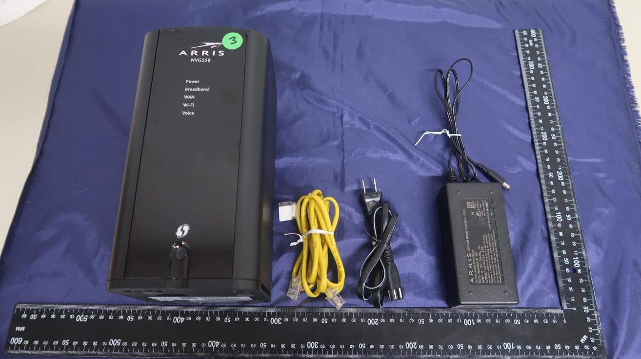
GZ5NVG558HX
Oct 09, 2020Fixed Broadband Gateway
Equipment Class
PCB - PCS Licensed Transmitter
GZ5NVG34NX4
Mar 18, 2015NVG34X Series VDSL2 Gateway
Equipment Class
DTS - Digital Transmission System
GZ5NVG599
Dec 11, 2013DSL
Equipment Class
DTS - Digital Transmission System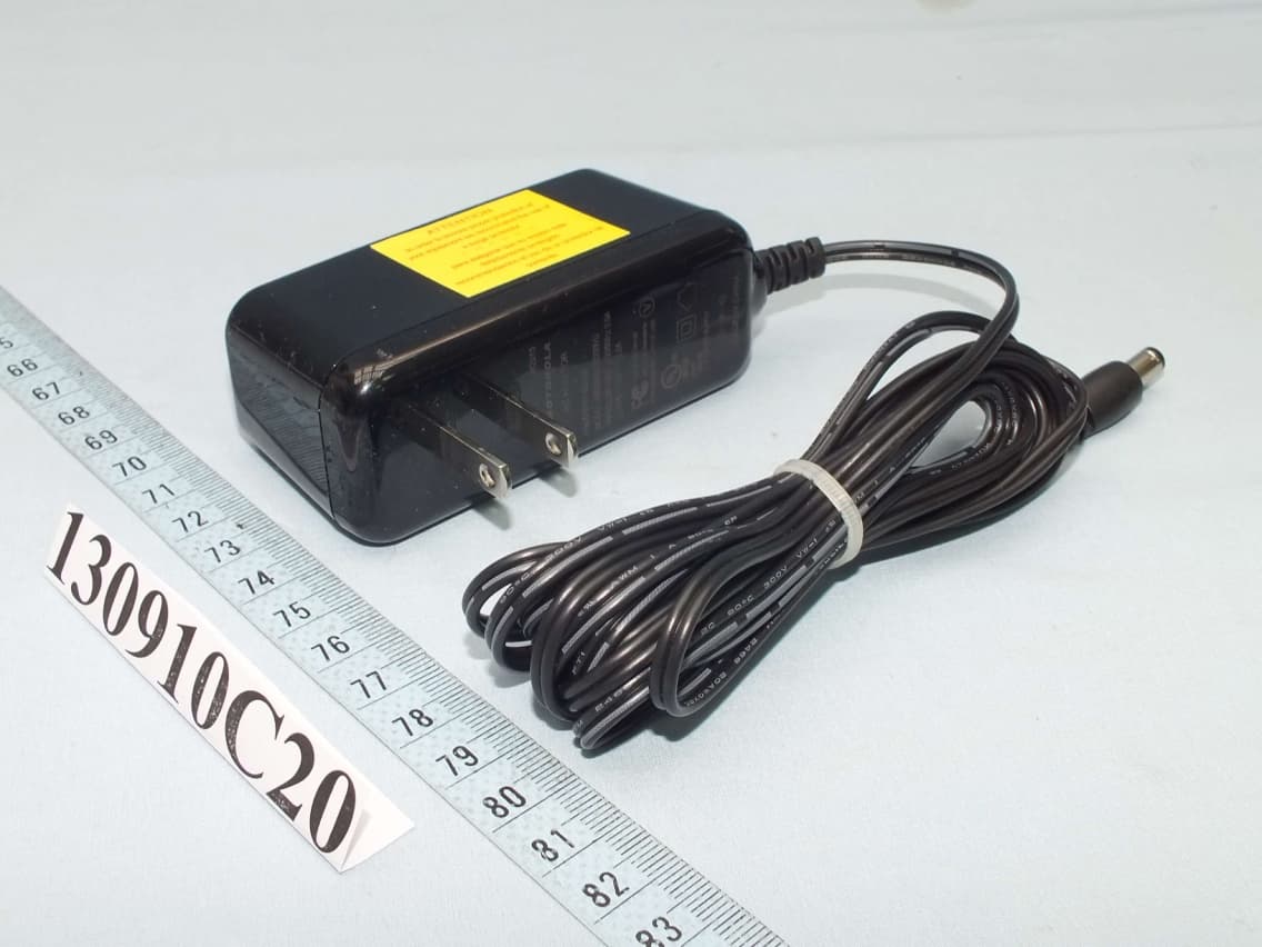
GZ5NVG595
Dec 09, 2013Fiber Business Gateway
Equipment Class
DTS - Digital Transmission System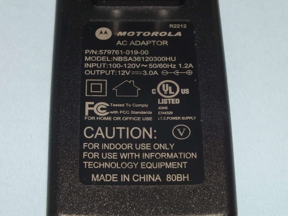
GZ5NVG589
Sep 17, 2012VDSL Gateway
Equipment Class
DTS - Digital Transmission System