H38PEM-500TWireless Microphone
SEIKAKU TECHNICAL GROUP LIMITED
Click to zoom
Application Details
- Equipment Class
- TBF - Licensed Broadcast Transmitter Held to Face
- Date of Grant
- Mar 20, 2002
- Application Purpose
- Original Equipment
- Date of Application
- Nov 20, 2001
- Equipment Note
- Wireless Microphone
- Frequency Range
- 694.30000000 - 704.30000000
- Country
- Samoa
Documents & Files
Document Text
Text extracted from the exhibit documents filed with the FCC. Open a document above to read the original.
Users Manual
PEM-500R ReceiverMaximum Audio Output Level 20 mW Minimum AudioOutput Load Impedance 16 Ω RF Sensitivity 2.5uV (-100 dB/12 dB SINAD) Squelch Threshold < -90 dB Spurious Rejection > 55 dBc Audio Output Connector 3.5 mm Stereo (Tip=left, Ring=Right, Sleeve=ground) Controls Volume adjust; limiter ON/OFF, power ON/OFF, STEREO/MONO select switches; 16-position channel selector switch Indicators Two-color (red/green) 3-way unit ON/Signal/Low Battery LED Power Requirements 9V alkaline battery Current Drain < 40 mA Battery Life Up to 6 hours, volume dependent Antenna Internal Dimensions 4.2" x 0.9" x 2.6" (106 x 23 x 66 mm) Weight 2.85 oz (80 Kg) SERVICE (U.S.) Should your Nady PEM-500 Wireless Personal In-Ear Monitor System require service, please contact the Nady Service Department via telephone at (510) 652-2411 or e-mail to [email protected] for a Return Authorization (R/A)Number and a service quote (if out of warranty). Make sure the R/A Number isclearly marked on the outside of the package that you send in and enclose acashier's check or money order (if not prepaid with a credit card). Ship the unitprepaid to: Nady Systems, Inc., Service Department, 6701 Shellmound Street,Emeryville, CA 94608. Include a brief description of the problem you areexperiencing.The warranty card enclosed with this system contains additional valuablewarranty and service information. Keep it in a safe place for possible futurereference. Do not attempt to service this unit yourself as it will void the warranty.(International) For service, please contact the Nady distributor in your country through the dealer from whom you purchased this product. 15 CONTENTS..............................................................................2INTRODUCTION ......................................................................3WARNING ..............................................................................4SYSTEM FEATURES ..................................................................5OPERATION ............................................................................6PEM-500T TRANSMITTER ........................................................6PEM-500R RECEIVER..............................................................10SPECIFICATIONS ....................................................................14SERVICE ................................................................................15 CONTENTS 2 Operating Frequency Range 696-865 MHz, country dependent Modulation Mono or stereo (MPX with pilot tone), FM: F3E+/- 60 KHz, nominal Audio Frequency Response 50 ~ 12,000 Hz T. H. D. < 1% Signal-to-Noise Ratio > 80 dB, with proprietary companding noise reduction Operating Range Up to 300 feet typical (depending on site conditions) PEM-500T TransmitterRF Output Power Max. 50 mW (country dependent) L/R Audio Line Inputs Input impedance 600 Ω Nominal Input Level 0 dBm Max. Input Level +6 dBm Headphones Out Power 100 mW max. @ 32 Ω , 190 mW @ 16 Ω Spurious Emission > -55 dBc Frequency Stability +/- 100 PPM Controls Power ON/OFF, STEREO/MONO, and channel select switches; input level, headphones monitor volume controls Connectors 1/4" stereo headphones monitor out, 1/4" TRS balanced mic input, balanced XLR L& R line input, and 2.1 mm barrel-type DC input jacks; BNC antenna socket Indicators Power ON LED; channel and 10-segment L/R audio input LED displays Antenna 1/4 wave rigid detachable, BNC mount Power Requirement 12-15V/ 500mA, AC/DC adapter supplied (UL/CSA approved 120VAC or CE approved 230VAC) Dimensions 8.27" x 9.13" x 1.73" (210 x 232 x 44 mm) Weight 2.98 lbs (1.35 Kg) SPECIFICATIONS 14 Thank you for purchasing a Nady PEM-500 Wireless Personal In-Ear MonitorSystem and congratulations on your choice. This system offers all of the advantagesof wireless in-ear monitoring–mobility, more focused audio, freedom from feedback,and elimination of transport issues associated with conventional floor monitors–aswell as the longterm health benefits of safe listening levels. For the first time, awireless in-ear monitor system combines state-of-the-art advanced frequency-agilePLL synthesized UHF technology, high-end performance, ease of use, andunprecedented affordability. The PEM-500 offers a choice of 16 user selectable UHFchannels in both the transmitter and receiver(s), as well as stereo (MPX system) ormono mode transmission. This system is indispensable for live-stage musicperformance, and is loaded with features previously found only in units costingseveral times more. This booklet gives instructions for the operation of the PEM-500 Wireless In-EarMonitor System. Please read the instructions for your system completely beforeoperating unit. This manual first lists the features of the PEM-500, and then takesyou step-by-step in explaining how to operate your new system, both transmitterand receiver. Each section gives you detailed operating instructions. Also included inthis manual are system specifications and servicing information. INTRODUCTION USING THIS MANUAL 3 24 28 20 21 5 29 23 24 27 22 18 18 18 19 13 26 25 USING THIS SYSTEM AT EXCESSIVE VOLUMES CAN CAUSE PERMANENTHEARING DAMAGE. ALWAYS USE AS LOW A VOLUME AS POSSIBLE.The Occupational Safety Health Administration (OSHA) has established thefollowing guidelines for maximum time exposure to sound pressure levels (SPL)before hearing damage occurs: 90 dB SPL @ 8 hours 95 dB SPL @ 4 hours 100 dB SPL @ 2 hours 105 dB SPL @ 1 hour 110 dB SPL @ 1/2 hour 115 dB SPL @ 15 minutes Aviod exposure to 120 dB or greater SPL or irreversible ear damage may result. (Note: It is difficult to measure the SPL present at the eardrum in live soundapplications. The volume present will be affected by the level setting of your PEM-500R, the ambient stage sound from your other instruments and speakers, and thequality of and fit of your in-ear speakers.) Always avoid prolonged listening at excessive sound pressure levels. Use thefollowing guidelines to use this system safely: 1.Turn up …
Text truncated - open the document above for the full version.
Block Diagram
1234 A B C D 4 321 D C B A Title NumberRevisionSize A4 Date:7-Nov-2001 Sheet of File:C:\PROGRAM FILES\DESIGN EXPLORER 99 SE\EXAMPLES\516TB4.DDBDrawn By: PEM-500T BLOCK DIAGRAM IEM-516T T.S HER 20011105 PRE-EMPHASIS IC2 NET-WORK ALC Dual preamplifier +8V MIC INPUT OR RF GAIN TR7 FILTER VCO +5V OSCILLATOR BPF ANT IC1 IC3 HEADPHONE MONITOR CONTROL IC4-IC7 DISPLAY LED EARPHONE IC8,9 STEREO SIGNAL INPUT R L Single serial input PLL frequency SynthesizerDevices inxluded 8-Bits CMOS Microcontroller 1CH 2CH15CH 16CH CHANNEL CONTROL RF GAIN TR11 RF GAIN TR8 IC10,11 IC1 STEREO MODULATOR
ID Label/Location Info
LABEL Format: This device complies with Part 74 of the FCC Rules FCC ID:H38PEM-500T LABEL Size: 85 X 10 mm LABEL Position:
Operational Description
PEM-500T 1. MIC INPUT OR L/R RCA INPUT=>IC1DUAL Preamplifier wit ALC LR The signal from MIC input or L/R RCA input will be dual pre-amplified by IC1 ( with ALC – Auto Level Control function ) and output a corresponding single signal or L/R signal . 2. The treble ( of the output ) will be improved first via the pre-emphasis net-work 3. IC3HEADPHONE AMPLIFIER MONITOREARPHONE The output signal can be also monitored via the earphone after it is amplified by IC3 ( headphone amplifier ). 4. IC8,IC9IC4~IC7LED DRIVE IC, LEDT Any change of the signal will be displayed on LED by the driving of IC4 ~ IC7 ( LED drive IC ) after it is amplified by another stage via IC8 & IC9. 5. LRIC2 The L/R signal after pre-emphasis can be stereo modulated via IC2 ( stereo modulator ) . 6. VCORF The modulated signal can be transmitted via the carrier produced by the VCO . To cover the scope which the receiver can effectively receive the amplifier chain is used to improve the RF gain to ensure the efficient transmission. 7. VCOIC13 The frequency produced by the VCO does also reach IC13 to perform the function of frequency phase detection. 8. SW2CHANNEL CONTROL SWITCH, SWITCH CHANGE DATA, IC13VCOCHARGE PUMPIC13IC10, IC11 CHANNEL The channel will be switched by SW2 ( channel control switch ) , and the data derived from the switch changing will be writed into IC13 to decode to perform the function of phase detection , accompany with the frequency produced by the VCO , a charge pump is output to control the transmission frequency . The same time , control signal from IC13 will also reach IC10 & IC11 to drive the seven section LED to display the channel being used .
Parts List/Tune Up Info
NoMaterial NoItem NameSpecificQuanityUnit ±PCS ±PCS ±PCS PCS IC PCS P-516T-RF-SMD863T6 NoMaterial NoItem NameSpecificQuanityUnit ±PCS ±PCS ±PCS PCS IC PCS P-516T-RF-SMD863T16 NoMaterial NoItem NameSpecificQuanityUnit ±PCS ±PCS ±PCS PCS IC PCS P-516T-RF-SMD794T16 NoMaterial NoItem NameSpecificQuanityUnit ±PCS ±PCS PCS IC PCS P-516T-RF-SMD694T16 NoMaterial NoItem NameSpecificQuanityUnit PCS P-516T-RF-DIP863T6 NoMaterial NoItem NameSpecificQuanityUnit PCS P-516T-RF-DIP863T16 NoMaterial NoItem NameSpecificQuanityUnit PCS P-516T-RF-DIP794T16 NoMaterial NoItem NameSpecificQuanityUnit PCS P-516T-RF-DIP694T16 NoMaterial NoItem NameSpecificQuanityUnit PCS PCS PCS PCS PCS PCS PCS PCS PCS PCS PCS PCS PCS PCS °PCS °PCS PCS PCS PCS PCS PCS PCS P-516T-RF-DIP NoMaterial NoItem NameSpecificQuanityUnit PCS ±PCS ±PCS ±PCS ±PCS ±PCS ±PCS ±PCS ±PCS ±PCS ±PCS ±PCS ±PCS ±PCS ±PCS ±PCS ±PCS ±PCS ±PCS ±PCS ±PCS ±PCS ±PCS ±PCS ±PCS ±PCS ±PCS ±PCS ±PCS ±PCS ±PCS ±PCS ±PCS ±PCS ±PCS ±PCS ±PCS ±PCS ±PCS ±PCS ±PCS ±PCS ±PCS ±PCS PCS PCS PCS P-516T-RF-SMD(NADY) PCS PCS PCS ±PCS ±PCS ±PCS ±PCS PCS PCS PCS PCS PCS PCS PCS PCS PCS PCS PCS PCS PCS PCS PCS PCS PCS PCS PCS PCS PCS NoMaterial NoItem NameSpecificQuanityUnit PCS PCS PCS PCS PCS PCS PCS PCS PCS PCS PCS PCS PCS PCS PCS PCS PCS PCS PCS PCS PCS PCS °PCS °PCS PCS PCS PCS PCS PCS PCS PCS PCS PCS PCS PCS PCS P-500T-PU(PEM-500) NoMaterial NoItem NameSpecificQuanityUnit circle markPCS PCS PCS PCS PCS PCS PCS PCS PCS plastic box markPCS plastic box markPCS W-P1(PEM-500T)-NADY NoMaterial NoItem NameSpecificQuanityUnit PCS PCS PCS PCS PCS PCS PCS PCS PCS PCS PCS PCS PCS PCS PCS PCS PCS PCS PCS PCS PCS PCS PCS self-adhere mark 87*32mmPCS PCS protective environment markPCS PCS PCS PCS PCS PCS PCS PCS PCS FCC safety standard mark (self-adhesive) PCS PCS PCS PCS PCS W-PEM-500T-NADY-120V
Test Report
Test Report --------------------------------------------------------------------------------- 2/47 Report No.: S0774553 Training Research Co., Ltd., TEL: 886-2-26935155, Fax: 886-2-26934440 Contents CHAPTER 0 APPLICATION FOR CERTIFICATION..........................4 CHAPTER 1 GENERAL...........................................................................5 1.1INTRODUCTION.....................................................................................5 1.2DESCRIPTION OF SUPPORT EQUIPMENT.................................................5 1.3CONFIGURATION OF TEST SETUP..........................................................6 1.4LOCATION OF THE MEASUREMENT SITE................................................7 1.5GENERAL TEST CONDITION...................................................................7 CHAPTER 2 CONDUCTED EMISSION TEST......................................8 2.1TEST CONDITION AND SETUP.................................................................8 2.2LIST OF TEST INSTRUMENT...................................................................8 2.3CONDUCTED TEST PLACEMENT: (PHOTOGRAPHS).................................9 2.4CONDUCTED EMISSION TEST RESULT..................................................10 CHAPTER 3 POWER OUTPUT MEASUREMENT.............................13 3.1RULES AND SPECIFICATION LIMITS.....................................................13 3.2TEST CONDITION AND SETUP...............................................................13 3.4MEASUREMENT RESULT.....................................................................16 CHAPTER 4 MODULATION CHARACTERISTICS MEASUREMENT .............................................................................................19 4.1RULES AND SPECIFICATION LIMITS.....................................................19 4.2TEST CONFIGURATION & LIST OF TEST INSTRUMENTS........................19 4.3LIST OF TEST INSTRUMENT..................................................................20 4.4FREQUENCY RESPONSE OF AUDIO MODULATION CIRCUIT AND LOW PASS FILTER MEASUREMENT CONDITION & SETUP...................20 4.5MODULATION LIMITING MEASUREMENT CONDITION & SETUP...........22 Test Report --------------------------------------------------------------------------------- 3/47 Report No.: S0774553 Training Research Co., Ltd., TEL: 886-2-26935155, Fax: 886-2-26934440 CHAPTER 5 OCCUPIED BANDWIDTH MEASUREMENT...............25 5.1RULES AND SPECIFICATION LIMITS.....................................................25 5.2TEST CONFIGURATION & LIST OF TEST INSTRUMENTS........................25 5.3LIST OF TEST INSTRUMENT.................................................................25 5.4MEASUREMENT PROCEDURE...............................................................26 5.5MEASUREMENT RESULT.....................................................................26 CHAPTER 6 FIELD STRENGTH OF SPURIOUS RADIATION MEASUREMENT ..............................................................32 6.1RULES AND SPECIFICATION LIMITS.....................................................32 6.2MEASUREMENT CONDITION & SETUP.................................................32 6.3LIST OF MEASUREMENT INSTRUMENTS...............................................35 6.4MEASUREMENT RESULT:.....................................................................36 CHAPTER 7 FREQUENCY STABILITY TOLERANCE MEASUREMENT ..............................................................42 7.1RULES AND SPECIFICATION LIMITS.....................................................42 7.2MEASUREMENT CONDITION & SETUP WITH TEMPERATURE VARIATION........................................................................................42 7.3LIST OF MEASUREMENT INSTRUMENTS WITH TEMPERATURE VARIATION LIST OF TEST INSTRUMENT..............................................42 7.4MEASUREMENT CONFIGURATION OF TEMPERATURE VARIATION TEST: ..............................................................................43 7.5MEASUREMENT RESULT WITH TEMPERATURE VARIATION.................44 7.6MEASUREMENT CONDITION & SETUP WITH VOLTAGE VARIATION.....46 7.7CONFIGURATION OF VOLTAGE VARIATION TEST................................46 7.8MEASUREMENT RESULT WITH VOLTAGE VARIATION.........................47 Test Report --------------------------------------------------------------------------------- 4/47 Report No.: S0774553 Training Research Co., Ltd., TEL: 886-2-26935155, Fax: 886-2-26934440 Chapter 0 Application for Certification 74.861( e )( 2 ):Transmitters may be either crystal controlled or frequency synthesized. ( ) crystal controlled ( X ) frequency synthesized 2.1033( c )( 1 ):Sekaku Electron Industry Co., Ltd. – applicant and manufacturer 2.1033( c )( 2 ):The equipment is a transmitter, wireless microphone Model No.: PEM-500T 2.1033( c )( 3 ):Quantity production is planned. See Exhibit C 2.1033 ( c )( 4 ):Type of emission – F3E- FM Modulation 2.1033( c )( 5 ):100Hz ~ 15kHz 2.1033( c )( 6 ):15.6 mW 2.1033( c )( 7 ):Specification of 250 mW is met by the equipment in the applicable Part 74.861 (e)(1)(ii) 2.1033 ( c )( 8 ):Final RF amplifier stage current : 400mA 2.1033( c )( 9 ):Description follows 2.1033( c )( 10 ):Complete circuit diagrams are included. No modification was made 2.1033( c )( 11 ):See Exhibit A. Instruction sheet to user included 2.1033( c )( 12 ):See Exhibit F. 2.1033( c )( 13 ):N/A 2.1033( c )( 14 ):Description follows. 2.1033( c )( 15 ) :N/A 2.1033( c )( 16 ):N/A 2.1033( c )( 17 ):N/A Test Report --------------------------------------------------------------------------------- 5/47 Report No.: S0774553 Training Research Co., Ltd., TEL: 886-2-26935155, Fax: 886-2-26934440 Chapter 1 GENERAL 1.1Introduction The following measurement report is submitted on behalf of Sekaku Electron Industry Co., Ltd. in support of a wireless microphone certification in accordance with FCC Rules. 2.1031, 2.1046, 2.1047, 2.1049, 2.1053, 2.1055, 74.801 and 74.861. Description of EUT: EUT:WIRELESS MICROPHONE Model No.:PEM…
Text truncated - open the document above for the full version.
Test Report
Test Report ------------------------------------------------------------------------------ 1/19 Report No.: S0774553 Training Research Co., Ltd., TEL: 886-2-26935155, Fax: 886-2-26934440 Stereo (L+R) of Occupied Bandwidth Measurement 1. Rules and Specification Limits 2.1049( c )( 1 ): ANSI/ TIA / EIA-603-1992, Paragraph 2.2.11. 74.861( e )( 3 ): Any form of modulation may be used. A maximum deviation of 75kHz is permitted when frequency modulation is employed. 74.861( e )( 5 ): The operation bandwidth shall not exceed 200kHz. 2. Test Configuration & List of Test Instruments 3. List of test Instrument Instrument Name Model No. Brand Input Impedance Spectrum analyzer (9K~1.8GHz) 8594EM HP 50 Preamplifier (30MHz~1GHz) TRC001 TRC 50 Signal Generator 50 MHz HP8116A HP 50 Signal Generator HP8904A HP 50 Bi-log Antenna CBL6141A SCHAFFNER 50 Power Supply HP 8594EM Analyzer Preamplifier EUT HP 8116A Signal Generator Antenna Mouth Simulator HP8904A S.G. Test Report ------------------------------------------------------------------------------ 2/19 Report No.: S0774553 Training Research Co., Ltd., TEL: 886-2-26935155, Fax: 886-2-26934440 4. Measurement Procedure 1. Connect the EUT as Section 2 . 2. Plot the unmodulated chart shows on spectrum. 3. Set the output of the signal generator to 1kHz, 2.5kHz, 9.448kHz and 15kHz. Increase the amplitude of the signal, while monitoring the modulation meter. Until modulation is max. Measure the bandwidth under 26 dB compared to the unmodulated fundamental carrier peak level of the modulated signal displayed on the spectrum analyzer. 4. The occupied Bandwidth was measured as follow pages. Test Report ------------------------------------------------------------------------------ 3/19 Report No.: S0774553 Training Research Co., Ltd., TEL: 886-2-26935155, Fax: 886-2-26934440 Unmodulation Test Report ------------------------------------------------------------------------------ 4/19 Report No.: S0774553 Training Research Co., Ltd., TEL: 886-2-26935155, Fax: 886-2-26934440 L+R, 1KHz (Microphone Input 2.5KHz) Test Report ------------------------------------------------------------------------------ 5/19 Report No.: S0774553 Training Research Co., Ltd., TEL: 886-2-26935155, Fax: 886-2-26934440 L+R,1KHz (Microphone Input 2.5KHz) Test Report ------------------------------------------------------------------------------ 6/19 Report No.: S0774553 Training Research Co., Ltd., TEL: 886-2-26935155, Fax: 886-2-26934440 L+R 1KHz (Microphone Input 10KHz) Test Report ------------------------------------------------------------------------------ 7/19 Report No.: S0774553 Training Research Co., Ltd., TEL: 886-2-26935155, Fax: 886-2-26934440 L+R 1KHz (Microphone Input 10KHz) Test Report ------------------------------------------------------------------------------ 8/19 Report No.: S0774553 Training Research Co., Ltd., TEL: 886-2-26935155, Fax: 886-2-26934440 L+R 2.5KHz (Microphone Input 2.5KHz) Test Report ------------------------------------------------------------------------------ 9/19 Report No.: S0774553 Training Research Co., Ltd., TEL: 886-2-26935155, Fax: 886-2-26934440 L+R 2.5KHz (Microphone Input 2.5KHz) Test Report ------------------------------------------------------------------------------ 10/19 Report No.: S0774553 Training Research Co., Ltd., TEL: 886-2-26935155, Fax: 886-2-26934440 L+R 2.5KHz (Microphone Input 10KHz) Test Report ------------------------------------------------------------------------------ 11/19 Report No.: S0774553 Training Research Co., Ltd., TEL: 886-2-26935155, Fax: 886-2-26934440 L+R 2.5KHz (Microphone Input 10KHz) Test Report ------------------------------------------------------------------------------ 12/19 Report No.: S0774553 Training Research Co., Ltd., TEL: 886-2-26935155, Fax: 886-2-26934440 L+R 10KHz (Microphone Input 2.5KHz) Test Report ------------------------------------------------------------------------------ 13/19 Report No.: S0774553 Training Research Co., Ltd., TEL: 886-2-26935155, Fax: 886-2-26934440 L+R 10KHz (Microphone Input 2.5KHz) Test Report ------------------------------------------------------------------------------ 14/19 Report No.: S0774553 Training Research Co., Ltd., TEL: 886-2-26935155, Fax: 886-2-26934440 L+R 10KHz (Microphone Input 10KHz) Test Report ------------------------------------------------------------------------------ 15/19 Report No.: S0774553 Training Research Co., Ltd., TEL: 886-2-26935155, Fax: 886-2-26934440 L+R 10KHz (Microphone Input 10KHz) Test Report ------------------------------------------------------------------------------ 16/19 Report No.: S0774553 Training Research Co., Ltd., TEL: 886-2-26935155, Fax: 886-2-26934440 L+R 15KHz (Microphone Input 2.5KHz) Test Report ------------------------------------------------------------------------------ 17/19 Report No.: S0774553 Training Research Co., Ltd., TEL: 886-2-26935155, Fax: 886-2-26934440 L+R 15KHz (Microphone Input 2.5KHz) Test Report ------------------------------------------------------------------------------ 18/19 Report No.: S0774553 Training Research Co., Ltd., TEL: 886-2-26935155, Fax: 886-2-26934440 L+R 15KHz (Microphone Input 10KHz) Test Report ------------------------------------------------------------------------------ 19/19 Report No.: S0774553 Training Research Co., Ltd., TEL: 886-2-26935155, Fax: 886-2-26934440 L+R 15KHz (Microphone Input 10KHz)
Contact Information
Applicant
Henry lee(R&D)
Technical Contact
TRAINING RESEARCH CO., LTD.JACK TSAI
[email protected]886-2-26935155
NO. 2, LANE 194, HUAN HO STREET, · TAIPEI HSIEN, · Taiwan
Test Firm
Training Research Co., Ltd.Jack Tsai
Technical Specifications
| # | Rule Parts | Frequency Range | Power Output | Emission | Tolerance |
|---|---|---|---|---|---|
| 1 | 74 | 694.3 MHz - 704.3 MHz | 15.60 mW | 106KF3E | 0.0050000000 % |
Other Applications from SEIKAKU TECHNICAL GROUP LIMITED
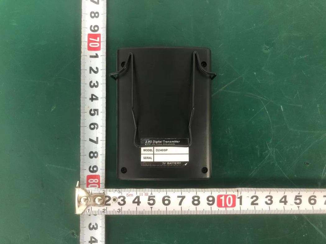
H38D2400P
Nov 26, 20252.4G Digital Transmitter
Equipment Class
DTS - Digital Transmission System
H38-RABT-ATS2819
May 09, 2023Bluetooth Module
Equipment Class
DTS - Digital Transmission System
H38WS-5
Oct 10, 2020PORTABLE SOUND SYSTEM WITH BLUETOOTH
Equipment Class
DSS - Part 15 Spread Spectrum Transmitter
H38WS-6
Sep 22, 2020PORTABLE SOUND SYSTEM WITH BLUETOOTH
Equipment Class
DSS - Part 15 Spread Spectrum Transmitter
H38WT-X
May 05, 2020PLL UHF Creative pen-shape microphone System
Equipment Class
DWM - Part 15 Wireless Microphone