H38VT2001Wireless Microphone
SEIKAKU TECHNICAL GROUP LIMITED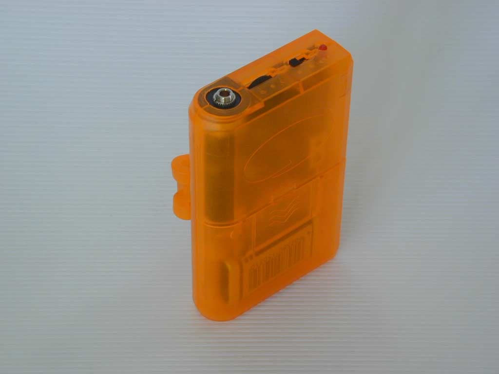
Click to zoom
Application Details
- Equipment Class
- TNT - Licensed Non-Broadcast Transmitter Worn on Body
- Date of Grant
- Sep 08, 2002
- Application Purpose
- Original Equipment
- Date of Application
- Aug 15, 2002
- Equipment Note
- Wireless Microphone
- Frequency Range
- 174.00000000 - 216.00000000
- Country
- Samoa
Documents & Files
Document Text
Text extracted from the exhibit documents filed with the FCC. Open a document above to read the original.
Cover Letter(s)
EMV-Pr ̧fzentrum EMI/EMC-Testcenter Hausanschrift: Sparkasse (BLZ 742 500 00) 14 076 Handelsregister Straubing ƒussere Fr ̧hlingstrasse 45 ! D-94315 Straubing Deutsche Bank (BLZ 750 700 13) 9 855 255 HRB-Nr. 9302 Telefon (0 94 21) 55 22-0 Dresdner Bank (BLZ 700 800 00) 0 803 965 300 Gesch‰ftsf ̧hrer: Telefax (0 94 21) 55 22-99 HypoVereinsbank (BLZ 742 200 75) 2 615 649 Johann Roidt, Manfred Amann [email protected] ! http://www.senton.de Postgiro N ̧rnberg (BLZ 760 100 85) 1 778 87 857 Senton GmbH ! ƒussere Fr ̧hlingstrasse 45 ! D-94315 Straubing Timothy R. Johnson American TCB 2002-08-16 In reference to FCC ID H38VT2001 1) DC voltages/currents applied into the several elements of the final radio frequency amplifying device according to section 2.1033 ( c ) (8) The input power to the final stage (TR7) was measured with a fresh 9 V battery. Input power for 9.0 V operation (9.0V) (4.3 mA) = 38.7 milliWatts 2) Tune up procedure over power range according to section 2.1033 ( c ) (9) a) Pick up the transmitter RF signal by an inductive coupling loop placed close to the unit. b) Connect the pick up device to the sensitive input of a radio communication tester c) Adjust T1 for proper transmitter frequency d) Adjust T2, T3 and VC1 for maximum output power e) Adjust L3, L4, L7, L8, VC3 and VC 4 for maximum output power while keeping harmonics at minimum. f) Repeat steps d) and e) if necessary 3) The description of test procedures in our report template includes all tests which might be applicable. The description of a test here does not imply that testing is required for this particular product. 4) Substitution method has been used, see clause 6.2 of the report. 5) The power values given in the report are correct. The test site and the anechoic chamber have been carefully verfified after testing this product to make sure that that this unexpected result is correct. 6) The above said applies also to spurious emission data. 7) A sample calculation is given on pages 24, 25 and 26. The correction factor presents the overall attenuation including gain of receiving antenna and cable losses. A full set of substitution factors has been determined for our test sites and will be kept current according to the requirements of our ISO 17025 compliant quality system. Senton GmbH Johann Roidt
Cover Letter(s)
American Telecommunications Certification Body Inc. 6731 Whittier Ave, McLean, VA 22101 August 16, 2002 RE: Sekaku Electron Industry Co., Ltd. FCC ID: H38VT2001 After a review of the submitted information, I have a few comments on the above referenced Application. 1) Please provide the "DC voltages/currents applied into the several elements of the final radio frequency amplifying device for normal operation over the power range" as specified by 2.1033(c)(8). 2) Please provide "Tune up procedure over power range" as specified by 1.1033(c)(9). 3) The test report section 6.1.1 is for conducted maximum transmitter power. However, no data was found for this section. Please comment. Note: Spurious conducted emissions were also not supplied. 4) It is not clear from the test data or measuring method if the substitution method was applied, or if general radiated field strength emissions were applied. Please note that the FCC required the substitution methods for these tests. Please provide further information. 5) The 731 form states the output power is 2 mW, while the test results given show 0.02 mW. This is a difference of 20 dB. Please explain. (Note: 0.02 mW power is lower than we would expect, many wireless micophones in this frequency range are around 10 mW. In fact the specification sheet given in the users manual does state 10 mW). 6) Given the concern with the output power above, please confirm the validity of the spurious emissions. 7) Please show how the limit was calculated for pages 24, 25, & 26 of 37. 8) FYI, the Current version of the EIA/TIA-603 is August 15, 2001. Timothy R. Johnson Examining Engineer Direct Phone: 404-414-8071 mailto: [email protected] The items indicated above must be submitted before processing can continue on the above referenced application. Failure to provide the requested information may result in application termination. Correspondence should be considered part of the permanent submission and may be viewed from the Internet after a Grant of Equipment Authorization is issued. Please do not respond to this correspondence using the email reply button. In order for your response to be processed expeditiously, you must submit your documents through the AmericanTCB.com website. Also, please note that partial responses increase processing time and should not be submitted. Any questions about the content of this correspondence should be directed to the sender.
Cover Letter(s)
Request for Confidentiality 15 July 2002 American Telecommunications Certification Body, Inc. 6731 Whittier Avenue Suite C110 McLean, VA 22101 RE: Certification Application FCC ID: H38VT2001 Please be advised that the following information is to be held confidential and behalf of Sekaku Electron Industry Co. Ltd.: • Description of Operation • Schematics • Block Diagram • Parts Lists The application contains technical information which Sekaku Electron Industry Co. Ltd. deems to be trade secrets and proprietary. If made public, the information might be used to the disadvantage of the applicant in the market place. Thank you for your attention to this matter. Signatory
External Photos
FCC ID: H38VT2001 External Photos Page 1 of 3 FCC ID: H38VT2001 External Photos Page 2 of 3 FCC ID: H38VT2001 External Photos Page 3 of 3
ID Label/Location Info
FCC ID: H38VT2001
Internal Photos
FCC ID: H38VT2001 Internal Photos Page 1 of 3 FCC ID: H38VT2001 Internal Photos Page 2 of 3 FCC ID: H38VT2001 Internal Photos Page 3 of 3
Test Report
EMV-Prüfzentrum EMI/EMC-Testcenter FCC-ID: H38xxxxx Test Report No. 56408-20405 Page 1 of 37 Pages Straubing, 09 September 2002 T E S T - R E P O R T No. 56408-20405 for VT-22P Wireless microphone transmitter Applicant: SEKAKU Electron Industry Co. Ltd. Purpose of testing: To show compliance with FCC Code of Federal Regulations, Part 15 Subpart H, § 74.861 Note: The test data of this report relate only to the individual item which has been tested. This report shall not be reproduced except in full extent without the written approval of the testing laboratory. EMV-Prüfzentrum EMI/EMC-Testcenter FCC-ID: H38xxxxx Test Report No. 56408-20405 Page 2 of 37 Pages Table of Contents 1. Administrative Data.................................................................................... 3 2. Identification of Test Laboratory................................................................. 4 3. Summary of Test Results........................................................................... 5 4. Operation Mode of EUT ............................................................................. 6 5. Configuration of EUT and Peripheral Devices ........................................... 7 6. Measuring Methods ................................................................................... 8 6.1. Maximum Transmitter Power (§ 2.1046 (a), 74.861 (e))...................... 8 6.2. Mean power of emissions 30 MHz - 1 GHz (§ 74.861.e.6.iii) ....................................................................................... 9 6.3. Radiated Emission 1 GHz - 2.5 GHz (§ 74.861.e.6.iii) ...................... 10 6.4. Emission Masks (Occupied Bandwidth) § 2.1049 (c) (1) ................... 11 6.5. Audio Frequency Response, 2.1047 (a) ............................................ 11 6.5. Audio Frequency Response, 2.1047 (a) ............................................ 12 6.6. Modulation Limiting, § 2.1047 (b) ...................................................... 12 6.6. Modulation Limiting, § 2.1047 (b) ...................................................... 13 6.7. Frequency Stability (Temperature Variation), § 2.1055 (a) (1)................................................................................................. 13 6.7. Frequency Stability (Temperature Variation), § 2.1055 (a) (1)................................................................................................. 14 6.8. Frequency Stability (Voltage Variation), § 2.1055 (b) (1)................... 15 7. Equipment List ......................................................................................... 16 8. Photographs Taken During Testing ......................................................... 18 9. List of Measurements............................................................................... 22 10. Referenced Regulations .......................................................................... 36 11. Charts taken during testing ...................................................................... 37 EMV-Prüfzentrum EMI/EMC-Testcenter FCC-ID: H38xxxxx Test Report No. 56408-20405 Page 3 of 37 Pages 1. Administrative Data Test item (EUT) VT-22P Type designation VT-22P Serial number(s): 001 Type of equipment: Wireless microphone transmitter Parts/accessories: --- FCC-ID: H38VT2001 Technical data Frequency range 174-216 MHz Operational frequency 3 Samples: 175.000 MHz, 199.820 MHz, 214.820 MHz Type of modulation 100KF3E Pulse frequency N/A Pulse width N/A Antenna Integrated Power supply 9 V Battery Applicant: (full address) SEKAKU Electron Industry Co. Ltd. No. 1 Lane 17, Sec. 2, Han Shi West Road Taichung 401, Taiwan, R.O.C. Contract identification: --- Contact person: Joan Wu Manufacturer: SEKAKU Electron Industry Co. Ltd. Application details Receipt of EUT: June 17, 2001 Date of test: July, 2001 Note: Responsible for testing: Johann Roidt Responsible for test report: Johann Roidt EMV-Prüfzentrum EMI/EMC-Testcenter FCC-ID: H38xxxxx Test Report No. 56408-20405 Page 4 of 37 Pages 2. Identification of Test Laboratory Test Laboratory: Senton GmbH EMI/EMC Test Center (full address): Aeussere Fruehlingstrasse 45 D-94315 Straubing Germany Contact person: Mr. Johann Roidt Communication: Telephone +49 94 21 55 22-0 Fax +49 94 21 55 22-99 eMail: [email protected] FCC file number: 31040/SIT 1300F2 Industry Canada file number: IC 3050 EMV-Prüfzentrum EMI/EMC-Testcenter FCC-ID: H38xxxxx Test Report No. 56408-20405 Page 5 of 37 Pages 3. Summary of Test Results The tested sample complies with the requirements set forth in the Code of Regulations Part 15 Subpart H, Section § 74.861 of the Federal Communication Commission (FCC). Johann Roidt Technical Manager EMV-Prüfzentrum EMI/EMC-Testcenter FCC-ID: H38xxxxx Test Report No. 56408-20405 Page 6 of 37 Pages 4. Operation Mode of EUT Transmitter operating continuously, full tests were performed on 3 samples representing lowest, middle and highest RF channel. With battery supply 9.00 V DC EMV-Prüfzentrum EMI/EMC-Testcenter FCC-ID: H38xxxxx Test Report No. 56408-20405 Page 7 of 37 Pages 5. Configuration of EUT and Peripheral Devices EUT is configured as stand-alone device Configuration of cables of EUT Not applicable Configuration of peripheral devices connected to EUT Not applicable EMV-Prüfzentrum EMI/EMC-Testcenter FCC-ID: H38xxxxx Test Report No. 56408-20405 Page 8 of 37 Pages 6. Measuring Methods 6.1. Maximum Transmitter Power (§ 2.1046 (a), 74.861 (e)) 6.1.1. Conducted Maximum Transmitter Power Rules and Specifications: Sections 2.1046 (a) Guide: ANSI/TIA/EIA-603-1992, Paragraph 2.2.11 Test Conditions: As indicated below Measurement Procedure: A spectrum analyzer / EMI test receiver was connected to the output of the transmitter power amplifier (conducted measurement) via dummy load while EUT was operating in transmit mode using the assigned frequency. The trace mode of the spectrum analyzer was set to max hold with: RBW = 100 kHz, VBW = 100 kHz, span = 1 MHz, sweep = 20 ms (auto mode) 5 …
Text truncated - open the document above for the full version.
Test Setup Photos
EMV-Pr ̧fzentrum EMI/EMC-Testcenter FCC-ID: H38xxxxx Test Report No. 56408-20405 Page 19 of 37 Pages Photos No. 8.1 - 8.2 Test setup for radiated emission pre-test 30 MHz ñ 2.5 GHz (fully anechoic room) EMV-Pr ̧fzentrum EMI/EMC-Testcenter FCC-ID: H38xxxxx Test Report No. 56408-20405 Page 20 of 37 Pages Photos No. 8.3 - 8.4 Test setup for radiated emission pre-test 30 MHz ñ 2.5 GHz (fully anechoic room) - continued - EMV-Pr ̧fzentrum EMI/EMC-Testcenter FCC-ID: H38xxxxx Test Report No. 56408-20405 Page 21 of 37 Pages Photos No. 8.5 - 8.6 Test setup for audio frequency response measurement
Contact Information
Applicant
Henry lee(R&D)
Technical Contact
Senton GmbHJohann Roidt
[email protected]+49-9421-55-22-13
Aeussere Fruehlingstrasse 45 · Straubing · Germany
Non-Technical Contact
Senton GmbHJohann Roidt
[email protected]+49-9421-55-22-13
Test Firm
TUV SUD Product Service GmbH PS-EMC-STRRainer Heller
Technical Specifications
| # | Rule Parts | Frequency Range | Power Output | Emission | Tolerance |
|---|---|---|---|---|---|
| 1 | 74 | 174 MHz - 216 MHz | 20.00 µW | 120KF3E | 50.0000000000 ppm |
Other Applications from SEIKAKU TECHNICAL GROUP LIMITED
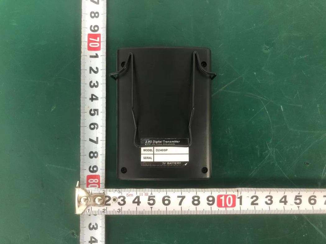
H38D2400P
Nov 26, 20252.4G Digital Transmitter
Equipment Class
DTS - Digital Transmission System
H38-RABT-ATS2819
May 09, 2023Bluetooth Module
Equipment Class
DTS - Digital Transmission System
H38WS-5
Oct 10, 2020PORTABLE SOUND SYSTEM WITH BLUETOOTH
Equipment Class
DSS - Part 15 Spread Spectrum Transmitter
H38WS-6
Sep 22, 2020PORTABLE SOUND SYSTEM WITH BLUETOOTH
Equipment Class
DSS - Part 15 Spread Spectrum Transmitter
H38WT-X
May 05, 2020PLL UHF Creative pen-shape microphone System
Equipment Class
DWM - Part 15 Wireless Microphone