H38WT-201WIRELESS MICROPHONE
SEIKAKU TECHNICAL GROUP LIMITED
Click to zoom
Application Details
- Equipment Class
- TBF - Licensed Broadcast Transmitter Held to Face
- Date of Grant
- May 20, 1999
- Application Purpose
- Original Equipment
- Date of Application
- Mar 03, 1999
- Equipment Note
- WIRELESS MICROPHONE
- Frequency Range
- 174.00000000 - 216.00000000
- Country
- Samoa
Documents & Files
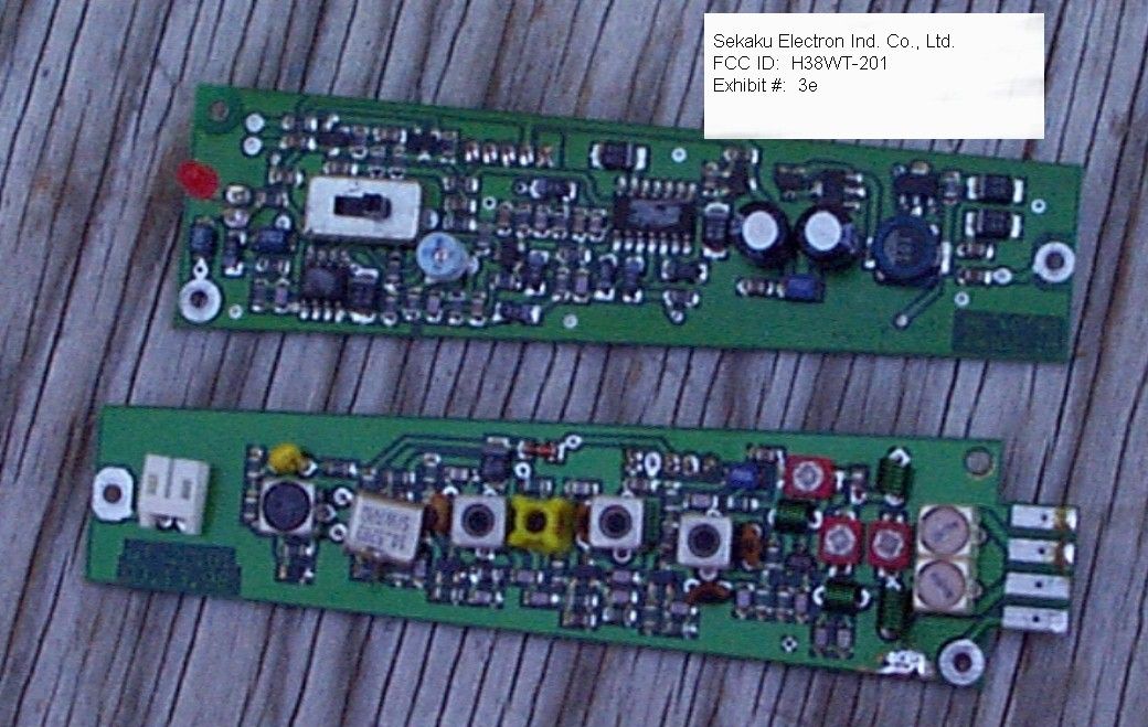
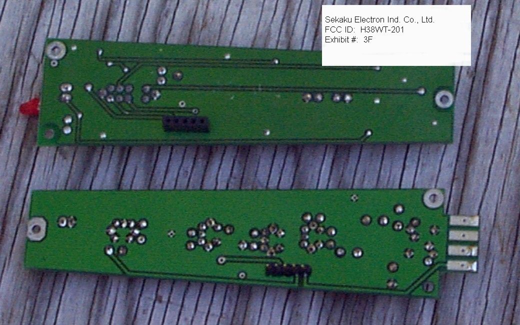
Document Text
Text extracted from the exhibit documents filed with the FCC. Open a document above to read the original.
Test Report
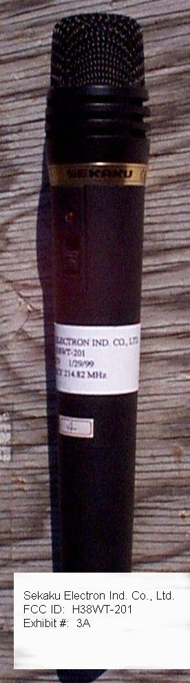
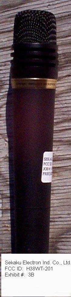
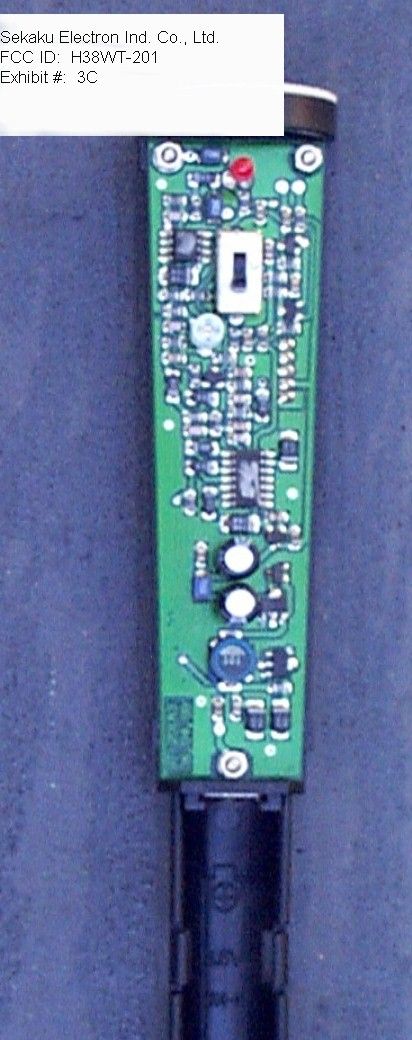
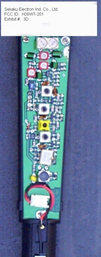
TABLE OF CONTENTS LIST APPLICANT: SEKAKU ELECTRON IND. CO., LTD. FCC ID: H38WT-201 TEST REPORT: PAGE 1......COVER SHEET - GENERAL INFORMATION & TECHNICAL DESCR. PAGE 2......TECHNICAL DESCRIPTION CONTINUED & RF POWER OUTPUT PAGE 3......RF POWER OUTPUT CONDT. & MODULATION CHARACTERISTICS PAGE 4......OCCUPIED BANDWIDTH PAGE 5......FIELD STRENGTH OF SPURIOUS EMISSIONS PAGE 6......METHOD OF MEASURING RADIATED SPURIOUS EMISSIONS PAGE 7......FREQUENCY STABILITY PAGE 8......CERTIFICATION OF TECHNICAL DATA AND LIST OF TEST EQUIPMENT EXHIBITS CONTANING: EXHIBIT 1.........POWER OF ATTORNEY LETTER EXHIBIT 2.........FCC ID LABEL SAMPLE AND SKETCH OF LOCATION EXHIBIT 3A........EXTERNAL FRONT VIEW PHOTOGRAPH EXHIBIT 3B........EXTERNAL REAR VIEW PHOTOGRAPH EXHIBIT 3C-3E.....INTERNAL COMPONENT SIDE PHOTOGRAPH EXHIBIT 3F........INTERNAL SOLDER SIDE PHOTOGRAPH EXHIBIT 4.........BLOCK DIAGRAM EXHIBIT 5A-5B.....SCHEMATICS EXHIBIT 6A-6G.....PARTS LIST EXHIBIT 7A-7E.....USER'S MANUAL EXHIBIT 8.........AUDIO FREQUENCY RESPONSE GRAPH EXHIBIT 9.........AUDIO INPUT VS DEVIATION GRAPH EXHIBIT 10........OCCUPIED BANDWIDTH PLOT - NO AUDIO EXHIBIT 11........OCCUPIED BANDWIDTH PLOT - 10 kHz TONE EXHIBIT 12........OCCUPIED BANDWIDTH PLOT - 15 kHz TONE EXHIBIT 13A-13B...CRYSTAL SPECIFICATIONS APPLICANT: SEKAKU ELECTRON IND. CO., LTD. FCC ID: H38WT-201 REPORT #: F:\CUS\S\SEK\SEK42T9.RPT PAGE: TABLE OF CONTENTS GENERAL_INFORMATION_REQUIRED FOR_TYPE_ACCEPTANCE 2.983 (a,b,c) SEKAKU ELECTRON IND. CO., LTD. will manufacture the H38WT-201 in quantity, for use under FCC RULES PART 74.801, LOW POWER AUXILIARY STATIONS. 2.983 (d) TECHNICAL_DESCRIPTION (1) Type of Emission: 160K0F3E Bn=2M+2DK M = 1000 D = 68.0KHz (Peak Deviation) K=1 Bn = 2(1K) + 2(68.0K)(1) = 2K +136.0K = 138.0KHz M = 15,000 D = 65KHz K=1 Bn = 2(15K) + 2(65K) = 30 +130 = 160KHz 74.861(e)(5) ALLOWED AUTHORIZED BANDWIDTH = 200KHz. (2) Frequency Range: Part 74: 161.625-161.775MHz & 174-216MHz TEST FREQ = 214.84MHz. (3) Power Range and Controls:UNIT has no power controls. (4) Maximum Output Power Rating: 1.0 MilliWatts ERP. (5) DC Voltages and Current into Final Amplifier: FINAL AMPLIFIER ONLY 1.5V BATTERY Vce = 3.4 Volts Ice = 8.0mA. (6) Function of each electron tube or semiconductor device or other active circuit device: IC1 LM358N AUDIO PREAMPLIFIER & LIMITER IC2 DS2101D Compressor TR1 STRS501 Buffer TR2 2SC241 Multiplier TR3 RB400D Multiplier TR4 XC6373A350PR Regulator TR5 XC6373A350PR POWER AMPLIFIER TR6 2SC2412K Regulator TR7 TR8 2SC2412K Buffer TR9 2SC2412K Tone Oscillator TR10 2SC2412K Buffer 2.983(d) (7) Complete Circuit Diagrams: The circuit diagram is included as EXHIBIT 5A-5B. The block diagram is included as EXHIBIT 4. The part list is included EXHIBIT 6A-6G. REPORT #: F:\CUS\S\SEK\SEK42T9.RPT PAGE: 1 2.983(d) (8) Instruction book. The instruction manual is in- cluded as EXHIBIT 7A-7E in this report. (9) Tune-up procedure. The tune-up procedure is given in page NA. (10) Description of all circuitry and devices provided for determining and stabilizing frequency. The transmitter frequency is controlled by a crystal, the crystal specifications are included in PAGE 13A-13B. (11) Description of any circuits or devices employed for suppression of spurious radiation, for limit- ing modulation, and for limiting power. There are no devices or circuitry to limit the power, since this is a low power device. The interstage cou- pling between TR1, TR2, TR3, TR4, and TR6 as well as the low pass filter made up of L2, VC1, C26, L3, VC2, C28, L4, L6, VC3, & C29 suppress the harmonics. Limiting Modulation: The transmitter audio circuitry is contained in IC2. The modulation limiting is also provided by IC1B. Limiting Power: There is no provision for limiting power. (12) Digital modulation. This unit does not use digital modulation. 2.983(e) The data required by 2.985 through 2.997 is sub- mitted below. 2.985(a) RF_power_output. ERP was measured by the method described later in this report. The input power to the final stage was measured with a 1.5V supply connected in place of the 1.5V battery. INPUT POWER: FOR 1.5 V OPERATION (3.4V)(0.008A) = 27.2milliWatts OUTPUT POWER: FOR 1.5 V OPERATION 1.0 mWATTS ERP APPLICANT: SEKAKU ELECTRON IND. CO., LTD. FCC ID: H38WT-201 REPORT #: F:\CUS\S\SEK\SEK42T9.RPT PAGE: 2 R.F. POWER OUTPUT /-------\ /-----------------\ | | | | TRANSMITTER | | | |HP | UNDER TEST WITH | \--| |SPECTRUM | INTERNAL ANTENNA| | | |ANALYZER \-----------------/ | | | | | \-------/ |?- 3.0 meters---?| /-------------\ | SIGNAL | DIPOLE | Tuned, Calibrated | GENERATOR | ANTENNA | Antenna which may | |----------/ be raised from 1 \-------------/ to 4 meters above ground and changed in polarization Equipment placed 1 meter above ground on a rotatable platform. The center of the Dipole antenna at the center of the platform and the output of the signal generator adjusted to produce the same meter reading as measured for the fundamental in the radiated emissions test. 2.987(a)(b) Modulation_characteristics: AUDIO_FREQUENCY_RESPONSE The audio frequency response was measured in accordance with TIA/EIA Specification 603 S2.2.6.2.1. with the follwoing excep- tions; Constant Deviation Test /---------------\ /----------\ /----------\ | Dummy | | Audio | | RMS | /-| Microphone |--| Generator| /-| VOLTMETER| | | | \----------/ | \----------/ | \---------------/ | |----------------------------------/ | /------------\ /------------\ /---------\ | | | | | | | | Test | | | Transmitter|---/ \----| NEAR FIELD|---| Receiver| \-| under test | | PROBE | | | \------------/ \------------/ \---------/ 1.The test receiver audio bandwidth was <50Hz to >20,000Hz. 2. Apply a 1000Hz tone and adjust the audio generator to produce 10% of the rated system deviation. 3. Measure frequency responce over the frequency range from 100Hz to 20,000Hz. The audio frequency response curve is shown in Exhibit 8. AUDIO_LOW_PASS_FILTER The audio low pass filter is not required in this unit. APPLICANT: SEKAKU ELE…
Text truncated - open the document above for the full version.
Contact Information
Applicant
Henry lee(R&D)
Technical Contact
Non-Technical Contact
TIMCO ENGINEERING, INC.SHARON A HOFFMAN
[email protected]8888-472-2424
Test Firm
Timco Engineering, Inc.Sid Sanders
Technical Specifications
| # | Rule Parts | Frequency Range | Power Output | Emission | Tolerance |
|---|---|---|---|---|---|
| 2 | 74.861 | 174 MHz - 216 MHz | 1.00 mW | 160KF3E | 0.005 % |
Other Applications from SEIKAKU TECHNICAL GROUP LIMITED
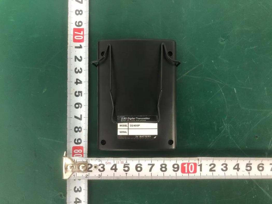
H38D2400P
Nov 26, 20252.4G Digital Transmitter
Equipment Class
DTS - Digital Transmission System
H38-RABT-ATS2819
May 09, 2023Bluetooth Module
Equipment Class
DTS - Digital Transmission System
H38WS-5
Oct 10, 2020PORTABLE SOUND SYSTEM WITH BLUETOOTH
Equipment Class
DSS - Part 15 Spread Spectrum Transmitter
H38WS-6
Sep 22, 2020PORTABLE SOUND SYSTEM WITH BLUETOOTH
Equipment Class
DSS - Part 15 Spread Spectrum Transmitter
H38WT-X
May 05, 2020PLL UHF Creative pen-shape microphone System
Equipment Class
DWM - Part 15 Wireless Microphone