H38X-100HHandheld Transmitter
SEIKAKU TECHNICAL GROUP LIMITED
Click to zoom
Application Details
- Equipment Class
- TNF - Licensed Non-Broadcast Transmitter Held to Face
- Date of Grant
- Apr 28, 2015
- Application Purpose
- Original Equipment
- Date of Application
- Apr 28, 2015
- Equipment Note
- Handheld Transmitter
- Frequency Range
- 174.00000000 - 216.00000000
- Country
- Samoa
Documents & Files
Document Text
Text extracted from the exhibit documents filed with the FCC. Open a document above to read the original.
Users Manual
IF YOU ARE NOT TECHNICALENGINEER PLS. DO NOTMODIFIED OR KNOCK - DOWNIT. NOTE WIRELESS SYSTEM INSTRUCTION MANUAL ON VOLUME1 VOLUME2 POWER ANTENNA Dual Receiver ANTENNA 1 Specifications : Character : Special circuit design to delete microphone switch ON/OFF noise.Compression / Expanded circuit for extended dynamic range.LED Indicator (Power,RF,AF) and telescopic antenna.Compact, lightweight,single channel receiver.from 160-245 MHzVHF High band frequency by quartz locked controlled. Range WeightDimensionsPower supplyOutput connectorAudio output levelReceiving modeFrequency responseS/N RatioDynamicT.H.D.Max. deviationModulation mode Frequency stability Carrier frequency range Receiving method With AC/DC adaptor 115/230V 50/60Hz 226g152 98 36 mm DC 12V ~ 18V 200mAUnbalance 6.3 mm phone jackAt deviation = 40KHzUnbalance ,300mV , 10K load W Quartz control fixed frequency50Hz-15KHz 3dB>90dB>100dB<1% 40KHz,,with limiting compress FM (F3E)0.005% /25 CVHF Hi-Band 160-245MHzNon-diversity receiver 2 5. Power Input Connect4. Audio Output Connector3. Telescopic Antenna2. VR And Therefore / Volume Control1. Power ON Indicator NAMES OF PARTS FREQ. SERIAL 1. 4. 5. 2. 3. 3 4 4. Power switch & volume control: off adjust the volume control to be switched on and the volume Adjust the volume control to"OFF" state, the unit will be powered "ON" direction, the power willcan also be contrtolled. VOLUME1 VOLUME2 POWER ANTENNA Dual Recei FIG.4 a. Power ON Indicator: This red light glows when the DC supply and power SwitchON. It indicates that the rece-iver is on. b. Reception Indicator: This indicator does light during standby. When microphonesignal is received, The Blue indicatorlight to indicate the reception of microphone. MANUEL D'INSTRUCTION 1. Install AntennaReceivers signals from the transmitter.Make sure the antenna is fullyextended vertically. INSTRUCTION MANUAL 2.Audio Output ConnectorYou can connect an unbalancedaudio cable with a 1/4 inch phoneplug between this connector andyour mixer or amplifier input. FIG.1 UNBAL IN FIG.2 MIC / AUX INPUT FIG.3 12V-15V DC IN 3. Power Supply Connection Use DC power supplycould switch with adaptorsupply or batter of12-18V DC.ConnectionDC supply ,DC plugconn-ection with "DC-IN"socket. (See FIG.3) anotherplug terminal connection withbattery or power supply. FREQ. SERIAL 5 4.Battery information Note: Make sure the power switch is in the"OFF'position. When changing or installing new battery. For efficient use please install a new 9V alkali battery before use standby ON 6 ON 1.Feature: Quality capsule head make your sound performance more perfect 2.Specification:hand-hold (1).Quartz locked control Modulation modeCarrier frequency rangeFrequency stabilityMAX. deviationPre-emphasisTHDRF powerFrequency rangeDynamic rangeBatteryCurrent consumptionBattery lifeDimensionsWork temperature FM(F3E)160-245MHz 0.005% 2540KHz 50 S 45dBc10mW50Hz-15KHz100dB9V30mA6-8hr.240cm-10 ~+60 3.Parts name: 1/Grille holder2/Power LED3/Tube4/Color ring5/Neck ring6/Switch7/Switch cover8/Tail tube 12 3 4 5 67 8 1 2 7 8 3 5 SENS 123 1. SOCKET2. VOLUME CONTROL3. POWER SWITCH4. LED INDICATOR 5. BATTERY COVER6.7.8. MIC SENSITIVITY SWITCHINGLABEBELT CLIP 4 6 FEATURE:SMALL POCKBODY TYPE LIKE A POCKET SIZE.IT IS VERY EASY CARRYING, ANTENNA BUILT-INSIDE.OTHER FEATURES: 7. LABE 1. SOCKET 3.5 JACK 4P mini XLR PLUG 2. VOLUME CONTROL LargeSmall 3. POWER SWITCH ONSTAND BYOFF 4. LED INDICATOR BATTER LOWCHANGING BATTER WHEN LIGHT-ON 6. MIC SENSITIVITY SWITCHING FOR ELECTRICAL INSTRUMENTFOR DYNAMIC MICROPHONEFOR CONDENSER MICROPHONE 8. BELT CLIP 2 WAYS FOR HANGING VERTICALCROSSWISE 5. BATTERY COVER 1. AFTER OPERATION THE MICROPHONE MUST BE SWITCHED OFF AS WELL. OTHERWISE THE BATTERIES WILL SOON BE EXHAUSTED.IN ORDER TO AVOID UNTUNEFUL CON- SUPMPTION OF THE INNER BATTERY: IF PILOT LAMP OF THE WIRELESS MICROPHONE (1)REMAINS LIGHTED, IT MEANS THAT THE BATTERY HAS NO MORE POWER: (2) THE LAMP MUST FLASH ONLY FOR THE TIME OF THE SWITCHING -ON; THIS INDICATES THAT THE MICROPHONE WORKS WELL. INSTRUCTION 2. INSTALL BATTERY: PLS. MAKE SURE THE POSITIVE/NE- GATIVE BEFORE YOU REPLACEMENT BATTERIES. SPECIFICATIONS FM(F3E)160MHz~245MHzQuartz controlled fixed frequency Modulation modeFrequency bandReceiving modeRF output powerCurrent drainBattery life (alkali)BatteryTone frequencyFrequency responseFrequency stabilityRated deviationSpurious emissionsDimensionsNet weight 45dBc106(L) 23(W) 66(H)mm (4.2L 0.9W 2.6H in80g (0.177 bs)15mW<30mAMore than 7~8 hours9V Alkaline Battery32.768KHz50Hz~15KHz 0.005%/2540KHz(MAX) 7 8 WE CONGRATULATE YOU FOR THECHOICE OF THIS EXCELLENT PROFE-SSIONAL APPARATUS MICROPHONEWHICH WILL GIVE YOU OUTSTANDINGRESULTS AT THE HIGH FIDELITY.THE MICROPHONE SUIT FOR SCHOOLSPEECH, MEETING SPEECH, TEACHERSAND PERFORMER ON THE STAGE.TO AVOID OF PROBLEM LIKE WIREMICROPHONE.THE BODY PACK MICROPHONE CONNE-CTION IN EVERY WORKING CONDITION. 1. BATTERY USE DC9V2. DO NOT DROP THE MICROPHONE BODY ON THE FLOOR. 3. PROTECT THE UNITS AGAINST HUMIDITY AND HEAT. 4. IF THE UNITS ARE TO BE PUT OUT OF OPERATION DEFINITIVELY,BRING THEM TO TECHNICALENGINEER FOR DISPOSAL. INTRODUCTION CAUTION LS-16/4B LM-10/4B HM-26/4B DIAGRAM: 9
ID Label/Location Info
Label & Location
Test Report
TÜV Rheinland LGA Products GmbH Tillystrasse 2 D-90431 Nürnberg Tel.: +49 911 655 5225 Fax +49 911 655 5226 Mail: [email protected] Web: www.tuv.com Produkte Products Prüfbericht-Nr.: Test Report No.: 16056492 001 Auftrags-Nr.: Order No.: 174013631 Seite 1 von 34 Page 1 of 34 Kunden-Referenz-Nr.: Client Reference No.: 352690 Auftragsdatum: Order date.: 20.May 2014 Auftraggeber: Client: Seikaku Technical Group Limited Offshore Chambers, P.O. Box 217 Apia, Samoa. Prüfgegenstand: Test item: Handheld Transmitter Bezeichnung / Typ-Nr.: Identification / Type No.: X-100H, X-200H FCC ID: H38X-100H FCC ID: Auftrags-Inhalt: Order content: TUV Rheinland - EMC service Prüfgrundlage: Test specification: TIA/EIA-603-C-2004 FCC 47 CFR Part 74.861, Subpart H: 2013 Wareneingangsdatum: Date of receipt: 28.May 2014 Prüfmuster-Nr.: Test sample No.: 174013631-001 Prüfzeitraum: Testing period: Refer to test report Ort der Prüfung: Place of testing: TÜV Rheinland (Guangdong) Ltd. Prüflaboratorium: Testing laboratory: TÜV Rheinland (Guangdong) Ltd. EMC Laboratory Prüfergebnis*: Test result*: Pass geprüft von / tested by: Frank Du 21.Oct.2014 Project Manager kontrolliert von / reviewed by: Liangdong Xie 21.Oct.2014 Project Manager Datum Date Name/Stellung Name/Position Unterschrift Signature Datum Date Name/Stellung Name/Position Unterschrift Signature Sonstiges / Other: Zustand des Prüfgegenstandes bei Anlieferung: Condition of the test item at delivery: Prüfmuster vollständig und unbeschädigt Test item complete and undamaged * Legende: 1 = sehr gut 2 = gut 3 = befriedigend 4 = ausreichend 5 = mangelhalt P(ass) = entspricht o.g. Prüfgrundlage(n) F(ail) = entspricht nicht o.g. Prüfgrundlage(n) N/A = nicht anwendbar N/T = nicht getestet Legend: 1 = very good 2 = good 3 = satisfactory 4 = sufficient 5 = poor P(ass) = passed a.m. test specifications(s) F(ail) = failed a.m. test specifications(s) N/A = not applicable N/T = not tested Dieser Prüfbericht bezieht sich nur auf das o.g. Prüfmuster und darf ohne Genehmigung der Prüfstelle nicht auszugsweise vervielfältigt werden. Dieser Bericht berechtigt nicht zur Verwendung eines Prüfzeichens. This test report only relates to the a. m. test sample. Without permission of the test center this test report is not permitted to be V04 duplicated in extracts. This test report does not entitle to carry any test mark. Produkte Products Prüfbericht - Nr.: Test Report No. 16056492 001 Seite 2 von 35 Page 2 of 35 TEST SUMMARY 5.1 RADIATED POWER OUTPUT MEASUREMENT RESULT: Pass 5.2 SPURIOUS RADIATION MEASUREMENT (TX) RESULT: Pass 5.3 MODULATION CHARACTERISTICS MEASUREMENT RESULT: Pass 5.4 OCCUPIED BANDWIDTH RESULT: Pass 5.5 FREQUENCY TOLERANCE RESULT: Pass 5.6 EMISSION MASK RESULT: Pass 5.7 ELECTROMAGNETIC FIELDS RESULT: Pass Produkte Products Prüfbericht - Nr.: Test Report No. 16056492 001 Seite 3 von 35 Page 3 of 35 Contents 1 GENERAL REMARKS ............................................................................................................ 5 1.1 COMPLEMENTARY MATERIALS .......................................................................................... 5 2 TEST SITES .......................................................................................................................... 5 2.1 TEST FACILITIES ................................................................................................................. 5 2.2 LIST OF TEST AND MEASUREMENT INSTRUMENTS ............................................................. 5 2.3 TRACE ABILITY.................................................................................................................... 6 2.4 CALIBRATION ...................................................................................................................... 6 2.5 ABBREVIATIONS .................................................................................................................. 6 2.6 MEASUREMENT UNCERTAINTY ........................................................................................... 6 3 GENERAL PRODUCT INFORMATION .................................................................................... 7 3.1 PRODUCT FUNCTION AND INTENDED USE........................................................................... 7 3.2 RATING AND PHYSICAL CHARACTERISTICS ....................................................................... 7 3.3 NOISE GENERATING OR SOURCES OF INTERFERENCE ....................................................... 8 3.4 NOISE SUPPRESSING PARTS ................................................................................................ 8 3.5 SUBMITTED DOCUMENTS .................................................................................................... 8 4 TEST SET-UP AND OPERATION MODES ............................................................................... 9 4.1 TEST METHODOLOGY ......................................................................................................... 9 4.2 INDEPENDENT AND TEST OPERATION MODES .................................................................... 9 4.3 SPECIAL ACCESSORIES AND AUXILIARY EQUIPMENT ........................................................ 9 4.4 COUNTERMEASURES TO ACHIEVE EMC COMPLIANCE ...................................................... 9 4.5 TEST SETUP ....................................................................................................................... 10 5 TEST RESULTS E M I S S I O N ...................................................................................... 11 5.1 CONDUCTED POWER OUTPUT MEASUREMENT .................................................................. 11 5.2 SPURIOUS RADIATION MEASUREMENT ............................................................................ 14 5.3 MODULATION CHARACTERISTICS MEASUREMENT .......................................................... 27 5.4 OCCUPIED BANDWIDTH ...........................................................…
Text truncated - open the document above for the full version.
Test Report
Produkte Products Prüfbericht - Nr.: Test Report No. 16056492 001 Seite 31 von 34 Page 31 of 34 5.7 Electromagnetic Fields RESULT: PASS Date of testing : 17 Oct 2014 Guide : FCC KDB Publication 447498 The minimum distance for the EUT is <5mm, since maximum peak output power of the transmitter is 20.6mW (13.12dBm) < 27mW, hence the EUTs are excluded from SAR evaluation according to FCC KDB publication 447498 D01: Mobile and Portable RF Exposure. Guidance v05.
Contact Information
Applicant
Henry lee(R&D)
Technical Contact
Dongguan Jingheng Electron Co., Ltd.Alex Xie
[email protected]8676988977068
Shenshan Industrial City, Hengli Town · Dongguan, Guangdong · China
Test Firm
TUV Rheinland (GuangDong) Ltd.Yuxin Huang
Technical Specifications
| # | Rule Parts | Frequency Range | Power Output | Emission | Tolerance |
|---|---|---|---|---|---|
| 1 | 74 | 174 MHz - 216 MHz | 20.60 mW | 90K2F3E | 3320.0000000000 Hz |
Other Applications from SEIKAKU TECHNICAL GROUP LIMITED
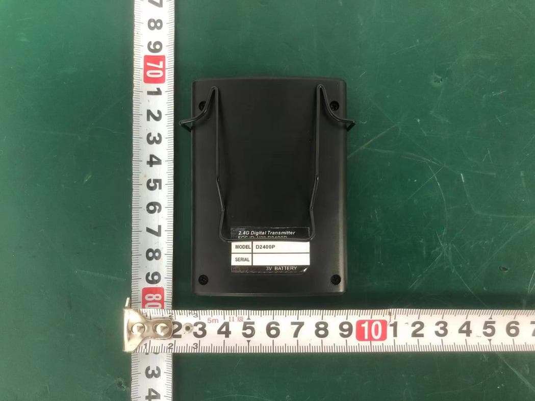
H38D2400P
Nov 26, 20252.4G Digital Transmitter
Equipment Class
DTS - Digital Transmission System
H38-RABT-ATS2819
May 09, 2023Bluetooth Module
Equipment Class
DTS - Digital Transmission System
H38WS-5
Oct 10, 2020PORTABLE SOUND SYSTEM WITH BLUETOOTH
Equipment Class
DSS - Part 15 Spread Spectrum Transmitter
H38WS-6
Sep 22, 2020PORTABLE SOUND SYSTEM WITH BLUETOOTH
Equipment Class
DSS - Part 15 Spread Spectrum Transmitter
H38WT-X
May 05, 2020PLL UHF Creative pen-shape microphone System
Equipment Class
DWM - Part 15 Wireless Microphone